Thingiverse
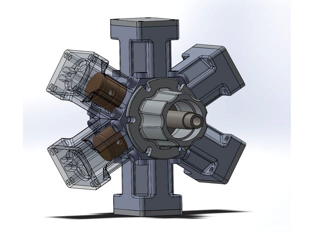
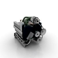
6 cylinder radial 'steam' engine by Xaxis
by Thingiverse
Last crawled date: 3 years ago
This is very much a work in progress, updates often! I would appreciate comments on how to present this project as well as thoughts on improving the prints/part designs.
EDIT: WARNING DO NOT ACTUALLY TRY TO RUN THIS WITH HOT STEAM!!!
Do I have to say this? I feel like I have to say this... sheeesh people! Ok, it has been said, DO NOT TRY THIS WITH ACTUAL STEAM!
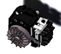
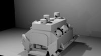
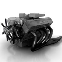
A radial steam engine commonly seen as a 3 cylinder version, often used as a machining learning and hobbyist model making project. Reworked into a 6 cylinder radial engine. Now a 3d printing and additive manufacturing learning and model making project!
2 Cylinder types, simple printed inner diameter which can be sanded and used with o-rings, and one with space for piston sleeves and o-rings for a more realistic function.
Better instructions on assembly coming soon! Short exploded view video shows part order of assembly. But you might be able to figure it out just from the parts, and if you like a puzzle... well there you go!
Note: You may also print only 3 cylinders and pistons, 2 slave rods and one master rod, and make the model as a 3 cylinder. Cover the other 3 openings with the 'cylinder head basic' part or look through at the inside, which is sort of neat. Plugging the ports for those cylinders would allow compression (if you can print well enough on your machine it seals, i will need gaskets of something using my i3).
Assembly video here:https://www.youtube.com/watch?v=Hq6cbk3r5GQ&feature=youtu.be
This miniature model steam engine uses some non-printed parts for better function:
EDIT: NOT ACTUALLY SKATEBOARD BEARINGS!!! 2x skateboard bearings (608Z 8x22x7mm bearings) on the crankshaft
-THIS IS WRONG BEARING SORRY!!!
This is a 1604zz bearing from what I have googled.
The shaft is 9.45mm and needs a bearing with an inner diameter of 9.5mm or .375inch.
The outer diameter to fit the bearing housing is 22.2mm or .875inch.
The width is 7.1mm or .28inch.
I specifically used EZO R6RS bearings, which might be expensive being HQ Japanese manufactured bearings. Cheaper of the same size will work fine.
1/4" x 1" tube or rod as the offset portion of the crankshaft. Piston rods attach to this.
1/8" tube or rod, used as piston pins pressed in connecting the piston rods. use heat to press in. Works good.
1/8" tube or rod, connecting the piston slave rods to the piston master rod... still have to work out how to retain these pins better... for now i'm actually using screws and nuts but it seems very inelegant. So brass rod and I will make models of little press fit end caps for it, better than screws.
EDIT: 1/8" tube not functional for Slave/Master Rod mounting! Use 5 M4 10mm set screws to attach the Slave Rods to the Master Rod. Slave Rods will thread lightly with no tapping, master will act as stop nut with half tapping (stopping before full tap diameter), rotation on the threads by slave rods is smooth and does not translate to enough movement to bind the pistons. So this is how it will be done in lieu of a better solution (which you are welcome to remix yourself) .
6x 6mm M3 screws to attach the main bearing housing.
6x 15mm M3 screws to attach the Steam Chest and Steam Chest Cover.
24x 35mm M3 screws to attach the Cylinders and Cylinder Head Covers.
36 x M3 brass knurl nuts, heat inserted with a soldering iron into the crank case. Guides are available through google 'brass insert 3d printing'.
Edit 8/12/2016:
I will upload a no insert version of the Crank Case with 2.5mm holes for hand tapping, for those that do not want to use so many inserts and would like to simply thread and screw the parts together. Note that the threads in plastic will wear out if the engine is disassembled and reassembled enough.
So I am posting the models and some pics but I intend to remodel the cylinders to fit a common thin walled .5" ID tubing that will serve as piston liners, aluminum or acrylic are types I will explore. This is so the piston can have o-rings ride on a very smooth surface and achieve good compression.
The main motivation for making and uploading this is for teachers to demonstrate engineering to young students, so it's a learning model I suppose. It uses a timing system based on opening and closing ports aligned to radial geometry rather than push rods and separate moving valves for each cylinder. So it is somewhat easier to make in my opinion and is more creatively minimalist in how it approaches mechanical design.
I am putting together some instructions on how to assemble, as well as an explanation of features in this design that were changed for additive manufacturing versus subtractive machining. Hopefully some teachers can make lesson plans for a fun 3d printing project that teaches basics of compressors/engines and basic mechanical design.
I am posting it a bit earlier than I wanted because I am switching from Solidworks to Fusion 360 for CAD and I am not sure when I will get back to it, so I am doing the revisions I can before my academic license for Solidworks runs out. After that there will be some learning curve to overcome before I can get back to it.
Again, it is a work in progress. However it shouldn't be to long before the modeling and designing process is finalized.
----UPDATES BELOW----
UPDATE 8/18/2016: Added crank spacer parts, 4mm and 5mm. These can be used to help center the piston arms on the crank rod.
UPDATE 8/12/2016:
Changed Orbital_Valve part to improved part, side cut allows better airflow in 12 c'clock position when valve is closest to inlet/outlet port on steam chest.
Changed Rod_Master file to new version with integrated spacer on the return crank side.
Changed Crankshaft file to improved version with holes for mounting Rod_Slave parts to Rod_Master with the crankshaft installed in the crank case.
Changed Piston part to narrower pin insert holes for 3.18mm brass tube (1.8") and deeper O ring channels.
Test unit functions well, Rod_Slave file needs adjustment for a slight clearance issue. Earlier part is fixable with chamfer applied (cut or sanded) to the outer vertical edges of the 2 prong extensions that fit around the Rod_master crank shaft mounting disk. Those edges scrape on the copper inserts but clearance needed is only around .5mm so a minor cut or sanding will fix this on parts already printed, and only applies to the copper inserts.
UPDATE 8/9/2016: New cylinder model added, labeled R3-6C_CylinderSleeved_3DPV3_Print1, left old cylinder model labeled R3-6C_Cylinder_3DPV2_Print1 in downloads, use old V2 for no copper sleeves. The better your printer the smoother it will be. Use the new model if you want sleeves, which are intended to help o-rings seal and run low pressure air so the model functions as the design is intended. This will also need gaskets made for all the contact surfaces that can leak air, or very precise sanding without loosing to much height on any surface.
Also switched UPDATE list to below main text for clarity.
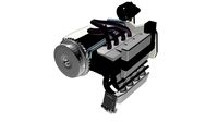
UPDATE 8/8/2016: Piston Sleeves! As the new images show, a 1/2 ID copper pipe section will be used for the piston sleeves. It is .628" (16mm) actual inner diameter measured with calipers, .702" (17.85mm) outer diameter, and1" (28mm) long. This should be standard copper pipe straight joint available at the hardware store, as that is where I got it. You will need 6 of course. This will give the O-rings a nice smooth surface to slide on, especially if buffed with a dremel polisher and some polishing compound. This should get the engine closer to operating as a model steam engine on compressed air. I will be posting a new STL file of a redesigned Cylinder and Cylinder head that work with this new metal part.
I will be sourcing the right o-ring, post the part info, and move on to finalizing this with some instructions on the engines assembly, possible function beyond manually turning the drive shaft (low pressure compressed air, which is untested yet), and a little bit about the original designer if I can find it. As I recall it was some guy from Victorian era Great Britain that drew up the first 3 cylinder radial with orbital valve like this, will research it more...
Final models within 10 days as that is all I have left on my Solidworks license before switching to Fusion 360.
Also here is a link to the engine's origin, it was along time ago in a galaxy far far away... http://www.homemodelenginemachinist.com/showthread.php?t=11127
UPDATED 8/4/2016 2pm PST:
New Piston model. Square profile O-ring seat with .4mm 45 degree chamfer for printing the overhang.
EDIT: WARNING DO NOT ACTUALLY TRY TO RUN THIS WITH HOT STEAM!!!
Do I have to say this? I feel like I have to say this... sheeesh people! Ok, it has been said, DO NOT TRY THIS WITH ACTUAL STEAM!
A radial steam engine commonly seen as a 3 cylinder version, often used as a machining learning and hobbyist model making project. Reworked into a 6 cylinder radial engine. Now a 3d printing and additive manufacturing learning and model making project!
2 Cylinder types, simple printed inner diameter which can be sanded and used with o-rings, and one with space for piston sleeves and o-rings for a more realistic function.
Better instructions on assembly coming soon! Short exploded view video shows part order of assembly. But you might be able to figure it out just from the parts, and if you like a puzzle... well there you go!
Note: You may also print only 3 cylinders and pistons, 2 slave rods and one master rod, and make the model as a 3 cylinder. Cover the other 3 openings with the 'cylinder head basic' part or look through at the inside, which is sort of neat. Plugging the ports for those cylinders would allow compression (if you can print well enough on your machine it seals, i will need gaskets of something using my i3).
Assembly video here:https://www.youtube.com/watch?v=Hq6cbk3r5GQ&feature=youtu.be
This miniature model steam engine uses some non-printed parts for better function:
EDIT: NOT ACTUALLY SKATEBOARD BEARINGS!!! 2x skateboard bearings (608Z 8x22x7mm bearings) on the crankshaft
-THIS IS WRONG BEARING SORRY!!!
This is a 1604zz bearing from what I have googled.
The shaft is 9.45mm and needs a bearing with an inner diameter of 9.5mm or .375inch.
The outer diameter to fit the bearing housing is 22.2mm or .875inch.
The width is 7.1mm or .28inch.
I specifically used EZO R6RS bearings, which might be expensive being HQ Japanese manufactured bearings. Cheaper of the same size will work fine.
1/4" x 1" tube or rod as the offset portion of the crankshaft. Piston rods attach to this.
1/8" tube or rod, used as piston pins pressed in connecting the piston rods. use heat to press in. Works good.
1/8" tube or rod, connecting the piston slave rods to the piston master rod... still have to work out how to retain these pins better... for now i'm actually using screws and nuts but it seems very inelegant. So brass rod and I will make models of little press fit end caps for it, better than screws.
EDIT: 1/8" tube not functional for Slave/Master Rod mounting! Use 5 M4 10mm set screws to attach the Slave Rods to the Master Rod. Slave Rods will thread lightly with no tapping, master will act as stop nut with half tapping (stopping before full tap diameter), rotation on the threads by slave rods is smooth and does not translate to enough movement to bind the pistons. So this is how it will be done in lieu of a better solution (which you are welcome to remix yourself) .
6x 6mm M3 screws to attach the main bearing housing.
6x 15mm M3 screws to attach the Steam Chest and Steam Chest Cover.
24x 35mm M3 screws to attach the Cylinders and Cylinder Head Covers.
36 x M3 brass knurl nuts, heat inserted with a soldering iron into the crank case. Guides are available through google 'brass insert 3d printing'.
Edit 8/12/2016:
I will upload a no insert version of the Crank Case with 2.5mm holes for hand tapping, for those that do not want to use so many inserts and would like to simply thread and screw the parts together. Note that the threads in plastic will wear out if the engine is disassembled and reassembled enough.
So I am posting the models and some pics but I intend to remodel the cylinders to fit a common thin walled .5" ID tubing that will serve as piston liners, aluminum or acrylic are types I will explore. This is so the piston can have o-rings ride on a very smooth surface and achieve good compression.
The main motivation for making and uploading this is for teachers to demonstrate engineering to young students, so it's a learning model I suppose. It uses a timing system based on opening and closing ports aligned to radial geometry rather than push rods and separate moving valves for each cylinder. So it is somewhat easier to make in my opinion and is more creatively minimalist in how it approaches mechanical design.
I am putting together some instructions on how to assemble, as well as an explanation of features in this design that were changed for additive manufacturing versus subtractive machining. Hopefully some teachers can make lesson plans for a fun 3d printing project that teaches basics of compressors/engines and basic mechanical design.
I am posting it a bit earlier than I wanted because I am switching from Solidworks to Fusion 360 for CAD and I am not sure when I will get back to it, so I am doing the revisions I can before my academic license for Solidworks runs out. After that there will be some learning curve to overcome before I can get back to it.
Again, it is a work in progress. However it shouldn't be to long before the modeling and designing process is finalized.
----UPDATES BELOW----
UPDATE 8/18/2016: Added crank spacer parts, 4mm and 5mm. These can be used to help center the piston arms on the crank rod.
UPDATE 8/12/2016:
Changed Orbital_Valve part to improved part, side cut allows better airflow in 12 c'clock position when valve is closest to inlet/outlet port on steam chest.
Changed Rod_Master file to new version with integrated spacer on the return crank side.
Changed Crankshaft file to improved version with holes for mounting Rod_Slave parts to Rod_Master with the crankshaft installed in the crank case.
Changed Piston part to narrower pin insert holes for 3.18mm brass tube (1.8") and deeper O ring channels.
Test unit functions well, Rod_Slave file needs adjustment for a slight clearance issue. Earlier part is fixable with chamfer applied (cut or sanded) to the outer vertical edges of the 2 prong extensions that fit around the Rod_master crank shaft mounting disk. Those edges scrape on the copper inserts but clearance needed is only around .5mm so a minor cut or sanding will fix this on parts already printed, and only applies to the copper inserts.
UPDATE 8/9/2016: New cylinder model added, labeled R3-6C_CylinderSleeved_3DPV3_Print1, left old cylinder model labeled R3-6C_Cylinder_3DPV2_Print1 in downloads, use old V2 for no copper sleeves. The better your printer the smoother it will be. Use the new model if you want sleeves, which are intended to help o-rings seal and run low pressure air so the model functions as the design is intended. This will also need gaskets made for all the contact surfaces that can leak air, or very precise sanding without loosing to much height on any surface.
Also switched UPDATE list to below main text for clarity.
UPDATE 8/8/2016: Piston Sleeves! As the new images show, a 1/2 ID copper pipe section will be used for the piston sleeves. It is .628" (16mm) actual inner diameter measured with calipers, .702" (17.85mm) outer diameter, and1" (28mm) long. This should be standard copper pipe straight joint available at the hardware store, as that is where I got it. You will need 6 of course. This will give the O-rings a nice smooth surface to slide on, especially if buffed with a dremel polisher and some polishing compound. This should get the engine closer to operating as a model steam engine on compressed air. I will be posting a new STL file of a redesigned Cylinder and Cylinder head that work with this new metal part.
I will be sourcing the right o-ring, post the part info, and move on to finalizing this with some instructions on the engines assembly, possible function beyond manually turning the drive shaft (low pressure compressed air, which is untested yet), and a little bit about the original designer if I can find it. As I recall it was some guy from Victorian era Great Britain that drew up the first 3 cylinder radial with orbital valve like this, will research it more...
Final models within 10 days as that is all I have left on my Solidworks license before switching to Fusion 360.
Also here is a link to the engine's origin, it was along time ago in a galaxy far far away... http://www.homemodelenginemachinist.com/showthread.php?t=11127
UPDATED 8/4/2016 2pm PST:
New Piston model. Square profile O-ring seat with .4mm 45 degree chamfer for printing the overhang.
Similar models
grabcad
free

Radial Engine
...piston. the bearing 4 is used at the big end of
the master rod; the end of which is connected to the crank pin of the crankshaft.
thingiverse
free

Smaller piston which fits into a copper 3/8" coupling. by BrooklynBay
...erting them cold will be difficult without light sanding, and will cause the rods to crack over time if they are made out of pla.
grabcad
free

Radial Engine
...1.piston
2.piston ring
3.crank
4.connecting rod
5.master rod
6.link arm
7.piston pin plug
8.upper bush
9.lower bush
10.piston pin
grabcad
free

Radial engine piston assembly
...radial engine piston assembly
grabcad
piston and crank assembly of the radial engine with five cylinders
grabcad
free

6 Cylinder Radial Engine Stress Analysis
...ess analysis of cylinder, piston, piston ring, crankshaft, crankshaft valve crank, crankshaft counterweight, crankshaft pin parts
grabcad
free

Cylinder Engine
...ot;cylinder engine" consists of 4 cylinders,
i used only the cranckshaft, piston rings, piston pins and the connecting rods.
grabcad
free

piston, connecting rod and assembly
...ir assembly in which having piston connecting rod ,rod bush,piston pin,piston ring,master rod ,master rod bearing,articulated rod
grabcad
free

Steam Engine Crosshead
...ng rod like on trunk engines. therefore, the longitudinal dimension of the crosshead must be matched to the stroke of the engine.
grabcad
free

Radial Engine
...re are pistons, connecting rods, crankshaft, cylinder liners, piston bolts, piston plugs and piston rings included in the model.
grabcad
free

Vertical Steam Engine
...otational force for work. in case of this steam engine, engine has the crank shaft vertically above or below a vertical cylinder.
Xaxis
thingiverse
free

Tilt Xaxis by natko
...tilt xaxis by natko
thingiverse
xaxis parts for tilt printer, will fit on a cupcake with abp
thingiverse
free

Artillery Sidewinder-X1 Xaxis covers
...artillery sidewinder-x1 xaxis covers
thingiverse
a quick remix, added m5 holes.
thingiverse
free

Kingroon KP3S Xaxis Endstop parts by ReiyaSalt
...kingroon kp3s xaxis endstop parts by reiyasalt
thingiverse
nozzle: 0.4mm
thingiverse
free

Hictop xaxis clamp by Gen0idea
...oken x-axis belt clamp on the hictop printer.
printed in a different colour to the original to differentiate it as a replacement.
thingiverse
free

Hictop xaxis clamp by Gen0idea
...oken x-axis belt clamp on the hictop printer.
printed in a different colour to the original to differentiate it as a replacement.
thingiverse
free

CNC Xaxis carriage tension adjust
...nsion adjust
thingiverse
this is the x carriage tension adjuster for the cnc2-axis-4030b.
i used a spring to adjust the tension.
thingiverse
free

TopsCNC Nema 23 XAxis ZAxis Motor_Holder by kamibal
...topscnc nema 23 xaxis zaxis motor_holder by kamibal
thingiverse
z achse x achse motor halterung für nema 23
thingiverse
free

Twisted Heart Vase 1 by Xaxis
...setting on vase mode with perimeter at 50%). taulman in-pla, which is awesome but i heard it was discontinued :( bring it back!
thingiverse
free

Robo 3D R1 Xaxis cable support by Dazzer
...is cable out of the way. i put a couple of tie wraps on each side of the cable to stop it sliding around, seems to work a treat!!
thingiverse
free

Xaxis bowden extruder holder by ajna8093
...sing 3dbest purple pla. i recommend petg or something more durable as the stepper gets hot. so far mine has yet to warp or break.
Radial
3d_ocean
$5

Radial engine
...dial engine
3docean
engine radial
this is a radial engine used by the old airplanes. it is made in autodesk inventor and autocad.
3d_export
$5
radial engine
...ne , clearly shows how a radial engine works and all the parts present in it for a student or an engineer to have a glans on it .
3d_export
$5

shaft radial bearing
...shaft radial bearing
3dexport
shaft radial bearing
turbosquid
$7

Radial engine
...bosquid
royalty free 3d model radial engine for download as on turbosquid: 3d models for games, architecture, videos. (1672376)
turbosquid
$7

Radial Tyre
...osquid
royalty free 3d model radial tyre for download as max on turbosquid: 3d models for games, architecture, videos. (1433150)
turbosquid
$60

Radial engine
... available on turbo squid, the world's leading provider of digital 3d models for visualization, films, television, and games.
turbosquid
$35

VOITH RADIAL PROPELLER
...alty free 3d model voith radial propeller for download as max on turbosquid: 3d models for games, architecture, videos. (1338129)
3d_export
$20

radial engine assembly
...radial engine assembly
3dexport
turbosquid
$4
Radial Hair Brush
... 3d model radial hair brush for download as max, obj, and fbx on turbosquid: 3d models for games, architecture, videos. (1183870)
turbosquid
$39

Wheel ATS Radial
... available on turbo squid, the world's leading provider of digital 3d models for visualization, films, television, and games.
Steam
3d_export
$28

steam locomotive
...steam locomotive
3dexport
## steam locomotive
turbosquid
$1

Steam
...m
turbosquid
royalty free 3d model steam for download as obj on turbosquid: 3d models for games, architecture, videos. (1626376)
3d_ocean
$15

Steam iron
...ign made by me. you can use it for your projects and games as you want. iron, steam iron, philips,siemens, clothes,ironing, tefal
3d_export
$5

steam locomotive
...steam locomotive
3dexport
road. low-poly model steam train
3d_export
$10

bitron steam press
...bitron steam press
3dexport
bitron steam press
3d_export
$5

sauna steam room
...sauna steam room
3dexport
sauna steam room
3d_export
$10

steamed buns
...steamed buns
3dexport
3d_export
$7

steam locomotive
...steam locomotive
3dexport
turbosquid
$100

Steam Train
...osquid
royalty free 3d model steam train for download as fbx on turbosquid: 3d models for games, architecture, videos. (1166089)
turbosquid
$49

Steam machine
...quid
royalty free 3d model steam machine for download as fbx on turbosquid: 3d models for games, architecture, videos. (1486836)
Cylinder
turbosquid
$1

Piston - Cylinder Cylinder Engine
...nder cylinder engine for download as ige, obj, stl, and sldpr on turbosquid: 3d models for games, architecture, videos. (1235278)
3ddd
$1

sofa cylinder
...sofa cylinder
3ddd
круглый
sofa cylinder
turbosquid
$1

Cylinder Head - Single Cylinder Engine
...ngle cylinder engine for download as ige, obj, stl, and sldpr on turbosquid: 3d models for games, architecture, videos. (1222618)
turbosquid
$16

Cylinder
... available on turbo squid, the world's leading provider of digital 3d models for visualization, films, television, and games.
turbosquid
$10

Cylinder
... available on turbo squid, the world's leading provider of digital 3d models for visualization, films, television, and games.
3d_export
$120

Four cylinder
...four cylinder
3dexport
four cylinder render 3d modelling
3d_export
$5

piston cylinder
...piston cylinder
3dexport
piston cylinder arrangement sketched in solidworks
3ddd
$1

Cylinder Lamp A
...cylinder lamp a
3ddd
cylinder form lamp for loft interior
archive3d
free

Cylinder 3D Model
... model
archive3d
cylinder drum
cylinder - 3d model (*.gsm+*.3ds) for interior 3d visualization.
archive3d
free

Cylinder 3D Model
...odel
archive3d
drum cylinder
cylinder 2 - 3d model (*.gsm+*.3ds) for interior 3d visualization.
6
3d_export
$18

tulip 6
...tulip 6
3dexport
tulip 6
3d_export
$5
hinge 6
...hinge 6
3dexport
hinge 6
3ddd
$1

MASIERO / FLASHWOOD STL 6 + 6
...6
3ddd
masiero
торшер flashwood stl 6 + 6 фабрики masiero
http://www.masierogroup.com/c87_697/it/flashwood%20stl%206%20+%206.ashx
turbosquid
$110

Atmos Cannon 2000 6*6
...yalty free 3d model atmos cannon 2000 6*6 for download as skp on turbosquid: 3d models for games, architecture, videos. (1528591)
turbosquid
$1
ae 6 6 electric locomotive
... free 3d model ae 6 6 electric locomotive for download as obj on turbosquid: 3d models for games, architecture, videos. (1707537)
turbosquid
$39

A-6
... available on turbo squid, the world's leading provider of digital 3d models for visualization, films, television, and games.
3ddd
$1
6 ковров
...6 ковров
3ddd
ковры , ковер
6 ковров
turbosquid
$12

Calligraphic Digit 6 Number 6
...hic digit 6 number 6 for download as max, obj, fbx, and blend on turbosquid: 3d models for games, architecture, videos. (1389336)
turbosquid
$19

Case For Phone 6 Girl 6
... available on turbo squid, the world's leading provider of digital 3d models for visualization, films, television, and games.
turbosquid
$35

Iphone 6 & 6 Plus All
... available on turbo squid, the world's leading provider of digital 3d models for visualization, films, television, and games.
Engine
3d_export
$5
engine
...engine
3dexport
engine
3d_export
free
Engine
...engine
3dexport
engine
archibase_planet
free
Engine
...engine
archibase planet
motor engine
engine - 3d model for interior 3d visualization.
archibase_planet
free
Engine
...engine
archibase planet
motor engine mover
engine n170708 - 3d model (*.3ds) for interior 3d visualization.
archibase_planet
free

Engine
...engine
archibase planet
engine locomotive train
locomotive - 3d model for interior 3d visualization.
turbosquid
$1

ENGINE
...osquid
royalty free 3d model ic engine for download as sldas on turbosquid: 3d models for games, architecture, videos. (1382781)
3d_export
$5

engine
...engine
3dexport
3d_export
free
engine
...engine
3dexport
turbosquid
$7

Engine
...d model animated engine mograph element3d for download as c4d on turbosquid: 3d models for games, architecture, videos. (1380716)
turbosquid
$1
ENGINE
...y free 3d model engine for download as max, 3ds, stl, and fbx on turbosquid: 3d models for games, architecture, videos. (1673703)