Thingiverse
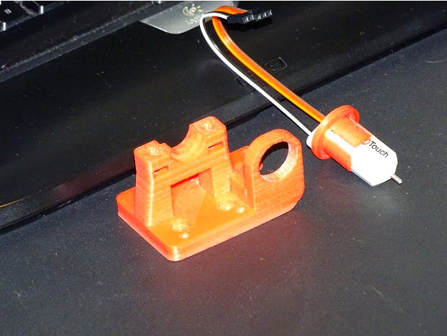
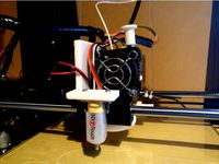
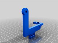
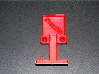
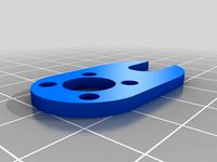
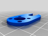
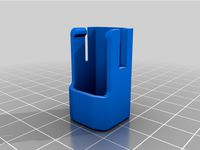
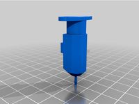
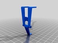
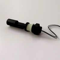
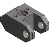
3DTouch Sensor adapter for e3d clamp by Draxan
by Thingiverse
Last crawled date: 3 years ago
If You want to use this e3d Mount You can use that adapter for Your 3DTouch sensor - https://www.thingiverse.com/thing:1695758
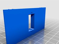
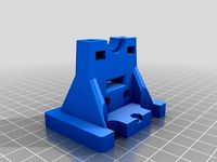
And there is a front part - http://www.thingiverse.com/thing:2172476
!!! Hole its not square, check it please before forcing sensor in it !!!
!!! its 18mm version !!!
If anyone need the sensor like this You can order GENUINE 3DTouch sensor here : http://ali.pub/ldh23
Or GENUINE BLTouch if You prefer is here: http://ali.pub/1f5veq
Or cheapest one here : http://ali.pub/1h7ghd
Later I try to remix that e3d mount for proper 3dtouch mounting point.
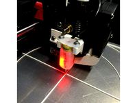
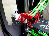
PS. my parts in action ;) - https://youtu.be/cJ1K7rZsdtY
PS2 . sendor in action :) - https://youtu.be/HdLyox9N8CE
==============================================================================================================================================
==================================================================================================================================
!!! ALL THANKS GOING TOO - http://www.thingiverse.com/OderWat/about !!!
!!! OderWat IS THE ONE THAT MAKE IS POSSIBLE !!!
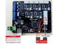
It uses the "LED pin" which is an unused pin on the A8 (using the stock 5 button 2004 LCD). That is the third wire counted from below (where the red marker is on the cable). I simply spliced the cable and cut that wire. This will be the servo signal (yellow).
On the A6, you may use wire no. 10 (the one on the other side to the red marked wire) and pin 17 in firmware the but you will lose the buzzer. I think one could use wire no. 7 and FW pin 29 but I could not yet verify that because I don't have an A6 display available.
The +5V (red) and GND (brown/black) are available at the z-end-stop connector as is the signal itself (white).
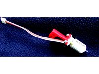
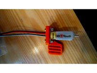
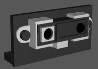
You can simply connect the black and brown wire of the sensor to the GND from the z-end-stop socket. This leaves you with 4 instead of 5 wires from the sensor to the board. On the first of the second two images you can see how I used some patch cables and a wire clamp to draft the connection at the board. In the second of the two images you can see the wiring at the sensor.
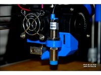
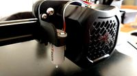
After everything worked well I have chosen an old usb mouse cable. Those have exactly 4 wires. I used green for the sensor, red for +5v, black for GND and yellow for the servo signal (originating from the LCD cable). I crimped a fitting connector for the z-end-stop socket and a single connector for the connection to the spliced LCD cable. I also soldered the other end of those 4 wires directly to the PCB inside of the sensor. Soldering is not needed and can be a pain. Beware not to destroy your sensor if you do it. You can see the result in the last three images.
Setting up SkyNet3D / Marlin (the firmware) is pretty straightforward. Besides the entries for the auto bed levelling you need to make the following entries:
define BLTOUCH
define SERVO0_PIN 27
define X_PROBE_OFFSET_FROM_EXTRUDER -20
define Y_PROBE_OFFSET_FROM_EXTRUDER -15
define Z_PROBE_OFFSET_FROM_EXTRUDER 0
define Z_MIN_PROBE_ENDSTOP_INVERTING false
I also used:
define Z_CLEARANCE_DEPLOY_PROBE 5
define Z_CLEARANCE_BETWEEN_PROBES 5
define LEFT_PROBE_BED_POSITION 20
define RIGHT_PROBE_BED_POSITION 200
define FRONT_PROBE_BED_POSITION 20
define BACK_PROBE_BED_POSITION 200
After mounting and uploading the new firmware you can test you sensor:
M280 P0 S10 ; pushes pin down
M280 P0 S90 ; drags pin up
M280 P0 S120 ; does selftest (pin up/down continuously)
M280 P0 S160 ; reset alarm
M280 P0 S60 ; switch triggering test mode
; move pin at the sensor up or down manually
M119 ; reports state of the endstop
; pin up (LED on) z_min should read TRIGGERED
; pin down (LED off) z_min should read open
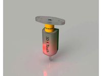
If your sensor does not selftest but blinks directly or after some few alternating motions you need to adjust the screw in the top of the sensor. One of the allen wrenches which are part of the printer does fit right in. Lose the screw until the light went off, then fasten the screw until it is lit again. I needed some time to find the sweet sport. Using selftest and reset alarm until it worked well.
Finally you can try a G28 command. If everything is OK it will probe twice in the middle of the bed. The tip will go down and up again as soon it touches the surface of the bed. If not you need to check cables and settings.
To adjust the z offset I use the following easy and pretty failsaife procedure:
; preheat for working temperatures
(M502 ; optionally reset to firmware settings)
M851 Z0 ; reset any z-offset
G28 ; home all
G1 X110 Y110 ; move nozzle in center
; now move your nozzle manually onto the bed such that it (strongly) grips paper.
G92 Z0 ; tell the printer that this is Z = 0
G30 X110 Y110 ; move the sensor over the center and let it trigger
; note what z position G30 reports, that, negated, is your z offset
M851 Z-1.23 ; register that z offset (here 1.23 as example)
M500 ; store those values into the EEPROM
You may want to do some G30 X110 Y110 commands to validate how well your sensor works. It should report the same values +/- 0.0x.
You can also enable Z_MIN_PROBE_REPEATABILITY_TEST in the firmware and use M48 L10 P8 V4 to let it test repeatability at the same point with a lot of fake movement in between probes.
There are occasions where the sensor after power on gives an error with the G28 command for no obvious reason. I found that the sequence:
M280 P0 S160 ; Reset 3D-Touch
G4 P500
M280 P0 S10 ; Pin out
G4 P500
M280 P0 S90 ; Pin back
G4 P500
Before the G28 command will reset the sensor in a way that it will alway (tm) work.
UPDATE: I added an alternative design "Distant" for the excellent "Mistral 2" cooling fanduct. This needs slightly changed firmware settings as follows:
define X_PROBE_OFFSET_FROM_EXTRUDER -26
define RIGHT_PROBE_BED_POSITION 200
And there is a front part - http://www.thingiverse.com/thing:2172476
!!! Hole its not square, check it please before forcing sensor in it !!!
!!! its 18mm version !!!
If anyone need the sensor like this You can order GENUINE 3DTouch sensor here : http://ali.pub/ldh23
Or GENUINE BLTouch if You prefer is here: http://ali.pub/1f5veq
Or cheapest one here : http://ali.pub/1h7ghd
Later I try to remix that e3d mount for proper 3dtouch mounting point.
PS. my parts in action ;) - https://youtu.be/cJ1K7rZsdtY
PS2 . sendor in action :) - https://youtu.be/HdLyox9N8CE
==============================================================================================================================================
==================================================================================================================================
!!! ALL THANKS GOING TOO - http://www.thingiverse.com/OderWat/about !!!
!!! OderWat IS THE ONE THAT MAKE IS POSSIBLE !!!
It uses the "LED pin" which is an unused pin on the A8 (using the stock 5 button 2004 LCD). That is the third wire counted from below (where the red marker is on the cable). I simply spliced the cable and cut that wire. This will be the servo signal (yellow).
On the A6, you may use wire no. 10 (the one on the other side to the red marked wire) and pin 17 in firmware the but you will lose the buzzer. I think one could use wire no. 7 and FW pin 29 but I could not yet verify that because I don't have an A6 display available.
The +5V (red) and GND (brown/black) are available at the z-end-stop connector as is the signal itself (white).
You can simply connect the black and brown wire of the sensor to the GND from the z-end-stop socket. This leaves you with 4 instead of 5 wires from the sensor to the board. On the first of the second two images you can see how I used some patch cables and a wire clamp to draft the connection at the board. In the second of the two images you can see the wiring at the sensor.
After everything worked well I have chosen an old usb mouse cable. Those have exactly 4 wires. I used green for the sensor, red for +5v, black for GND and yellow for the servo signal (originating from the LCD cable). I crimped a fitting connector for the z-end-stop socket and a single connector for the connection to the spliced LCD cable. I also soldered the other end of those 4 wires directly to the PCB inside of the sensor. Soldering is not needed and can be a pain. Beware not to destroy your sensor if you do it. You can see the result in the last three images.
Setting up SkyNet3D / Marlin (the firmware) is pretty straightforward. Besides the entries for the auto bed levelling you need to make the following entries:
define BLTOUCH
define SERVO0_PIN 27
define X_PROBE_OFFSET_FROM_EXTRUDER -20
define Y_PROBE_OFFSET_FROM_EXTRUDER -15
define Z_PROBE_OFFSET_FROM_EXTRUDER 0
define Z_MIN_PROBE_ENDSTOP_INVERTING false
I also used:
define Z_CLEARANCE_DEPLOY_PROBE 5
define Z_CLEARANCE_BETWEEN_PROBES 5
define LEFT_PROBE_BED_POSITION 20
define RIGHT_PROBE_BED_POSITION 200
define FRONT_PROBE_BED_POSITION 20
define BACK_PROBE_BED_POSITION 200
After mounting and uploading the new firmware you can test you sensor:
M280 P0 S10 ; pushes pin down
M280 P0 S90 ; drags pin up
M280 P0 S120 ; does selftest (pin up/down continuously)
M280 P0 S160 ; reset alarm
M280 P0 S60 ; switch triggering test mode
; move pin at the sensor up or down manually
M119 ; reports state of the endstop
; pin up (LED on) z_min should read TRIGGERED
; pin down (LED off) z_min should read open
If your sensor does not selftest but blinks directly or after some few alternating motions you need to adjust the screw in the top of the sensor. One of the allen wrenches which are part of the printer does fit right in. Lose the screw until the light went off, then fasten the screw until it is lit again. I needed some time to find the sweet sport. Using selftest and reset alarm until it worked well.
Finally you can try a G28 command. If everything is OK it will probe twice in the middle of the bed. The tip will go down and up again as soon it touches the surface of the bed. If not you need to check cables and settings.
To adjust the z offset I use the following easy and pretty failsaife procedure:
; preheat for working temperatures
(M502 ; optionally reset to firmware settings)
M851 Z0 ; reset any z-offset
G28 ; home all
G1 X110 Y110 ; move nozzle in center
; now move your nozzle manually onto the bed such that it (strongly) grips paper.
G92 Z0 ; tell the printer that this is Z = 0
G30 X110 Y110 ; move the sensor over the center and let it trigger
; note what z position G30 reports, that, negated, is your z offset
M851 Z-1.23 ; register that z offset (here 1.23 as example)
M500 ; store those values into the EEPROM
You may want to do some G30 X110 Y110 commands to validate how well your sensor works. It should report the same values +/- 0.0x.
You can also enable Z_MIN_PROBE_REPEATABILITY_TEST in the firmware and use M48 L10 P8 V4 to let it test repeatability at the same point with a lot of fake movement in between probes.
There are occasions where the sensor after power on gives an error with the G28 command for no obvious reason. I found that the sequence:
M280 P0 S160 ; Reset 3D-Touch
G4 P500
M280 P0 S10 ; Pin out
G4 P500
M280 P0 S90 ; Pin back
G4 P500
Before the G28 command will reset the sensor in a way that it will alway (tm) work.
UPDATE: I added an alternative design "Distant" for the excellent "Mistral 2" cooling fanduct. This needs slightly changed firmware settings as follows:
define X_PROBE_OFFSET_FROM_EXTRUDER -26
define RIGHT_PROBE_BED_POSITION 200
Similar models
thingiverse
free
Anet A8 3D-Touch Mount by OderWat
...d this: http://www.geeetech.com/forum/viewtopic.php?f=27&t=18263
thanks to "tobi as" for the wiring overview image!
thingiverse
free
FLSUN SuperRacer Servo Finish Flag mount by voltNik
...
g1 z+5 e-3 f3000
m280 p0 s60
m280 p0 s120
m280 p0 s60
m280 p0 s120
m280 p0 s60
m280 p0 s120
m280 p0 s60
m280 p0 s120
m280 p0 s60
thingiverse
free

GEEETech i3B: Firmware by Luca_Benedetto
...d (reset/autotest/pin down/pin up).
in configuration.h i’ve put step_per_unit for t8, but you can found also the old line for m8.
thingiverse
free
Sunhokey Prusa i4 BLTouch Setup Marlin 1.1.0 RC8 Firmware by Middleman
....
now you are ready to print with the bltouch!
join the prusa i4 facebook group: https://www.facebook.com/groups/573076312852368
thingiverse
free
Anet A6 BLTouch/3DTouch mount (front) by thvranken
...isplay or with command m851) and saved to the eeprom (using the display or with command m500), in my case, this was around -2 mm.
thingiverse
free
Anet A8 3DTouch/BLTouch Auto Leveling Sensor Bracket by JMadison
...keeps going until you do pin up/down or release alarm
m280 p0 s160 ; release alarm
hardware: (2) m3 x 8, (2) m3 x 12, (4) m3 nuts
thingiverse
free
Anet A8 Sensor Bracket 12mm and 18mm by Leo_N
...not sensor related but the z homing speed was too fast for my taste. to have it move slower use:
define homing_feedrate_z (4*60)
thingiverse
free

Reach3D BLTouch Setup Marlin 1.1.0 RC8 by Middleman
...alue you entered for z-offset
do a g28
do a g29, it will probe 9 points on your bed.
now you are ready to print with the bltouch!
thingiverse
free
3dtouch/bltouch mount for Ender 3 v2 by streefland
...ach printer individually. marlin needs to be configured with the following offsets:
#define nozzle_to_probe_offset { -39, -9, 0 }
thingiverse
free
3D/BL touch mount for Anet A6 by ithinuel
...ly 3 grid points on a linear bed levelling.
i am printing on a borosilicate glass bed, i don't know if more point are needed.
Draxan
thingiverse
free
e3d v6 Cable Chain mount by Draxan
....
chains i using in my build - http://www.thingiverse.com/thing:1905344
ps. my parts in action ;) - https://youtu.be/cj1k7rzsdty
thingiverse
free
Anet A8 Z wobble mod by Draxan
...
edit: new video to show movement on rods - https://youtu.be/blmfq-ksvws
ps. my parts in action ;) - https://youtu.be/cj1k7rzsdty
thingiverse
free
e3d v6 Clamp with chain holder + LED strip by Draxan
...s without cable chain if you want, just dont print chain mount part :)
ps. my parts in action ;) - https://youtu.be/cj1k7rzsdty
thingiverse
free

Anet A8 hot bed IGUS holders/clamps by Draxan
... push bearings in untill they snap in place. use some force to do it :)
ps. my parts in action ;) - https://youtu.be/cj1k7rzsdty
thingiverse
free
Anet A8 Z wobble - Rotated by Tannerswe
...version has the holes rotated 45 degrees. original by draxan see instructions...
thingiverse
free
Anti wobble Z-Axis for stock Anet A8 X Axis mounts by ttreu
...by ttreu thingiverse remix for stock anet_a8_x-axis_mounts. original by draxan see instructions...
thingiverse
free

Updated Anet A6 A8 Z Axis motor hold down mounts (4 versions) by Lanzecki
...step (for side mounting. see the pictures. thanks to draxan for details of issues with the a8. designed to...
3Dtouch
thingiverse
free
3DTouch Holder by sopak
...3dtouch holder by sopak
thingiverse
universal 3dtouch and bltouch mount holes are 3mm with 5mm distance.
thingiverse
free
3DTouch binder by zull
...3dtouch binder by zull
thingiverse
platform for 3dtouch sensor from geeetech for geeetech i3 pro b with mk8 extruder
thingiverse
free
3DTouch Shield (Cover) by mardun
...e
shield/cover for 3dtouch to minimize led light. i tried to use other (mainly for bltouch) but they will not fit to my 3dtouch.
thingiverse
free
3DTouch model (STEP) by Leoliss
...retract - move needle in 3.8mm up. and yes, this is 3dtouch. bltouch have slightly different dimensions.
stl is just for preview.
thingiverse
free
GEEETech E3D v6 with 3DTouch by Minims
...geeetech e3d v6 with 3dtouch by minims
thingiverse
e3d v6 with 3dtouch for metal carriage
thingiverse
free
3dTouch probe model by deadcat
...e model by deadcat
thingiverse
this a fusion360 model of the 3dtouch to use when designing mounts. i have also included the stl.
thingiverse
free
3DTouch lock by markost
...he pin while printing and started breaking my prints and due potential damage to the sensor itself, i designed a pin lock for it.
thingiverse
free

BIQU B1 3DTouch mount by iNardex
...s not good for 3dtouch sensor.
designed for and tested with a 3dtouch v3.0.
i added the fusion360 project for any customizations.
thingiverse
free

Suport 3Dtouch BLTouch Graber Tec3d
...suport 3dtouch bltouch graber tec3d
thingiverse
suporte para fixar 3dtouch ou bltouch na extrusora graber i3 da tec3d.
thingiverse
free
3DTouch\BLTouch Holder for MiniTree T3 by zekeda1
...3dtouch\bltouch holder for minitree t3 by zekeda1
thingiverse
simple holder of 3dtouch\bltouch for minitree t3 3d printer.
E3D
turbosquid
$23

E3D - Google Home
... 3d model e3d - google home for download as max, obj, and c4d on turbosquid: 3d models for games, architecture, videos. (1192509)
cg_studio
free

e3d model
...e3d model
cgstudio
- e 3d model, royalty free license available, instant download after purchase.
turbosquid
$2
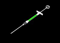
Syringe C4D (E3D Ready)
...lty free 3d model syringe c4d (e3d ready) for download as c4d on turbosquid: 3d models for games, architecture, videos. (1336720)
turbosquid
$12
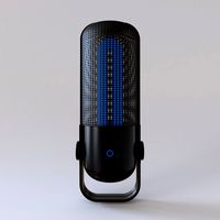
Microphone USB E3D and C4D
...ree 3d model microphone usb e3d & c4d for download as c4d on turbosquid: 3d models for games, architecture, videos. (1568216)
turbosquid
$29

E3D - OnePlus 6 Black
...model e3d - oneplus 6 black for download as max, obj, and c4d on turbosquid: 3d models for games, architecture, videos. (1358534)
turbosquid
$29

E3D - Motorola One 2018
...del e3d - motorola one 2018 for download as max, obj, and c4d on turbosquid: 3d models for games, architecture, videos. (1358533)
turbosquid
$29
E3D - Disney MagicBands 2
...l e3d - disney magicbands 2 for download as max, obj, and c4d on turbosquid: 3d models for games, architecture, videos. (1355515)
turbosquid
$29

E3D - Samsung Z4 Smartphone
...e3d - samsung z4 smartphone for download as max, obj, and c4d on turbosquid: 3d models for games, architecture, videos. (1182179)
turbosquid
$23

E3D - Razer Phone model
...del e3d - razer phone model for download as max, obj, and c4d on turbosquid: 3d models for games, architecture, videos. (1231207)
turbosquid
$23

E3D - Alcatel Idol 5
... model e3d - alcatel idol 5 for download as max, obj, and c4d on turbosquid: 3d models for games, architecture, videos. (1212799)
Sensor
3d_export
free

parking sensor
...parking sensor
3dexport
car parking sensor
turbosquid
$1
Sensor
... available on turbo squid, the world's leading provider of digital 3d models for visualization, films, television, and games.
3d_export
$5
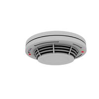
Smoke sensor
...port
smoke sensor, can be an impressive element for your projects. easy to use, realistic image, low polygon, quality materials.
3d_export
$5
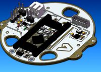
Air Quality Sensor v1
...air quality sensor v1
3dexport
air quality sensor v1
3d_export
$15
float sensor
...e up render. - all parts and materials are logically named. other formats ================= - collada (.dae) - autodesk fbx - obj
turbosquid
$26
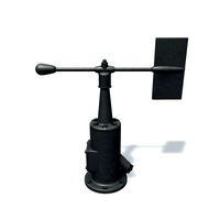
Wind sensor C
...free 3d model wind sensor c for download as 3ds, obj, and fbx on turbosquid: 3d models for games, architecture, videos. (1328943)
turbosquid
$26
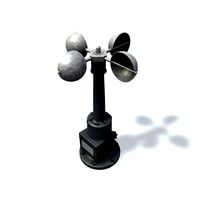
Wind sensor B
...free 3d model wind sensor b for download as 3ds, obj, and fbx on turbosquid: 3d models for games, architecture, videos. (1328168)
3d_export
$5
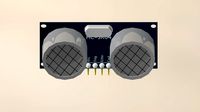
ultrasound sensor
...ivers convert ultrasound into electrical signals, and transceivers can both transmit and receive ultrasound. export in: -obj -fbx
3ddd
free
Вытяжка Shindo pallada sensor
... вытяжка
вытяжка shindo pallada sensor. в двух размерах - 600 и 900. текстуры в комплекте.
turbosquid
$52
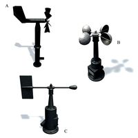
Wind sensor A B C
...
royalty free 3d model wind sensor a b c for download as fbx on turbosquid: 3d models for games, architecture, videos. (1408406)
Clamp
3d_export
$11

clamp
...clamp
3dexport
clamp
3ddd
free

Clamp
... enricо zanolla , капитоне
дизайнерenrico zanollмодель clamp
3ddd
$1

Clamp
...ricо zanolla , капитоне
дизайнеры
enrico zanolla
andrea di filippo
модель clamp
dzstudio
3d_export
free
clamp
...clamp
3dexport
simple clamp model, more free 3d models here:
3d_export
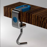
$5
clamping handle
...clamping handle
3dexport
clamping handle
3ddd
$1

Clamp / DZstudio
... dzstudio , капитоне
люстра clamp от dzstudio/enrico zanolla(италия).
3ddd
$1
Светильник Clamp
...светильник clamp
3ddd
clamp
стеганый светильник clamp в двух цветах в черном и белом.
turbosquid
$29
clamp
...ty free 3d model clamp for download as 3ds, obj, c4d, and fbx on turbosquid: 3d models for games, architecture, videos. (1442049)
turbosquid
$29
clamp
...ty free 3d model clamp for download as 3ds, obj, c4d, and fbx on turbosquid: 3d models for games, architecture, videos. (1442041)
3d_export
$5
Clamp-14
...clamp-14
3dexport
3d model of clamp name 14
Adapter
3d_export
$10

Adapter 3D Model
...adapter 3d model
3dexport
adapter
adapter 3d model mur 20260 3dexport
archive3d
free
Adapter socket 3D Model
...dapter socket adapter
adapter socket n090211 - 3d model (*.3ds) for interior 3d visualization.
turbosquid
$400

cell adaptation
...
royalty free 3d model cell adaptation for download as blend on turbosquid: 3d models for games, architecture, videos. (1701655)
archive3d
free
Adapter 3D Model
...ups pc equipment
adapter extron n180813 - 3d model (*.gsm+*.3ds) for interior 3d visualization.
turbosquid
$5

usb adapter
...royalty free 3d model usb adapter for download as ige and stl on turbosquid: 3d models for games, architecture, videos. (1582234)
turbosquid
$15
Power adapter
...free 3d model power adapter for download as max, obj, and fbx on turbosquid: 3d models for games, architecture, videos. (1510024)
turbosquid
$8
USB adapter
...e 3d model usb adapter for download as max, fbx, obj, and dwg on turbosquid: 3d models for games, architecture, videos. (1713542)
turbosquid
$30
adapter.3ds
... available on turbo squid, the world's leading provider of digital 3d models for visualization, films, television, and games.
turbosquid
$15
Nokia Adapter
... available on turbo squid, the world's leading provider of digital 3d models for visualization, films, television, and games.
turbosquid
$15
Universal adapter
... available on turbo squid, the world's leading provider of digital 3d models for visualization, films, television, and games.