Thingiverse
3D Printer EPS12V Power Supply Conversion by Vixiea
by Thingiverse
Last crawled date: 4 years, 9 months ago
------PREFACE------
This document involves modifying the 12 volt power wires of your 3D printer. It assumes that you understand that mixing these wires up could cause irreparable damage to your 3D printer and likely void the warranty. The document was made using an Anycubic i3 Mega S but, with modification, can be applied to any 3D printer that runs off 12 volts DC. If you choose to do this you take your fate into your own hands, don't complain that I broke your printer.
------BACKGROUND------
I got tired of the noise and inefficiency of the standard power supply on my i3 Mega S so I decided it was time to replace it. Since the unit is 12 volts I decided it would be fun (read mad scientist) to convert it to run off the EPS12V, or CPU, connector of a PC power supply.
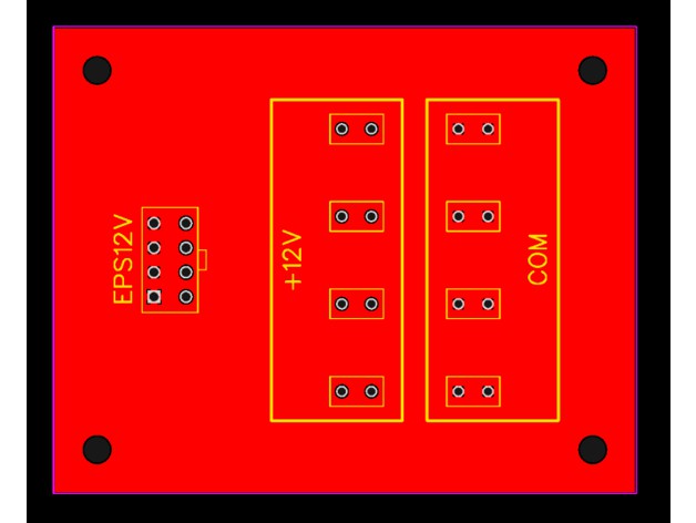
A quick PCB design later I had a simple 80x100 board that took the 8 pin, 336 watt, EPS12V connecter and combined it into a single +12 and COM rail with 4 blade terminals each, and with a quick rewiring job I was ready to go. Before I get to the results of the conversion here are a few metrics I took with the stock supply, one note is that peak watts and VA were taken with the printer not moving but both heaters on full blast.
Stock Running Power Factor: 0.52 (ouch)
Stock Running Watt Average: 130
Stock Heating Watt Peak: 230
Stock Running VA Average: 230
Stock Heating VA Peak: 333
As you can see the power factor is quite awful and as a result the apparent power of the machine is much higher. Where I live I'm not charged for apparent power, yet, but for those of you who are...ouch.
Onto the PC supply:
PC Running Power Factor: 0.74
PC Running Watt Average: 116
PC Heating Watt Peak: 192
PC Running VA Average: 147
PC Heating VA Peak: 194
Right off the cuff the power factor while running is markedly better which results in much better apparent power numbers. Secondly, the PC supply has power factor correction built in so the power factor is near unity (1.00) when running both heaters.
Overall I'd say this is a worthwhile upgrade to do to any 3D printer that runs off 12 volts and uses those generic power supplies.
------FILES AND PARTS------
Contained in the thing files are a zip of the gerber files that most PCB shops will need along with a bill of materials in CSV format.
For my boards I used https://jlcpcb.com/ and was able to upload the zip file directly to their site. If you choose to go with JLCPCB you shouldn't have to do anything else to the PCB before you order it, but if you want to change the color go for it! It took about 8 business days for me to receive my PCBs.
For the PCB you'll need the following:
1x https://www.digikey.com/en/products/detail/molex/0039281083/61407
8x https://www.digikey.com/en/products/detail/te-connectivity-amp-connectors/1742188-1/6810736
For the wires you'll need the following:
8x https://www.digikey.com/en/products/detail/te-connectivity-amp-connectors/3-350819-2/288028
4x sets of red and black wires, you can reuse your existing printer wiring or purchase new. If you're going to purchase new I recommend 16 AWG 600V 200C wire:https://www.amazon.com/dp/B07CMYVF3J/ref=cm_sw_em_r_mt_dp_QReYFb2ESZQZD
1x PC power supply with an 8 pin EPS12V, or CPU, power connector. Must be able to supply the full 336 watts over the cable.
1x PC power supply jumper: https://www.amazon.com/dp/B01N8Q0TOE/ref=cm_sw_em_r_mt_dp_2rfYFb3Y3XTFV
Finally you'll need a way to mount it in your specific printer, for my i3 Mega S I scaled this file in Cura to 80x100mm in X and Y and left Z at 100%
The fit isn't perfect but it gets the job done, I printed this in PLA.https://www.thingiverse.com/thing:2161451
To attach the board I used 2 M3x20 bolts, 2 M3 washers, and 2 M3 nuts.
------TOOLS------
You'll need the following to assemble and mount the PCB in an i3 Mega S:
Spade Terminal Crimper -OR- Needle Nose Pliers and Slip Jaw Pliers
Soldering Iron
Solder
Wire Stripper -OR- Wire Cutters
Metric Hex Wrenches
Drill with 3.5mm or 1/8" Drill Bit
2.5 mm or 1/8" Slotted Screw Driver
Isopropanol Pads/Swabs
Multimeter
P2 Phillips Screwdriver
------INSTRUCTIONS------
Before I begin I want to discuss crimping the blade connectors. Make sure you pull test each wire, giving it a good tug. If the wire moves or comes out you didn't crimp it hard enough. In my case I don't have the correct crimper so I used a needle nose and slip jaw pliers and squeezed the daylights out of the connector with the needle nose while using the slip jaw on the needle nose for more force.
The crimp point on the connectors is the neck.
Solder all the required parts onto the PCB making sure that the tab on the EPS12V connector faces toward the +12V mark.
Clean the solder joint with isopropanol pads or swabs.
Inspect all the solder joints, make sure solder has flowed into each hole around the component.
Using a multimeter set to continuity, or ohms, check each pin in the EPS12V connector. The 4 pins closest to the +12V blade terminals should read 0 resistance while also reading open circuit to the COM blade terminals. The 4 pins closest to the edge of the board should read 0 resistance to the COM blade terminals while also reading open circuit to the +12V blade terminals.
Snip off sharp solder points with a wire cutter if continuity checks out.
Using the PCB holes as a guide, drill a hole through two of the corners of the bracket you printed along the 100mm side.
Unplug and flip your i3 Mega S on its back, take care that the bed doesn't slam into the table.
Remove the two M3 screws holding the wire bar across the bottom cover in place, leave the wire attached to the bar to hang freely.
Remove the 8 M3 screws holding your bottom cover on and set it aside.
TAKE PICTURES OF ALL THE WIRE CONNECTIONS INSIDE JUST IN CASE!
Unscrew all of the connections to the stock power supply.
Remove the 4 M3 screws holding the power supply in place, these are found under the Y axis on the outside of the case. Make sure to hold onto the power supply as it will fall.
Remove the power supply.
Remove the screws holding the AC plug in place and remove the AC plug.
Insert your two M3x20 bolts through the two power supply screw holes closest to the screen.
Using the holes you drilled in step 6, slide your bracket X side down into the case. You may need to rotate the bolts so they cut a thread through the plastic.
Slide your PCB into place with the COM blade terminals closest to the motherboard.
Secure the PCB to the M3 bolts using the M3 washers and M3 nuts.
Step 19 will be different depending on your wiring and and mosfet situation, in my case I have mosfets but didn't modify the wires going to the mainboard so I was able to reuse them for all my connections.
19A If you are NOT using mosfets for your heated bed and hotend you can cut the spade connectors for the old power supply off your red and black wires, crimp on the new blade connectors, and plug the red wires into +12V and the black wires into COM. To make the remaining 4 blade connectors safe simply slide on an uncrimped blade connector.
19B If you ARE using mosfets for your heated bed and hotend unscrew the red and black power supply wires from your mainboard and pull them free, remove the protective black wire sheath, lay them out so they reach from the mainboard connectors to your EPS12V connector, and cut them at that point.
You should now have 8 sets of wires, 4 with spade terminals on one end and 4 with soldered ends. For the cables with the spade terminals; crimp blade connectors on the other end and attach them to your mosfets, making sure that red goes to the +12V rail and black goes to COM. For the cabled with the soldered ends its the same process except you'll reinsert the soldered ends back into the mainboard.
As in 19A if you have any unused blade terminals, cover them with uncrimped blade connectors to make them safe.
Make it pretty! Cable manage things with all the new room!
Route your EPS12V wire through the AC plug hole and plug it in.
Plug the PC power supply jumper onto the 24 pin cable.
If the PC power supply has a switch, set it to off and plug in the PC power supply.
Before flipping the switch, take one last look at the pictures I have here and make sure nothing is backwards!
Flip the switch on and make sure your printer powers on.
Flip the switch off, disconnect the power, and close up the printer.
Re-level your bed and Enjoy!
This document involves modifying the 12 volt power wires of your 3D printer. It assumes that you understand that mixing these wires up could cause irreparable damage to your 3D printer and likely void the warranty. The document was made using an Anycubic i3 Mega S but, with modification, can be applied to any 3D printer that runs off 12 volts DC. If you choose to do this you take your fate into your own hands, don't complain that I broke your printer.
------BACKGROUND------
I got tired of the noise and inefficiency of the standard power supply on my i3 Mega S so I decided it was time to replace it. Since the unit is 12 volts I decided it would be fun (read mad scientist) to convert it to run off the EPS12V, or CPU, connector of a PC power supply.
A quick PCB design later I had a simple 80x100 board that took the 8 pin, 336 watt, EPS12V connecter and combined it into a single +12 and COM rail with 4 blade terminals each, and with a quick rewiring job I was ready to go. Before I get to the results of the conversion here are a few metrics I took with the stock supply, one note is that peak watts and VA were taken with the printer not moving but both heaters on full blast.
Stock Running Power Factor: 0.52 (ouch)
Stock Running Watt Average: 130
Stock Heating Watt Peak: 230
Stock Running VA Average: 230
Stock Heating VA Peak: 333
As you can see the power factor is quite awful and as a result the apparent power of the machine is much higher. Where I live I'm not charged for apparent power, yet, but for those of you who are...ouch.
Onto the PC supply:
PC Running Power Factor: 0.74
PC Running Watt Average: 116
PC Heating Watt Peak: 192
PC Running VA Average: 147
PC Heating VA Peak: 194
Right off the cuff the power factor while running is markedly better which results in much better apparent power numbers. Secondly, the PC supply has power factor correction built in so the power factor is near unity (1.00) when running both heaters.
Overall I'd say this is a worthwhile upgrade to do to any 3D printer that runs off 12 volts and uses those generic power supplies.
------FILES AND PARTS------
Contained in the thing files are a zip of the gerber files that most PCB shops will need along with a bill of materials in CSV format.
For my boards I used https://jlcpcb.com/ and was able to upload the zip file directly to their site. If you choose to go with JLCPCB you shouldn't have to do anything else to the PCB before you order it, but if you want to change the color go for it! It took about 8 business days for me to receive my PCBs.
For the PCB you'll need the following:
1x https://www.digikey.com/en/products/detail/molex/0039281083/61407
8x https://www.digikey.com/en/products/detail/te-connectivity-amp-connectors/1742188-1/6810736
For the wires you'll need the following:
8x https://www.digikey.com/en/products/detail/te-connectivity-amp-connectors/3-350819-2/288028
4x sets of red and black wires, you can reuse your existing printer wiring or purchase new. If you're going to purchase new I recommend 16 AWG 600V 200C wire:https://www.amazon.com/dp/B07CMYVF3J/ref=cm_sw_em_r_mt_dp_QReYFb2ESZQZD
1x PC power supply with an 8 pin EPS12V, or CPU, power connector. Must be able to supply the full 336 watts over the cable.
1x PC power supply jumper: https://www.amazon.com/dp/B01N8Q0TOE/ref=cm_sw_em_r_mt_dp_2rfYFb3Y3XTFV
Finally you'll need a way to mount it in your specific printer, for my i3 Mega S I scaled this file in Cura to 80x100mm in X and Y and left Z at 100%
The fit isn't perfect but it gets the job done, I printed this in PLA.https://www.thingiverse.com/thing:2161451
To attach the board I used 2 M3x20 bolts, 2 M3 washers, and 2 M3 nuts.
------TOOLS------
You'll need the following to assemble and mount the PCB in an i3 Mega S:
Spade Terminal Crimper -OR- Needle Nose Pliers and Slip Jaw Pliers
Soldering Iron
Solder
Wire Stripper -OR- Wire Cutters
Metric Hex Wrenches
Drill with 3.5mm or 1/8" Drill Bit
2.5 mm or 1/8" Slotted Screw Driver
Isopropanol Pads/Swabs
Multimeter
P2 Phillips Screwdriver
------INSTRUCTIONS------
Before I begin I want to discuss crimping the blade connectors. Make sure you pull test each wire, giving it a good tug. If the wire moves or comes out you didn't crimp it hard enough. In my case I don't have the correct crimper so I used a needle nose and slip jaw pliers and squeezed the daylights out of the connector with the needle nose while using the slip jaw on the needle nose for more force.
The crimp point on the connectors is the neck.
Solder all the required parts onto the PCB making sure that the tab on the EPS12V connector faces toward the +12V mark.
Clean the solder joint with isopropanol pads or swabs.
Inspect all the solder joints, make sure solder has flowed into each hole around the component.
Using a multimeter set to continuity, or ohms, check each pin in the EPS12V connector. The 4 pins closest to the +12V blade terminals should read 0 resistance while also reading open circuit to the COM blade terminals. The 4 pins closest to the edge of the board should read 0 resistance to the COM blade terminals while also reading open circuit to the +12V blade terminals.
Snip off sharp solder points with a wire cutter if continuity checks out.
Using the PCB holes as a guide, drill a hole through two of the corners of the bracket you printed along the 100mm side.
Unplug and flip your i3 Mega S on its back, take care that the bed doesn't slam into the table.
Remove the two M3 screws holding the wire bar across the bottom cover in place, leave the wire attached to the bar to hang freely.
Remove the 8 M3 screws holding your bottom cover on and set it aside.
TAKE PICTURES OF ALL THE WIRE CONNECTIONS INSIDE JUST IN CASE!
Unscrew all of the connections to the stock power supply.
Remove the 4 M3 screws holding the power supply in place, these are found under the Y axis on the outside of the case. Make sure to hold onto the power supply as it will fall.
Remove the power supply.
Remove the screws holding the AC plug in place and remove the AC plug.
Insert your two M3x20 bolts through the two power supply screw holes closest to the screen.
Using the holes you drilled in step 6, slide your bracket X side down into the case. You may need to rotate the bolts so they cut a thread through the plastic.
Slide your PCB into place with the COM blade terminals closest to the motherboard.
Secure the PCB to the M3 bolts using the M3 washers and M3 nuts.
Step 19 will be different depending on your wiring and and mosfet situation, in my case I have mosfets but didn't modify the wires going to the mainboard so I was able to reuse them for all my connections.
19A If you are NOT using mosfets for your heated bed and hotend you can cut the spade connectors for the old power supply off your red and black wires, crimp on the new blade connectors, and plug the red wires into +12V and the black wires into COM. To make the remaining 4 blade connectors safe simply slide on an uncrimped blade connector.
19B If you ARE using mosfets for your heated bed and hotend unscrew the red and black power supply wires from your mainboard and pull them free, remove the protective black wire sheath, lay them out so they reach from the mainboard connectors to your EPS12V connector, and cut them at that point.
You should now have 8 sets of wires, 4 with spade terminals on one end and 4 with soldered ends. For the cables with the spade terminals; crimp blade connectors on the other end and attach them to your mosfets, making sure that red goes to the +12V rail and black goes to COM. For the cabled with the soldered ends its the same process except you'll reinsert the soldered ends back into the mainboard.
As in 19A if you have any unused blade terminals, cover them with uncrimped blade connectors to make them safe.
Make it pretty! Cable manage things with all the new room!
Route your EPS12V wire through the AC plug hole and plug it in.
Plug the PC power supply jumper onto the 24 pin cable.
If the PC power supply has a switch, set it to off and plug in the PC power supply.
Before flipping the switch, take one last look at the pictures I have here and make sure nothing is backwards!
Flip the switch on and make sure your printer powers on.
Flip the switch off, disconnect the power, and close up the printer.
Re-level your bed and Enjoy!