Thingiverse
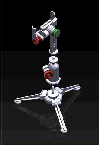
360 Universal Head with Tripod for Camera & Phone by Dr_Skycat
by Thingiverse
Last crawled date: 3 years ago
I have posted this under the name Skycat17. For unknown reasons I can no longer get into that account. So this designs is exactly the same for now, but may be updated in the future.
The files under Skycat17 (this one and a model of the Chrysler Building) are still available for download on Thingiverse. But I have no access to even see how many have downloaded or responded.
This three part assembly is comprised of:
The 360° Head (Main Body), with full 360 degree movement.
The Tripod.
The Phone Holder.
The Main Body consists of six parts + one 1/4 x 20 x 1.5" steel bolt and nut. A second 1/4 x 20 x 1" bolt is required for the Knob.
Body
Ball
Sleeve
Base
Knob
Knob Insert
360° HEAD
Step 1.
The steel bolt is inserted in the printed Ball prior to inserting it in the Body. Pushing the Ball and Bolt assembly to the top of the Body will require a bit of push, as it has to get past the inner retaining ridge.
Once the Ball with bolt is positioned, screw the sleeve onto the threaded end of the bolt.
Step 2.
Push the Base unit into the Body until you feel a slight click, as the small circular ridge registers into the small concentric groove inside the Body.
This might go a little easier if you slightly spread the Body open at the gap while pushing the Base into the Body.
Step 3.
Next insert the 1/4 x 20 x 1" bolt into the Knob, then insert the 1/4 x 20 nut into the Body and screw in the Knob/Bolt assembly.
Step 4. (optional)
Insert the Knob Insert into the Knob. This is both decorative and also helps to keep the bolt from sliding out of the Knob when it's not screwed into the nut.
To make the 360° Universal Head work more smoothly put the ball and bolt assembly into an electric drill and use sandpaper to smooth out the ball, prior to inserting it into the Head.
TRIPOD
The Tripod component consists of four parts and three 3mm x 22mm screws and one 1/4 x 20 x 1" flat head bolt.
Tripod Base
Leg (3 needed)
Step 1.
After printing the three Legs, clean up the pivot joint area that will contact the Tripod Base sockets.
Step 2.
Place the Legs in the Tripod Base sockets and secure by inserting the 3 mm x 22mm screw into the self threading holes using an allen wrench.
Step 3.
Screw the 1/4 x 20 x 1" screw into the Tripod Base as shown in the photo.
Note: Purchase rubber pads from:https://www.amazon.com/gp/product/B01LDLJF5K/ref=ppx_yo_dt_b_asin_title_o01_s00?ie=UTF8&psc=1
Place one of the self stick pads in the bottom of each foot pod to prevent slipping
PHONE HOLDER
The Phone Holder component consists of six parts and one 1/4 x 20 x 1.25" screw and one 4mm x 60mm screw.
Rotating Head Clamp - Right
Rotating Head Clamp - Left
Rotating Head Mast - Default (two taller sizes are included)
Rotating Head Clamp - Knob Large
Rotating Head Clamp - Knob Small
Rotating Head Mast Washer
Step 1.
After printing the Left and Right Clamp parts, file and sand the bottoms where the print supports were attached to make sure they slide easily into one another.
Before final assembly with the Knob and screw test them for free fit. As well, push the 4mm long screw through both Clamps holes back and forth to insure they are sliding freely.
Step 2.
Drop the 1/4 x 20 nut into the pocket in the Left Clamp.
Insert the1/4 x 20 x 1.5" bolt into the Rotating Head Clamp - Knob Large, then screw the Knob and Bolt assembly into the nut in the Left Clamp pocket.
This will prevent the 1/4 x 20 nut from falling out. Once the Right Clamp has been mated with the Left Clamp the nut will be trapped and unable to fall out.
Step 3.
Screw the 4mm x 60mm screw into the ridged end of the Small Knob until the screws end is flush with the flat surface.
Then, slide the Small Knob screw assembly into the flange on the Rotating Head Clamp - Right.
Continue screwing it until it bottoms inside the Small Knob and gently tighten it.
Step 4.
Drop the 4mm nut into the pocket in the Left Clamp, then screw the Right Clamp Knob Screw assembly into the Left Clamp.
Step 5.
Screw the Rotating Head Mast Default into the 1/4 x 20 screw protruding from the 360° head.
Step 6.
Unscrew the Rotating Head Clamp - Knob Large and bolt assembly. Then re-screw it through the Mast using the tabbed Rotating Head Mast Washer with the tab facing the bottom.
Hardware
Bolt - 1/4 x 20 x 1" (Hex Head)
Bolt - 1/4 x 20 x 1.25" (Hex Head)
Bolt - 1/4 x 20 x 1.5" (Hex Head)
Bolt - 1/4 x 20 x 1" (Flat Head) (allen or philips type)
Screw - 3mm x 22mm (allen head type)
Screw - 4mm x 60mm (allen or phillips type)
All the above screws can be obtained from different sources.
This source from the USA is from McMaster Carr: https://www.mcmaster.com/
Rubber Pads - https://www.amazon.com/gp/product/B01LDLJF5K/ref=ppx_yo_dt_b_asin_title_o01_s00?ie=UTF8&psc=1
Cement one to the bottom of each foot pad to prevent slipping
The 360° Universal Head is compatible with standard camera socket mounts.
Print Settings
Printer brand:
Prusa
Printer:
I3 MK3S
Rafts:
No
Supports:
Yes
Resolution:
0.2
Infill:
20%
Filament brand:
Prusament
Filament color:
Any
Filament material:
PLA
Notes:
I have printed all the parts using a Prusa MK3S, a Prusa Mini, and an Ender 3.
All the above printers gave great results, using .2mm .2.5mm and .3mm.
For most of the parts I would suggest .2mm with .15 on the smaller parts and .3mm on the extra tall Mast.
Refer to the photos for orientation on the printer plate as well as how supports and brims are used where they're needed.
Similar models
thingiverse
free

360 Universal Head by Dr_Skycat
...he above screws can be obtained from different sources.
this source from the usa is from mcmaster carr: https://www.mcmaster.com/
thingiverse
free

Tripod to camera adjuster knob by anthonywob
...er knob to tighten the tripod to camera body.
use with:
1x 1/4-20 x 1" bolt
2x standard washer
1x lock washer
2x 1/4-20 nuts
thingiverse
free

Panasonic Lumix GX800 (GX850, GF9) camera grip by MACPET
...; into "main" body with round hole pointing up.
3) insert "block" into "main" body.
4) insert bolt.
thingiverse
free

articulating mount by Inventor369
... mount by inventor369
thingiverse
print 2 clamps, two ball mounts, one knob, and assemble with 1/2" nut,bolt, and a spring.
thingiverse
free

GoPro male tripod end by kirkendsley
...nut. assembly is simple, just screw the bolt into the threaded mount, then use a dab of superglue to fix the nut inside the ring.
thingiverse
free

MINI TRIPODS (3mm SCREW) & UNIVERSAL PHONE MOUNT by mck_maah
...ad clamp or
-m3 x 40mm allen bolt - for the ballhead clamp if you no use tripod_knob
-m3 nut - for the tripod_knob or tripod_base
thingiverse
free

Small Clamp for Modular Clamping System by Erich_with_an_H
...ghtly. the upside is that, if the edges wear until the fit is too loose, you can just tighten down the screws to restore the fit.
thingiverse
free

Goluk T3 Dashcam Tripod Adapter by OrbitalToast
...uot; flat head bolt.
slide the nut into the hex-shaped hole in the adapter and secure with the flathead bolt on the opposite end.
thingiverse
free

Heavy Duty C Clamp Tripod for Camera and Light
...lampspigot" witch can be enforced with an m3x30 countersink screw.
please considere leaving me a tip if you like the design.
thingiverse
free

Adjustable Tripod Phone Mount by dhulihan
...20 wingnut or jig knob
1x 1/4" x 20 hex-head bolt. this should be at least 0.75" longer than the width of your phone.
Skycat
thingiverse
free

Another Chrysler Building by Dr. Skycat by Skycat17
...e stl files show the building and parts in a sideways orientation. all the stl files should be oriented vertical in your slicer.
3dwarehouse
free

skycat
...skycat
3dwarehouse
skycat its coo #wbhs
3dwarehouse
free

Flying Carrier
...this flying aircraft carrier comes from a massively altered skycat model by smike. this airship was designed for the...
Dr
design_connected
$16

Dr. Yes
...dr. yes
designconnected
kartell dr. yes computer generated 3d model. designed by starck, philippe.
3ddd
$1
kartell dr. glob
...kartell dr. glob
3ddd
kartell
kartell dr. glob
3d_export
$10
Dr Fate
...dr fate
3dexport
stl for print
turbosquid
$30

Dr. Feelgood
... available on turbo squid, the world's leading provider of digital 3d models for visualization, films, television, and games.
turbosquid
$24

Dr Spark
... available on turbo squid, the world's leading provider of digital 3d models for visualization, films, television, and games.
turbosquid
$1

Dr No Octofuzz
... available on turbo squid, the world's leading provider of digital 3d models for visualization, films, television, and games.
turbosquid
$1

Dr No MadFly
... available on turbo squid, the world's leading provider of digital 3d models for visualization, films, television, and games.
turbosquid
$1

Dr No Kafuzz
... available on turbo squid, the world's leading provider of digital 3d models for visualization, films, television, and games.
cg_studio
$18
Dr Sonderbar3d model
...design chair designer dr sonderbar
.max - dr sonderbar 3d model, royalty free license available, instant download after purchase.
3ddd
$1
agape dr
...agape dr
3ddd
agape , ванна
agape bionic models
Tripod
archibase_planet
free
Tripod
...tripod
archibase planet
tripod staff state stand
tripod - 3d model for interior 3d visualization.
archibase_planet
free
Tripod
...tripod
archibase planet
camera tripod
cam tripod 2 - 3d model (*.gsm+*.3ds) for interior 3d visualization.
archibase_planet
free
Tripod
...tripod
archibase planet
tripod support stand holder
tripod n191213 - 3d model (*.gsm+*.3ds+*.max) for interior 3d visualization.
design_connected
$13

Tripod
...tripod
designconnected
erickson æsthetics tripod computer generated 3d model. designed by erickson, ben.
design_connected
$13

Tripod
...tripod
designconnected
david weeks studio tripod computer generated 3d model. designed by weeks, david.
3d_ocean
$4
Tripod
...tripod
3docean
3d models coffee table furnishings furniture tripod
3d models,furnishings,furniture
archibase_planet
free
Tripod
...tripod
archibase planet
tv camera equipment
cam tripod - 3d model (*.gsm+*.3ds) for interior 3d visualization.
turbosquid
$4

Tripod
...urbosquid
royalty free 3d model tripod for download as blend on turbosquid: 3d models for games, architecture, videos. (1580064)
turbosquid
$5

Tripod
...uid
royalty free 3d model tripod for download as c4d and fbx on turbosquid: 3d models for games, architecture, videos. (1593078)
turbosquid
$35

Tripod
... available on turbo squid, the world's leading provider of digital 3d models for visualization, films, television, and games.
Phone
archibase_planet
free

Phone
...se planet
mobile phone smartphone cellular phone cell phone
phone n270513 - 3d model (*.gsm+*.3ds) for interior 3d visualization.
archibase_planet
free

Phone
... phone cell phone smartphone iphone cellular phone
phone iphone 4 apple n010113 - 3d model (*.3ds) for interior 3d visualization.
archibase_planet
free

Phone
...se planet
phone telephone dial telephone rotary phone
phone retro n130913 - 3d model (*.gsm+*.3ds) for interior 3d visualization.
archibase_planet
free

Phone
...se planet
phone telephone dial telephone rotary phone
phone n191213 - 3d model (*.gsm+*.3ds+*.max) for interior 3d visualization.
archibase_planet
free

Phone
...se planet
phone telephone rotary phone dial telephone
phone n150214 - 3d model (*.gsm+*.3ds+*.max) for interior 3d visualization.
archibase_planet
free

Phone
...se planet
phone telephone dial telephone rotary phone
phone n100414 - 3d model (*.gsm+*.3ds+*.max) for interior 3d visualization.
archibase_planet
free

Phone
...base planet
phone telephone rotary phone dial telephone
phone old n310116 - 3d model (*.gsm+*.3ds) for interior 3d visualization.
archibase_planet
free

Phone
...phone
archibase planet
equipment phone
phone n240110 - 3d model (*.3ds) for interior 3d visualization.
archibase_planet
free

Phone
...phone
archibase planet
telephone phone
mobile phone - 3d model (*.3ds) for interior 3d visualization.
archibase_planet
free

Phone
...phone
archibase planet
telephone phone
phone n021009 - 3d model (*.gsm+*.3ds) for interior 3d visualization.
Universal
3d_export
$20

university
...university
3dexport
university model with textures.
3d_export
free

steven universe
...steven universe
3dexport
steven universe
3ddd
free

Quasar Universe
...quasar universe
3ddd
quasar
люстра quasar universe
turbosquid
$65
Universal
... available on turbo squid, the world's leading provider of digital 3d models for visualization, films, television, and games.
turbosquid
$65

University
... available on turbo squid, the world's leading provider of digital 3d models for visualization, films, television, and games.
turbosquid
$5

Universal
... available on turbo squid, the world's leading provider of digital 3d models for visualization, films, television, and games.
3d_export
$40
Graphics Universe Universe Flares 3D Model
...graphics universe universe flares 3d model
3dexport
textures
graphics universe universe flares 3d model crashangel 97554 3dexport
3d_export
$65

universe
...universe
3dexport
simple rendering of the scene file
3d_export
$65

university
...university
3dexport
simple rendering of the scene file
3ddd
$1

Gala Universal раковина
...universal раковина
3ddd
gala , universal
раковина
производитель gala
коллекция universal
360
3ddd
$1

360-panoramas_001
...360-panoramas_001
3ddd
панорамная фотография 360 град.
3ddd
$1

360-panoramas_002
...360-panoramas_002
3ddd
панорамная фотография 360 град.
разрешение - 9000х2250 px.
3ddd
$1

360-panoramas_022
...360-panoramas_022
3ddd
панорамная фотография 360 град.
разрешение - 9000х1600 px.
3ddd
$1

360-panoramas_008
...360-panoramas_008
3ddd
панорамная фотография 360 град.
разрешение - 8000х1500 px.
3ddd
$1

360-panoramas_021
...360-panoramas_021
3ddd
панорамная фотография 360 град.
разрешение - 9000х1600 px.
3ddd
$1

360-panoramas_020
...360-panoramas_020
3ddd
панорамная фотография 360 град.
разрешение - 9000х2250 px.
3ddd
$1

360-panoramas_003
...360-panoramas_003
3ddd
панорамная фотография 360 град.
разрешение - 9000х1500 px.
3ddd
$1

360-panoramas_010
...360-panoramas_010
3ddd
панорамная фотография 360 град.
разрешение - 9000х1564 px.
3ddd
$1

/ XBOX 360
... видеоприставка , джойстик
xbox 360,3dmax2011+vray
3ddd
$1

360-panoramas_018
...360-panoramas_018
3ddd
панорамная фотография 360 град.
разрешение - 9000х2250 px.
Camera
archibase_planet
free
Camera
...base planet
camera surveillance camera video camera
camera surveillance n090211 - 3d model (*.3ds) for interior 3d visualization.
archibase_planet
free

Camera
...hibase planet
camera security camera video camera
camera security n210515 - 3d model (*.gsm+*.3ds) for exterior 3d visualization.
archibase_planet
free

Camera
...se planet
camera web camera webcam
camera butterfly usb pc camera n090713 - 3d model (*.gsm+*.3ds) for interior 3d visualization.
archibase_planet
free
Camera
...mera
archibase planet
surveillance camera video camera camcorder
camera n011211 - 3d model (*.3ds) for exterior 3d visualization.
archibase_planet
free
Camera
...camera
archibase planet
camera digital camera
camera canon digital n041211 - 3d model (*.3ds) for interior 3d visualization.
archibase_planet
free
Camera
...camera
archibase planet
camera film camera phototechnique
camera n100214 - 3d model (*.gsm+*.3ds) for interior 3d visualization.
archibase_planet
free
Camera
...amera
archibase planet
camera video camera camcorder
camera video n070315 - 3d model (*.gsm+*.3ds) for interior 3d visualization.
archibase_planet
free

Camera
...rchibase planet
camera video camera camcorder
camera studio n101213 - 3d model (*.gsm+*.3ds+*.max) for interior 3d visualization.
archibase_planet
free
Camera
...ibase planet
digital camera camera phototechnique
camera canon ixus 400 n310311 - 3d model (*.3ds) for interior 3d visualization.
archibase_planet
free
Camera
...ase planet
photocamera video camera camera
camera sony t300 black n291010 - 3d model (*.gsm+*.3ds) for interior 3d visualization.
Head
3d_export
$5

head
...head
3dexport
simulated female head.
3d_ocean
$5

Deer Head
...deer head
3docean
deer head
simple model of deer head with neck.
cg_studio
$25

Marble Head - Head A3d model
... - head a3d model
cgstudio
.ma - marble head - head a 3d model, royalty free license available, instant download after purchase.
turbosquid
$5
Head
...ad
turbosquid
royalty free 3d model head for download as max on turbosquid: 3d models for games, architecture, videos. (1230068)
turbosquid
free

Head
...
turbosquid
royalty free 3d model head for download as blend on turbosquid: 3d models for games, architecture, videos. (1276899)
turbosquid
free

The Head
...urbosquid
royalty free 3d model the head for download as max on turbosquid: 3d models for games, architecture, videos. (1386205)
3d_export
$10

bull head
...bull head
3dexport
bull head
3d_export
$5

girl head
...girl head
3dexport
head girl
3d_export
$5
Tigger-head
...tigger-head
3dexport
tigger-head
3d_export
$5

head on a spear
...head on a spear
3dexport
head on a spear