Thingiverse
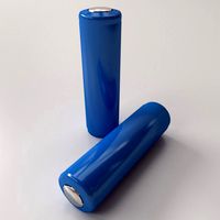
18650 Battery Frame by lewtwo
by Thingiverse
Last crawled date: 3 years, 1 month ago
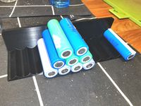
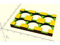
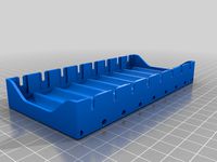
All this started out as a question that was posted on the EndlessSphere E-Bike forum regarding the practicality of printing modules on on a 3D printer that could be assembled together to form a battery frame for an 18650 battery pack. I tried a small hex unit for a single 18650 cell with dovetails and came to the conclusion that it was more trouble than it was worth. Thus I decided to try larger modules.
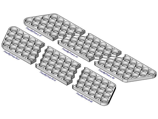
Most e-bike batteries are in the range of 36 to 60 volts which is 10 to 15 cells in series. They are also commonly 4 or 5 cells in parallel. The largest section size that I can print on my Creality Ender-2 is 5 by 5 and I have to lie to Cura a bit to accomplish that. The Ender-2 has a bit larger print bed than some other 3D printers in the same price and size range. Thus I decided to create the modules in both four and five parallel sections. A 36 volt battery only requires two FourByFive or FiveByFive sections to assemble a frame for each side of the battery pack. For more cells in series a center section is needed. Those of you that have the luxury of larger printbeds can join the sections in your slicer program to produce the frame as a single print.
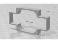
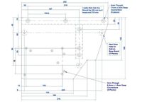
The parameters I used for the design were:
Height = 8.0 mm
Cell Hole Diameter = 18.60 mm
Cell Center to Center Distance = 20.00 mm
Mounting Hole Diameter = 3.0 mm
Mounting Hole Edge to Center Distance = 3.5 mm
Mounting Hole Center to Center Distance = 20, 40 or 60 mm
Chamfer Distance = 0.80 mm
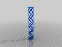
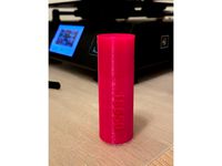
In order to determine the optimum cell hole diameter I designed and printed a gauge in ABS. I then test fit several cells into the gauge to determine the best fit. The size I chose was for a Samsung INR18650-25R that actually measures 18.30mm in diameter. There is some variance between the design size hole and the finished print. Some other cells such as UltraFire will be a bit sloppy.
As I chose to print these in ABS I had some problems with bed adhesion and warping. Thus I used a large brim and a generous amount of hair spray. To aid in cleanly removing the brim I incorporated 0.80 mm chamfers along the lower edges of the sections.
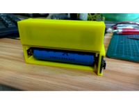
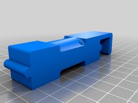
The Tabs and Sockets used to join the sections together are intended to be used during the process of solvent adhesive bonding of the sections. I do not believe that they provide adequate strength for an assembled battery pack on their own. I also encourage allowing sufficient time for the curing process. For bonding I recommend one of the following:
SCIGRIP #16 Acrylic Cement
IPS Weld-On #4 Acrylic Adhesive
IPS Weld-On #3 Acrylic Adhesive
Testors Model Comment #3509C
Methylene Chloride (99% pure)
Acetone (99% pure) … nail polish remover
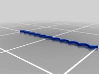
I used SCIGRIP for testing because it is what I happened to have on hand. I suspect that IPS Weld-On #3 would produce the best bond. I find that XXXByOne sections are a bit flimsy however they may be adequate in an assembled frame.
The 3mm holes along the sides were the last feature that I added after I discovered that one could acquire M3 Hex Socket head screws in 75 and 90 mm lengths. I find that I need to ream the small holes with a appropriate twist drill bit depending on if they are to be used as a clear through hole or threaded. There are other methods that can be used to secure the two sides but this alternative is provided because it was convenient to do so.
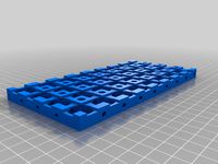
All the test prints were made using “Paramount 3D ABS (PANTONE Battleship Gray 431C) 1.75mm Filament” with a extrusion temperature of 225 degrees and a bed temperature of 100 degrees in 0.20mm layers. I also had the extrusion factor down to 0.95 to maintain detail for for the tabs and sockets. There was zero fill with 8 to 10 walls to produce a solid print.
Note that the left and right sides are opposite hand but the center sections (i.e. XXX-L-H and XXX-R-H) are interchangeable.
For those that have a CAD system capable correct loading a 3D DWG/DXF file with AICS solids I have also included the original CAD DXF files. All design work was done with BrisCAD 18.x running on a Linux Mint 18.3 operating system.
All of the referenced files are the exclusive work product of the author and placed into the Public Domain by the author 10 March 2018 without any warranty expressed or implied. --- Enjoy ---
Most e-bike batteries are in the range of 36 to 60 volts which is 10 to 15 cells in series. They are also commonly 4 or 5 cells in parallel. The largest section size that I can print on my Creality Ender-2 is 5 by 5 and I have to lie to Cura a bit to accomplish that. The Ender-2 has a bit larger print bed than some other 3D printers in the same price and size range. Thus I decided to create the modules in both four and five parallel sections. A 36 volt battery only requires two FourByFive or FiveByFive sections to assemble a frame for each side of the battery pack. For more cells in series a center section is needed. Those of you that have the luxury of larger printbeds can join the sections in your slicer program to produce the frame as a single print.
The parameters I used for the design were:
Height = 8.0 mm
Cell Hole Diameter = 18.60 mm
Cell Center to Center Distance = 20.00 mm
Mounting Hole Diameter = 3.0 mm
Mounting Hole Edge to Center Distance = 3.5 mm
Mounting Hole Center to Center Distance = 20, 40 or 60 mm
Chamfer Distance = 0.80 mm
In order to determine the optimum cell hole diameter I designed and printed a gauge in ABS. I then test fit several cells into the gauge to determine the best fit. The size I chose was for a Samsung INR18650-25R that actually measures 18.30mm in diameter. There is some variance between the design size hole and the finished print. Some other cells such as UltraFire will be a bit sloppy.
As I chose to print these in ABS I had some problems with bed adhesion and warping. Thus I used a large brim and a generous amount of hair spray. To aid in cleanly removing the brim I incorporated 0.80 mm chamfers along the lower edges of the sections.
The Tabs and Sockets used to join the sections together are intended to be used during the process of solvent adhesive bonding of the sections. I do not believe that they provide adequate strength for an assembled battery pack on their own. I also encourage allowing sufficient time for the curing process. For bonding I recommend one of the following:
SCIGRIP #16 Acrylic Cement
IPS Weld-On #4 Acrylic Adhesive
IPS Weld-On #3 Acrylic Adhesive
Testors Model Comment #3509C
Methylene Chloride (99% pure)
Acetone (99% pure) … nail polish remover
I used SCIGRIP for testing because it is what I happened to have on hand. I suspect that IPS Weld-On #3 would produce the best bond. I find that XXXByOne sections are a bit flimsy however they may be adequate in an assembled frame.
The 3mm holes along the sides were the last feature that I added after I discovered that one could acquire M3 Hex Socket head screws in 75 and 90 mm lengths. I find that I need to ream the small holes with a appropriate twist drill bit depending on if they are to be used as a clear through hole or threaded. There are other methods that can be used to secure the two sides but this alternative is provided because it was convenient to do so.
All the test prints were made using “Paramount 3D ABS (PANTONE Battleship Gray 431C) 1.75mm Filament” with a extrusion temperature of 225 degrees and a bed temperature of 100 degrees in 0.20mm layers. I also had the extrusion factor down to 0.95 to maintain detail for for the tabs and sockets. There was zero fill with 8 to 10 walls to produce a solid print.
Note that the left and right sides are opposite hand but the center sections (i.e. XXX-L-H and XXX-R-H) are interchangeable.
For those that have a CAD system capable correct loading a 3D DWG/DXF file with AICS solids I have also included the original CAD DXF files. All design work was done with BrisCAD 18.x running on a Linux Mint 18.3 operating system.
All of the referenced files are the exclusive work product of the author and placed into the Public Domain by the author 10 March 2018 without any warranty expressed or implied. --- Enjoy ---
Similar models
thingiverse
free
10x5 18650 Lithium Ion Battery Holder
... the batteries can be inserted and removed without forcing.
distance between each battery is 20mm.
infill from 5% to 20% is good.
thingiverse
free
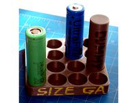
18650 Battery Size Gauge by lewtwo
...requires about eight hours on ender-2 printer.
update:
i needed bit more range so i created one with 16 holes from 18.00 to 18.75
thingiverse
free
18650 battery to 26650 adapter
...tery but i only do have 18650 batteries.
so it was easy job to print a rough adapter to get 18650 cell centered inside the light.
thingiverse
free
18650 jig for gluing battery packs
... the cells in place, add glue and then add the next layer with cells. after that its time to solder or spot weld then together :)
thingiverse
free
18650 Holder for Sparta Ion battery by Davideljeringa
...d 18650 battery cells on that pattern, this is particular pattern trying to copy the body frame of sparta ion battery body frame.
thingiverse
free
Double 26650 flashlight to 18650 battery bushing
...8650 batteries in a double 26650 flashlight. all it does is centering the smaller diameter batteries in a larger flashlight body.
thingiverse
free
18650 Detachable battery box by ARunningPanda
...18650 detachable battery box by arunningpanda
thingiverse
a simple trial of double-sided adhesive bonding.
thingiverse
free
Universal Battery Holder by Arcachofo
...epending on your printer settings you should add 0.1 to 0.5 mm.
there is an stl for 3s2p 18650 with 2 mm separation, 8 mm height.
thingiverse
free
18650 battery spacer - 2*10 slots by twentyone
....
for other numbers of cells in parallel, you can just print them out and snap them to length by hand since they are pretty thin.
thingiverse
free
18650 Battery Holder - 32 Cell
... 32 cell
thingiverse
18650 battery holder for a 4s8p battery pack i want to make. the small holes are intended for wire routing.
Lewtwo
thingiverse
free
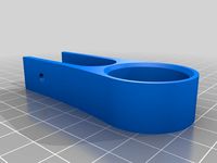
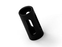
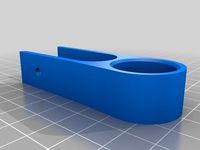
"Hanger" for 3/4 Conduit by lewtwo
... 3/4 conduit by lewtwo
thingiverse
simple hanger for 3/4 inch conduit. this is intended to hang the conduit under a 1 x ? board.
thingiverse
free
Hanger for 1/2 PVC Conduit by lewtwo
...onduit along the bottom edge of a 1x2. this should be a loose (not sloppy) fit as there is an extra 1/2mm on the inside diameter.
thingiverse
free
18650 Battery Size Gauge by lewtwo
...requires about eight hours on ender-2 printer.
update:
i needed bit more range so i created one with 16 holes from 18.00 to 18.75
thingiverse
free
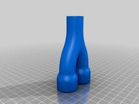
"Y" Split for 1/2 inch conduit by lewtwo
...extrusion factor.
this is a variation of my design for a “s” bend for 1/2 inch conduit: https://www.thingiverse.com/thing:2958303
thingiverse
free

"S" Bend for 1/2 inch conduit by lewtwo
...ps://www.thingiverse.com/thing:2959008
"y" split for 3/4 to 1/2 inch conduit: https://www.thingiverse.com/thing:2959940
thingiverse
free
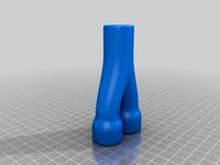
"Y" Split for 3/4 to 1/2 inch conduit by lewtwo
...extrusion factor.
this is a variation of my design for a “s” bend for 1/2 inch conduit: https://www.thingiverse.com/thing:2958303
thingiverse
free
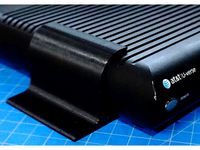
Wall Mount Bracket: At&T Set Top Box by lewtwo
...iles are the exclusive work product of the author, lewis balentine, who has placed them in the public domain on 17 february 2018.
thingiverse
free
Creality Ender-2 Base Plate by lewtwo
... the author and placed into the public domain by the author 5 april 2018 without any warranty expressed or implied. --- enjoy ---
thingiverse
free
Cooling Fan Shroud for Creality Ender-2 by lewtwo
...product of the author and placed into the public domain by the author 22 february 2018 without any warranty expressed or implied.
18650
3d_export
$10
battery 18650
...battery 18650
3dexport
battery 18650
turbosquid
$10
18650 Li-ion Battery
... available on turbo squid, the world's leading provider of digital 3d models for visualization, films, television, and games.
3d_export
$15
lithium ion 18650 battery
...e up render. - all parts and materials are logically named. other formats ================= - collada (.dae) - autodesk fbx - obj
3d_export
$10
18650 lithium battery
...your software before making a purchase is highly recommend. -in case of problems with the 3d model, do not hesitate to contact me
3d_export
free

solar rechargeable single led flashing light
...light 3dexport unit was design for housing a single 18650 lithium-ion battery and mini solar panel 55mm x 41mm-...
3d_export
$12

Emoji 042 Loudly Crying With Tears
...spec/gloss textures<br>- blend (cycles): metal/roughnes textures<br>geometry:<br>- units: centimeters<br>- polygons: 18650lt;br>- vertex: 18822<br>- triangles: 2<br>- quads: 18648<br>- ngons: 0<br>- vertex...
thingiverse
free
18650
...18650
thingiverse
18650 power supply, vase mode
thingiverse
free
18650 CASE
...18650 case
thingiverse
18650 case!
thingiverse
free
18650 holder
...18650 holder
thingiverse
18650 holder
thingiverse
free
18650 dispenser
...18650 dispenser
thingiverse
18650 dispenser for 10 batteries.
Battery
3d_ocean
$2
Battery
...battery
3docean
battery electronic
a high quality battery .
3d_export
free
battery
...battery
3dexport
battery
3d_ocean
$5
Battery
...battery
3docean
battery electronics
a classic 6 v battery, high poly with materials
3d_ocean
$3
Batteries
...batteries 3docean aa aaa batteries battery d electronics energy materials power subdivision uv unwrapped aa,...
3d_export
$19
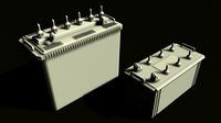
Lead-acid battery storage battery lithium battery
...ttery storage battery lithium battery
3dexport
1.lead-acid battery storage battery lithium battery 2.files include 3dmax obj fbx
3d_ocean
$7
Battery Model
...battery model
3docean
big battery car battery vehicle battery
car battery, big battery, vehicle battery.
3ddd
free
battery energier
...battery energier
3ddd
battery energier , батарейка
battery energier
turbosquid
free
battery
...battery
turbosquid
free 3d model battery for download as obj on turbosquid: 3d models for games, architecture, videos. (1151676)
3d_ocean
$1
Battery Model
...lack minus plus white yellow
this is battery model is about 1000 triangles. turntable preview is smoothed version of the battery.
3d_export
$10
battery 18650
...battery 18650
3dexport
battery 18650
Frame
archibase_planet
free
Frame
...frame
archibase planet
frame photo frame
frame n190813 - 3d model (*.gsm+*.3ds) for interior 3d visualization.
archibase_planet
free
Frame
...frame
archibase planet
frame photo frame
frame n071113 - 3d model (*.gsm+*.3ds) for interior 3d visualization.
3ddd
$1

Frame
...frame
3ddd
frame
3ddd
free
Frame
...frame
3ddd
frame
archibase_planet
free

Frame
...frame
archibase planet
frame mirror frame ornament
frame n260113 - 3d model (*.gsm+*.3ds) for interior 3d visualization.
archibase_planet
free

Frame
...frame
archibase planet
frame photo frame
frame photo n190813 - 3d model (*.gsm+*.3ds) for interior 3d visualization.
archibase_planet
free
Frame
...frame
archibase planet
frame window window frame
frame 1 - 3d model (*.gsm+*.3ds) for interior 3d visualization.
archibase_planet
free
Frame
...frame
archibase planet
frame window frame window
frame 3 - 3d model (*.gsm+*.3ds) for interior 3d visualization.
archibase_planet
free
Frame
...frame
archibase planet
frame wall frame decoration
frame 1 - 3d model (*.gsm+*.3ds) for interior 3d visualization.
archibase_planet
free
Frame
...frame
archibase planet
frame window window frame
frame 2 - 3d model (*.gsm+*.3ds) for interior 3d visualization.