Thingiverse
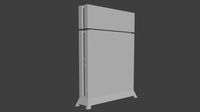
1-to-4 HDD Stackable Raspberry NAS with PSU v1 by fcerbell
by Thingiverse
Last crawled date: 3 years ago
It has serious cooling defects, do not print !
I'll release a new version later
Designer : Blender
Slicer : Slic3r
Printer : Creality 3D CR-10
Material : PLA Optimus 1.75 White (filament-abs.fr)
You should print the v2 instead : https://www.thingiverse.com/thing:2784565
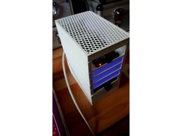
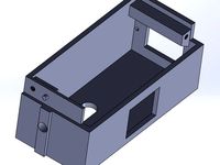
Compact Stackable Raspberry NAS with PSU and between 1 and 4 hotplug HDD
IMPORTANT
I made it, but I am not fully happy of it because of too much post-printing. I began a v2 with tradoffs on the HDD size and on the power rail.
The lower bullet connector holes are very tight and need heated to insert the terminals.
The bullet connectors are (too) hard to insert/remove from the stack
It does the job, but I'm not really happy with the ease of use/assembly. I'll probably make a v2.
Goal
A small NAS using a Raspberry, with 4 HDD and a power supply, to save energy and space. It does not have to be lightining fast for my home needs (backups, photos/movies/music repository, ...)
Design constraints
I currently use a small standard PC with 2x1TB HDD in RAID as a storage for backups with RSync. This is an overkill. I want to upgrade the usage with OpenMediaVault (http://www.openmediavault.org/) to store
my backups (RSync and/or Rsnapshot,
my movies (for XBMC/Kodi),
my music (for XBMC/Kodi),
a MacBook Air's timemachine backups.
I want to optimize the energy+space vs usage ration with :
Dedicated sized Power Suply Unit
Raspberry Pi 2 (no need for Wifi, Ethernet cable sharing the USB bus is fine)
4x 1TB HDD (SSD would be better, but far too expensive for this project and not justified)
I don't want to power the HDD from the RPi USB sockets, I chose to Double USB to SATA cable adaptor to get power directly from the PSU to the HDD
I don't want to power the RPi from its side USB power socket (bad location, power supposed clean, ... I'll power the RPi from the GPIO pins
I wont use any kind of UPS (in case of power failure, no client will connect) and it would be difficult to design such an UPS for the RPi and 4 spinning disks. I'll work at the software layer to make it robust against unexpected poweroff.
I want to be able to hotplug/unplug HDDs easily, without a tray
I want to be able to mout/unmount the stack to scale up/down using few screws and with backplane power rail connectors
I want to be able to insert/remove the RPi SD card without unmounting anything
The HDD bay needs to be able to receive different 2.5 HDD form factor (L=100mm, W=700mm H=9.5,12.5,17.19mm)
I still hate to remove and clean support material from my printings... The design should be supportless ! ;)
Bill Of Material :
Power cord
micro power switch 250V/3A : https://www.banggood.com/20pcs-250V-3A-Mini-Boat-Rocker-Switch-2-Pin-Plastic-Button-ONOff-SPST-p-1044250.html
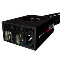
Generic Power Supply Unit AC 110-220V To DC 5V 6A 30W : https://www.banggood.com/AC-85-265V-to-DC-5V-6A-30W-Switch-Power-Supply-for-Car-LED-Strip-Lights-p-967013.html
Raspberry Pi 2
Raspberry Pi 2/3 Copper Heat Sink Heat Sink https://www.banggood.com/Raspberry-Pi-23-Copper-Heat-Sink-Heatsink-With-3M-Special-Thermal-Cooling-Paste-p-1045808.html
SD card
4x 1TB HDD : https://www.ldlc.com/fiche/PB00235600.html
4x Double USB to SATA cable adapter : https://www.banggood.com/Double-USB-2_0-Adapter-Cable-715pin-Male-to-Male-for-Laptop-2_5HDD-Hard-Disk-Drive-p-1026866.html
M3 6mm screws (the screws used in computers to secure all the parts together)
10 bullet connector pairs : https://www.banggood.com/Wholesale-10x-3_5mm-Gold-Bullet-Banana-Connector-Plug-For-ESC-Battery-Motor-p-51435.html?rmmds=search
Printing
Before printing
You might need :
to check and adjust the size and location of the screw holes for the PSU
to check and adjust the size and location of the screw holes and walls for the SATA-USB PCB adaptors depending on yours
to check and adjust the size of the bullet terminals (both length and width)
Even if you buy the same references from the same supplier, the item can change, sometimes. ;)
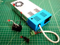
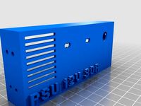
Power supply level (at the bottom for the stability):
Printed on CR-10, with PLA in 7 hours and 6 minutes (approx 66g of PLA)
Nozzle 0.4mm
first layer 0.375 mm @ 195°C/75°C, other layers: 0.2 mm @ 190°C/70°C
3 top layers, 3 bottom layers, 3 perimeters
Infill : 20% honeycomb
Skirt suggested, Brim recommended, no support
PSU mounted with 2xM3 screws
Added a mini-power switch
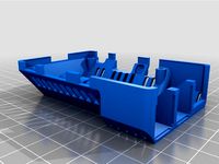
HDD level (between 1 and 4 times):
Printed on CR-10, with PLA in 3 hours and 53 minutes (approx. 51g of PLA)
Nozzle 0.4mm
first layer 0.375 mm @ 195°C/75°C, other layers: 0.2 mm @ 190°C/70°C
3 top layers, 3 bottom layers, 3 perimeters
Infill : 20% honeycomb
Skirt suggested, Brim recommended, no support
RPi level
Printed on CR-10, with PLA in 3 hours and few minutes
Nozzle 0.4mm
first layer 0.375 mm @ 195°C/75°C, other layers: 0.2 mm @ 190°C/70°C
3 top layers, 3 bottom layers, 3 perimeters
Infill : 20% honeycomb
Skirt suggested, Brim recommended, no support
Cover layer
Printed on CR-10, with PLA in 3 hours and 53 minutes (approx. 51g of PLA)
Nozzle 0.4mm
first layer 0.375 mm @ 195°C/75°C, other layers: 0.2 mm @ 190°C/70°C
0 top layers, 0 bottom layers, 5 perimeters
Infill : 20% honeycomb
Skirt suggested, Brim recommended, no support
Assembly
Power Supply
Pass the power cord through the front small hole, connect the negative to the N terminal on the PSU,
Pass the positive (brown or red) through the front switch hole (from inside to outside) and connect it to one of the switch terminals.
Connect the second switch terminal to the L terminal on the PSU (back through the switch hole) from outside to inside.
Solder a blue wire to one of the bullet, and a red wire to the other one.
Pass the blue wire from outside to insinde through the internal power stack hole and push the bullet in the hole (you can force or heat to make it pass, and use hot glue to secure it).
Pass the red wire from outside to insinde through the external power stack hole and push the bullet in the hole (you can force or heat to make it pass, and use hot glue to secure it).
Connect the blue wire to the negative terminal on the PSU and the red wire to the positive one.
Finally, use 2xM3 4mm sscrewws to secure the PSU on the bottom plate.
You can test that you don't have any shortcut with a volt metter.Connect a volt metter (set to more than 6V) to the bullets, the power cord to the main, and switch on the switch. The LED should light up.
Use a screw driver to adjust the voltage somewhere between 5 and 5.2V using the small tuning screw on the PSU, near the LED.
Hint: you can secure the bullet terminals in their holes using a piece of PLA/ABS from the skirt/brim/raft with your soldering/reworking station to lock the bullet in the hole.
HDD levels
Unmount the SATA plug adaptor (clipsed) to extract the PCB
solder a red wire on a male bullet
solder a red wire on a female bullet
solder a blue wire on a male bullet
solder a blue wire on a female bullet
pass the male red wire from outside to inside in the external bottom hole
pass the male blue wire from outside to inside in the internal bottom hole
add the male red wire to the female red bullet by soldering it
add the male blue wire to the female blue bullet by soldering it
push the female bullets in their hole, eventually securing them with hot glue or melted PLA/ABS
solder the red wire in place of the red wire (on one side) on the PCB
solder the blue wire in place of the black (on hte other side) wire on the PCB
secure and insulate as you want (cutting different length, using electric tape, using heat shrink tubes, ...) the red and black original wires
place the PCB on the tray with the SATA connector at the bottom and secure it with 2 M2 2/3/4mm screws
Hint : use your soldering iron tip to heat each of the bullets, one by one, to adjust their position and lock them in the ABS/PLA
Hint : Hotglue under the PCB to secure it more than with the 2 M2 screws only
Hint : Hot glue all around the bullet connectors
Hint : gently pre and post heat the hot glue with hot air (reworking station or air gun
RPI level
solder a red wire on a male bullet
solder a blue wire on a male bullet
pass the male red wire from outside to inside in the external bottom hole
pass the male blue wire from outside to inside in the internal bottom hole
crimp a dupont connector on the red wire
crimp a dupont connector on the blue wire
connect the red wire to the second pin and the blue wire to the third pin of the RPi GPIO (double check the pinout, you can frie your RPi)
Connect the USB plugs and the network.
Possible improvements:
Add status LED (Power)
Add status LED (System starting/started/stopping/stopped blink/loadHeartBeat/blinking/off)
Add status LED (OMV process stopped/starting/started no process=off, process but no http=blink, process and http=on)
Add an high voltage fuse
Add a graceful reboot/shutdown GPIO push button (short/long press)
Redesign the HDD level with a tray
I'll release a new version later
Designer : Blender
Slicer : Slic3r
Printer : Creality 3D CR-10
Material : PLA Optimus 1.75 White (filament-abs.fr)
You should print the v2 instead : https://www.thingiverse.com/thing:2784565
Compact Stackable Raspberry NAS with PSU and between 1 and 4 hotplug HDD
IMPORTANT
I made it, but I am not fully happy of it because of too much post-printing. I began a v2 with tradoffs on the HDD size and on the power rail.
The lower bullet connector holes are very tight and need heated to insert the terminals.
The bullet connectors are (too) hard to insert/remove from the stack
It does the job, but I'm not really happy with the ease of use/assembly. I'll probably make a v2.
Goal
A small NAS using a Raspberry, with 4 HDD and a power supply, to save energy and space. It does not have to be lightining fast for my home needs (backups, photos/movies/music repository, ...)
Design constraints
I currently use a small standard PC with 2x1TB HDD in RAID as a storage for backups with RSync. This is an overkill. I want to upgrade the usage with OpenMediaVault (http://www.openmediavault.org/) to store
my backups (RSync and/or Rsnapshot,
my movies (for XBMC/Kodi),
my music (for XBMC/Kodi),
a MacBook Air's timemachine backups.
I want to optimize the energy+space vs usage ration with :
Dedicated sized Power Suply Unit
Raspberry Pi 2 (no need for Wifi, Ethernet cable sharing the USB bus is fine)
4x 1TB HDD (SSD would be better, but far too expensive for this project and not justified)
I don't want to power the HDD from the RPi USB sockets, I chose to Double USB to SATA cable adaptor to get power directly from the PSU to the HDD
I don't want to power the RPi from its side USB power socket (bad location, power supposed clean, ... I'll power the RPi from the GPIO pins
I wont use any kind of UPS (in case of power failure, no client will connect) and it would be difficult to design such an UPS for the RPi and 4 spinning disks. I'll work at the software layer to make it robust against unexpected poweroff.
I want to be able to hotplug/unplug HDDs easily, without a tray
I want to be able to mout/unmount the stack to scale up/down using few screws and with backplane power rail connectors
I want to be able to insert/remove the RPi SD card without unmounting anything
The HDD bay needs to be able to receive different 2.5 HDD form factor (L=100mm, W=700mm H=9.5,12.5,17.19mm)
I still hate to remove and clean support material from my printings... The design should be supportless ! ;)
Bill Of Material :
Power cord
micro power switch 250V/3A : https://www.banggood.com/20pcs-250V-3A-Mini-Boat-Rocker-Switch-2-Pin-Plastic-Button-ONOff-SPST-p-1044250.html
Generic Power Supply Unit AC 110-220V To DC 5V 6A 30W : https://www.banggood.com/AC-85-265V-to-DC-5V-6A-30W-Switch-Power-Supply-for-Car-LED-Strip-Lights-p-967013.html
Raspberry Pi 2
Raspberry Pi 2/3 Copper Heat Sink Heat Sink https://www.banggood.com/Raspberry-Pi-23-Copper-Heat-Sink-Heatsink-With-3M-Special-Thermal-Cooling-Paste-p-1045808.html
SD card
4x 1TB HDD : https://www.ldlc.com/fiche/PB00235600.html
4x Double USB to SATA cable adapter : https://www.banggood.com/Double-USB-2_0-Adapter-Cable-715pin-Male-to-Male-for-Laptop-2_5HDD-Hard-Disk-Drive-p-1026866.html
M3 6mm screws (the screws used in computers to secure all the parts together)
10 bullet connector pairs : https://www.banggood.com/Wholesale-10x-3_5mm-Gold-Bullet-Banana-Connector-Plug-For-ESC-Battery-Motor-p-51435.html?rmmds=search
Printing
Before printing
You might need :
to check and adjust the size and location of the screw holes for the PSU
to check and adjust the size and location of the screw holes and walls for the SATA-USB PCB adaptors depending on yours
to check and adjust the size of the bullet terminals (both length and width)
Even if you buy the same references from the same supplier, the item can change, sometimes. ;)
Power supply level (at the bottom for the stability):
Printed on CR-10, with PLA in 7 hours and 6 minutes (approx 66g of PLA)
Nozzle 0.4mm
first layer 0.375 mm @ 195°C/75°C, other layers: 0.2 mm @ 190°C/70°C
3 top layers, 3 bottom layers, 3 perimeters
Infill : 20% honeycomb
Skirt suggested, Brim recommended, no support
PSU mounted with 2xM3 screws
Added a mini-power switch
HDD level (between 1 and 4 times):
Printed on CR-10, with PLA in 3 hours and 53 minutes (approx. 51g of PLA)
Nozzle 0.4mm
first layer 0.375 mm @ 195°C/75°C, other layers: 0.2 mm @ 190°C/70°C
3 top layers, 3 bottom layers, 3 perimeters
Infill : 20% honeycomb
Skirt suggested, Brim recommended, no support
RPi level
Printed on CR-10, with PLA in 3 hours and few minutes
Nozzle 0.4mm
first layer 0.375 mm @ 195°C/75°C, other layers: 0.2 mm @ 190°C/70°C
3 top layers, 3 bottom layers, 3 perimeters
Infill : 20% honeycomb
Skirt suggested, Brim recommended, no support
Cover layer
Printed on CR-10, with PLA in 3 hours and 53 minutes (approx. 51g of PLA)
Nozzle 0.4mm
first layer 0.375 mm @ 195°C/75°C, other layers: 0.2 mm @ 190°C/70°C
0 top layers, 0 bottom layers, 5 perimeters
Infill : 20% honeycomb
Skirt suggested, Brim recommended, no support
Assembly
Power Supply
Pass the power cord through the front small hole, connect the negative to the N terminal on the PSU,
Pass the positive (brown or red) through the front switch hole (from inside to outside) and connect it to one of the switch terminals.
Connect the second switch terminal to the L terminal on the PSU (back through the switch hole) from outside to inside.
Solder a blue wire to one of the bullet, and a red wire to the other one.
Pass the blue wire from outside to insinde through the internal power stack hole and push the bullet in the hole (you can force or heat to make it pass, and use hot glue to secure it).
Pass the red wire from outside to insinde through the external power stack hole and push the bullet in the hole (you can force or heat to make it pass, and use hot glue to secure it).
Connect the blue wire to the negative terminal on the PSU and the red wire to the positive one.
Finally, use 2xM3 4mm sscrewws to secure the PSU on the bottom plate.
You can test that you don't have any shortcut with a volt metter.Connect a volt metter (set to more than 6V) to the bullets, the power cord to the main, and switch on the switch. The LED should light up.
Use a screw driver to adjust the voltage somewhere between 5 and 5.2V using the small tuning screw on the PSU, near the LED.
Hint: you can secure the bullet terminals in their holes using a piece of PLA/ABS from the skirt/brim/raft with your soldering/reworking station to lock the bullet in the hole.
HDD levels
Unmount the SATA plug adaptor (clipsed) to extract the PCB
solder a red wire on a male bullet
solder a red wire on a female bullet
solder a blue wire on a male bullet
solder a blue wire on a female bullet
pass the male red wire from outside to inside in the external bottom hole
pass the male blue wire from outside to inside in the internal bottom hole
add the male red wire to the female red bullet by soldering it
add the male blue wire to the female blue bullet by soldering it
push the female bullets in their hole, eventually securing them with hot glue or melted PLA/ABS
solder the red wire in place of the red wire (on one side) on the PCB
solder the blue wire in place of the black (on hte other side) wire on the PCB
secure and insulate as you want (cutting different length, using electric tape, using heat shrink tubes, ...) the red and black original wires
place the PCB on the tray with the SATA connector at the bottom and secure it with 2 M2 2/3/4mm screws
Hint : use your soldering iron tip to heat each of the bullets, one by one, to adjust their position and lock them in the ABS/PLA
Hint : Hotglue under the PCB to secure it more than with the 2 M2 screws only
Hint : Hot glue all around the bullet connectors
Hint : gently pre and post heat the hot glue with hot air (reworking station or air gun
RPI level
solder a red wire on a male bullet
solder a blue wire on a male bullet
pass the male red wire from outside to inside in the external bottom hole
pass the male blue wire from outside to inside in the internal bottom hole
crimp a dupont connector on the red wire
crimp a dupont connector on the blue wire
connect the red wire to the second pin and the blue wire to the third pin of the RPi GPIO (double check the pinout, you can frie your RPi)
Connect the USB plugs and the network.
Possible improvements:
Add status LED (Power)
Add status LED (System starting/started/stopping/stopped blink/loadHeartBeat/blinking/off)
Add status LED (OMV process stopped/starting/started no process=off, process but no http=blink, process and http=on)
Add an high voltage fuse
Add a graceful reboot/shutdown GPIO push button (short/long press)
Redesign the HDD level with a tray
Similar models
thingiverse
free

1-to-4 HDD Stackable Raspberry NAS with PSU v2 by fcerbell
...a pcb with screws, not only hot glue (will probably melt after several hours)
i wont work on it until some time, so, i release it
thingiverse
free

2020 mount for flyingbear P902 PSU with switch and banana sockets by BETLOG
...www.aliexpress.com/item/new-high-quality-red-light-power-rocker-switch-fused-iec-320-c14-inlet-power-socket-fuse/32720278625.html
thingiverse
free

Scalar - 200W Power supply box by 3DModularSystems
...ww.3dmodularsystems.com
twitter: https://twitter.com/3dmodularsystem
youtube: http://www.youtube.com/c/3dmodularsystems3dprinters
thingiverse
free

4mm banana plug bullet connector male right angle cover by mc1457
...covers. you may need to tap them in gently.
print negative in black, positive in red. pla or abs is fine. fits a 3mm wire snugly.
thingiverse
free

Bus Terminal with switches by Jahmez
...blocking the mounting holes.
the screw holes are all 3mm
the switch: http://www.ebay.com/itm/201514135585
size: 21 15 18.1 (mm)
thingiverse
free

Spade Connector Distribution Block by frankjay
...s version of the design but i'm confident it is the best one so far
i will have photos of the assembly steps uploaded shortly
thingiverse
free

Dual PSU brackets and wiring cover by ian_in_the_midlands
...ses and led indicators.
when fitted in place the cover encloses all of the wiring, and also blocks access to the screw terminals.
thingiverse
free
Power Supply Cover by thehans
...ply terminals.
works great in conjunction with my psu bracket for 2020 aluminum extrusionhttp://www.thingiverse.com/thing:1091724
thingiverse
free

Ender 3 PSU cover by sworfisc
... for switches, connector may be attached using m3 threaded inserts, on the back it has a hole to pass throught the xt60 connector
thingiverse
free

HP DPS-600 Power supply cable passthrough by RsX
...r and soldered the wires directly onto the pcb.
this is a nice cover to close the big connector hole and pass through the cables.
Fcerbell
thingiverse
free

Triple bench power supply with Ruideng DPS5020 and DPS5015 by fcerbell
...anana inlets
awg16 and awg20 wires
39 x m3x12mm screws
12 x m2x9mm screws
3 x 3 positions (on-off-on, 3 pins switch
1 x powercord
thingiverse
free

AC/DC 24V 2A adapter holder / mount by fcerbell
...=myorder&cur_warehouse=cn) that came without mounting holes. it has to be mounted on wood (below the roof)
printed in 4 hours
thingiverse
free

Home automation center by fcerbell
...ally, the server includes the core (power supply, ups, raspberry and zwave shield, everthing else is optional (rfx and mysensors)
thingiverse
free

Customizable multi wrapping wire dispenser by fcerbell
...e improvements
a handle that could host a sponge or foam to pin the wires
row aligned fillers to strengthen the fillers and sides
thingiverse
free
1-to-4 HDD Stackable Raspberry NAS with PSU v2 by fcerbell
...a pcb with screws, not only hot glue (will probably melt after several hours)
i wont work on it until some time, so, i release it
thingiverse
free

Wireless MySensors solar weather and pool monitoring by fcerbell
...ter flow
motorized water valves to automate the water flow management through the solar heating carpet and the electrical heating
Hdd
turbosquid
$20

HDD
... available on turbo squid, the world's leading provider of digital 3d models for visualization, films, television, and games.
turbosquid
$5

HDD Rack
...urbosquid
royalty free 3d model hdd rack for download as skp on turbosquid: 3d models for games, architecture, videos. (1289401)
turbosquid
$1
External HDD
...squid
royalty free 3d model external hdd for download as c4d on turbosquid: 3d models for games, architecture, videos. (1250314)
turbosquid
$10
Extern HDD
... available on turbo squid, the world's leading provider of digital 3d models for visualization, films, television, and games.
3d_export
$6

hdd sata wd10ezex 1tb
...hdd sata wd10ezex 1tb
3dexport
wd hdd sata disk model.
3ddd
free

HDD Transcend 320Gb
... transcend , жесткий диск
внешний жесткий диск transcend
без текстур
формат 3dmax, 3ds
3d_export
$10

External HDD 3D Model
...xport
hard disk drive external seagate usb storage hdd portable expansion data mobile
external hdd 3d model nkfrds 47740 3dexport
turbosquid
$5

HDD Rack Horizontal
...royalty free 3d model hdd rack horizontal for download as skp on turbosquid: 3d models for games, architecture, videos. (1289399)
turbosquid
$49

HDD Quantum Fireball
...l hdd quantum fireball for download as max, obj, 3ds, and fbx on turbosquid: 3d models for games, architecture, videos. (1630260)
3d_ocean
$10

Seagate External Hdd
... modeled in rhino4 3d and rendered with vray available formats:.3dm, .max(2011), .c4d(r12), .3ds, .obj textures:included mater...
Psu
3d_ocean
$17
Computer Case
...3docean atx case computer corsair full game gaming pc psu full tower-like computer case model with 113946...
cg_studio
$9
Power Supply Unit PSU3d model
...d .fbx .lwo .ma .max .obj .xsi - power supply unit psu 3d model, royalty free license available, instant download after purchase.
thingiverse
free
PSU cover for 12v 30A PSU by Salti
...
cover for the "dangerous" end of a standard led psu
230v input, 2 x 12v outputs
supports psu width 11cm and height 5cm
thingiverse
free

psu holder by sta8atos
...psu holder by sta8atos
thingiverse
psu holder
thingiverse
free
psu stamp by astorck
...psu stamp by astorck
thingiverse
psu stamp
thingiverse
free

PSU Cover by Shojo
...psu cover by shojo
thingiverse
psu cover
thingiverse
free
PSU cover by chroja
...psu cover by chroja
thingiverse
psu cover
thingiverse
free

PSU Cover for 9,9 cm PSU Anet A8 by Wolverine_DH
...a8 by wolverine_dh
thingiverse
psu cover for 9.9sm psu optimal high for anet a8 screw holes, more side holes for diffrend psus.
thingiverse
free

Anet A8 PSU Fan (2017 PSU)
...coarse threaded fan screws. additionally 2 x m3x8mm machine screws needed to attach fan mount to psu. do not use long than 8mm.
thingiverse
free

SFX PSU to ATX PSU adapter by Kanashii
... atx format adapter so i made my own adapter. better use hard plastic to stick psu to pc's case without breaking the adapter.
Stackable
turbosquid
$19

Stackable Furniture
...ty free 3d model stackable furniture for download as and iam on turbosquid: 3d models for games, architecture, videos. (1464888)
turbosquid
$15

Stackable Chair
... available on turbo squid, the world's leading provider of digital 3d models for visualization, films, television, and games.
3ddd
$1

ROMOLA STACKABLE CAFE/DINING
...ackable cafe/dining , cosmorelax
стул romola stackable cafe/dining /max2011,fbx,obj,mat/
3d_ocean
$6

Olivia Stackable Chair
... the olivia chair, designed by raul barbieri, featuring its perfect circle back. in polypropylene and chrome. seat height – 0....
turbosquid
$6

Sila Chair Stackable
...l sila chair stackable for download as mat, max, obj, and fbx on turbosquid: 3d models for games, architecture, videos. (1219891)
turbosquid
$2

Escher Stackable Table
...escher stackable table for download as 3ds, max, obj, and fbx on turbosquid: 3d models for games, architecture, videos. (1305530)
turbosquid
$24

Lily Upholstered Stackable
... available on turbo squid, the world's leading provider of digital 3d models for visualization, films, television, and games.
turbosquid
$14

Stackable ottoman model
... available on turbo squid, the world's leading provider of digital 3d models for visualization, films, television, and games.
turbosquid
$12

On stage Cantilever stackable
... available on turbo squid, the world's leading provider of digital 3d models for visualization, films, television, and games.
turbosquid
$12

Armchair stackable Capri
... available on turbo squid, the world's leading provider of digital 3d models for visualization, films, television, and games.
Raspberry
3d_export
free

raspberry
...raspberry
3dexport
3d model of a raspberry. i tried to make it realistic.
turbosquid
$27
Raspberries
...y free 3d model raspberries for download as max, obj, and stl on turbosquid: 3d models for games, architecture, videos. (1354176)
turbosquid
$14

Raspberries
...y free 3d model raspberries for download as max, obj, and fbx on turbosquid: 3d models for games, architecture, videos. (1364663)
3d_export
$5
raspberry pi
...raspberry pi
3dexport
carcasa para la raspberry pi
turbosquid
$99

Raspberry
... available on turbo squid, the world's leading provider of digital 3d models for visualization, films, television, and games.
turbosquid
$10

raspberries
... available on turbo squid, the world's leading provider of digital 3d models for visualization, films, television, and games.
archive3d
free

Raspberries 3D Model
...raspberries 3d model archive3d raspberries raspberry raspberries n300911 - 3d model (*.3ds) for interior 3d...
3d_export
$5

raspberry fruit
...raspberry fruit
3dexport
3d_export
$5

raspberry
...y different sizes. their color ranges from light burgundy to pink. there are formats: obj, 3ds, blend, dae, fbx, mtl.<br>:)
evermotion
$12

raspberries 23 am130
...evermotion raspberries 23 am130 evermotion key 23 food fruit raspberry fruits am130 raspberries highly detailed 3d model of raspberries...
V1
turbosquid
$35

v1
... available on turbo squid, the world's leading provider of digital 3d models for visualization, films, television, and games.
3d_export
$10

street tree v1
...street tree v1
3dexport
street tree v1
3d_export
$5

potato v1
...potato v1
3dexport
turbosquid
$20

Kitchen V1
...bosquid
royalty free 3d model kitchen v1 for download as max on turbosquid: 3d models for games, architecture, videos. (1153622)
turbosquid
$12

sofa v1
...turbosquid
royalty free 3d model sofa v1 for download as max on turbosquid: 3d models for games, architecture, videos. (1283267)
turbosquid
$3

Chair V1
...urbosquid
royalty free 3d model chair v1 for download as fbx on turbosquid: 3d models for games, architecture, videos. (1486093)
turbosquid
$15

Cupboard v1
...royalty free 3d model cupboard v1 for download as max and fbx on turbosquid: 3d models for games, architecture, videos. (1444568)
3d_export
$5

tram v1
...tram v1
3dexport
3d_export
$8

lumber car v1
...lumber car v1
3dexport
lumber car v1 printable, low poly model.
turbosquid
$20

DELTALIGHT v1
...free 3d model deltalight v1 for download as max, max, and obj on turbosquid: 3d models for games, architecture, videos. (1630928)
Nas
design_connected
$13

Na Xemena lounger
...na xemena lounger
designconnected
gandia blasco na xemena lounger computer generated 3d model. designed by gandia-blasco, jose.
3d_export
$15

nas storage
...e up render. - all parts and materials are logically named. other formats ================= - collada (.dae) - autodesk fbx - obj
turbosquid
$20

Table dr Na
... available on turbo squid, the world's leading provider of digital 3d models for visualization, films, television, and games.
turbosquid
free

RAID NAS 4TB
... available on turbo squid, the world's leading provider of digital 3d models for visualization, films, television, and games.
3ddd
$1

Aromas NA 777
...dd
aromas
люстра aromas na 777
1500mm x 200mm x 1140mmhttp://www.aromasdelcampo.com/ficha.php?f=4&t;=2&id;=130
design_connected
$18

New Antiques NA/1CB
... antiques na/1cb
designconnected
cappellini new antiques na/1cb chairs computer generated 3d model. designed by marcel wanders.
3ddd
$1

QNAP NAS Server
...qnap nas server
3ddd
сервер
сервер, сетевой накопитель.
polys/verts 41711/51066
turbosquid
$25

CIWL Boxcar NA 1259
...d model ciwl boxcar na 1259 for download as obj, c4d, and fbx on turbosquid: 3d models for games, architecture, videos. (1470438)
turbosquid
$9

Chandra rugs NAS-13702
... available on turbo squid, the world's leading provider of digital 3d models for visualization, films, television, and games.
turbosquid
$9

Chandra rugs NAS-13701
... available on turbo squid, the world's leading provider of digital 3d models for visualization, films, television, and games.
4
turbosquid
$9

Office Chair 4-4
... available on turbo squid, the world's leading provider of digital 3d models for visualization, films, television, and games.
3d_export
$5

doors- 4
...doors- 4
3dexport
doors 4
3d_export
$5
hinge 4
...hinge 4
3dexport
hinge 4
3ddd
$1

Штора №4
...штора №4
3ddd
штора №4
3d_export
free
playstation 4
...playstation 4
3dexport
playstation 4
turbosquid
$1

re 4-4 electric locomotive
... free 3d model re 4 4 electric locomotive for download as obj on turbosquid: 3d models for games, architecture, videos. (1707845)
3ddd
$1

nexus 4
...nexus 4
3ddd
lg , телефон
nexus 4
3ddd
$1
4 Poufs
...4 poufs
3ddd
пуф
4 soft poufs
turbosquid
$12

Calligraphic Digit 4 Number 4
...hic digit 4 number 4 for download as max, obj, fbx, and blend on turbosquid: 3d models for games, architecture, videos. (1389332)
3ddd
$1
Dauphin 4+
...dauphin 4+
3ddd
кресло
dauphin 4+ конференц кресло
1
turbosquid
$69

armchairs(1)(1)
... available on turbo squid, the world's leading provider of digital 3d models for visualization, films, television, and games.
turbosquid
$15

ring 1+1
... available on turbo squid, the world's leading provider of digital 3d models for visualization, films, television, and games.
turbosquid
$10
chair(1)(1)
... available on turbo squid, the world's leading provider of digital 3d models for visualization, films, television, and games.
turbosquid
$8

Chair(1)(1)
... available on turbo squid, the world's leading provider of digital 3d models for visualization, films, television, and games.
turbosquid
$2

RING 1(1)
... available on turbo squid, the world's leading provider of digital 3d models for visualization, films, television, and games.
turbosquid
$1
house 1(1)
... available on turbo squid, the world's leading provider of digital 3d models for visualization, films, television, and games.
turbosquid
$1
Table 1(1)
... available on turbo squid, the world's leading provider of digital 3d models for visualization, films, television, and games.
turbosquid
$59

Formula 1(1)
...lty free 3d model formula 1 for download as max, fbx, and obj on turbosquid: 3d models for games, architecture, videos. (1567088)
design_connected
$11
No 1
...no 1
designconnected
sibast no 1 computer generated 3d model. designed by sibast, helge.
turbosquid
$2
desert house(1)(1)
...3d model desert house(1)(1) for download as 3ds, max, and obj on turbosquid: 3d models for games, architecture, videos. (1055095)