Thingiverse

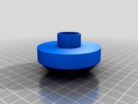
Zentrierständer für Fahrrad-Laufräder / bicycle wheel truing stand by Hardy
by Thingiverse
Last crawled date: 3 years, 1 month ago
GENERAL
This is a centering-stand for bicycles (https://youtu.be/lWbWG2VxNOA). Good ones are very expensive and I thought to help me and others by building one on my own. I'm using the self-centering gears from Catarina Mota (Helical Gears / https://www.thingiverse.com/thing:1339). Feel free to improve the Design: https://github.com/VirToReal/Centering-Stand-for-Bicycle/
Its fully customizable with the help of parameters in OpenSCAD. The Thingiverse-Customizer wont work here, because the "gears_helical.scad" must be in the same directory of the "Zentrierstaender.scad". Simply download them or clone from the Git-Hub Link.
CONSTRUCTING
Add the Parameters to fit the size of your wheel. You can be clumsy with that,
because the turquoise colored rods in the OpenScad-Preview are threaded-rods
and can be easily adjusted to your needed distances. Because of that, better
give some more than having to less at the end.
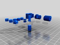
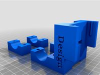
The variable "printmode" help you switch between OpenSCAD-Preview and Printmode.
The Preview shows your Adjustments on the Parameters. The "printmode = true" with
it's following variables will prepare a print-ready layout of your parametered
Structures. The length of each (not printable) Threaded-Rod will be "echoed" in the
OpenSCAD-Console. They can be cut in exact that length.
Following things have to be considered while building:
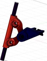
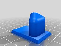
RIM-GRABBER:
All other small holes can be drilled up to 4mm for 20mm long M4 Screws to
assemble the whole Rim-Grabber altogether.
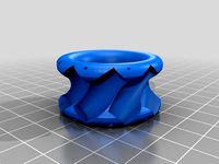
You have to pull a shell with the length of 10.15mm inside the two gears
The Diameter of the shell should match the size of appr. 5-5.9mm, it doesn't
have to be exact that size, tolerance to the Hole in the Gear is desirable.
You have to drill up the Hole in the Gears up to appr. 6mm too, because your
printer won't work that exactly. For Example: I used 2x 3mm² end sleeves which
fits perfectly.
There must fit a 3mm Screw inside that shell to fix these two gears together
with fewer tolerances. Be sure the screws just fix the shell with the other
two structures (cap/baseplate), not the gears! Some grease will help, too!
The two arms of the Grabber should touch in the center before mounting.
You can rotate them altogether to fix them afterwards. Just be sure they're
in the right teeth of the gear. ITS IMPORTANT THAT THESE GEARS HAVE NO
TOLERANCES TO EACH OTHER.
The two big holes are for the Threaded Rods. They're also fixing the "cap"
on the "baseplate" with the Gears between them.
Cut a thread into the two Grabber-Arms for M5-Screws and place some inside
them. They should look out the structure the same distance. If you failed
with assembling the Grabber-Arms correctly, you can adjust here.
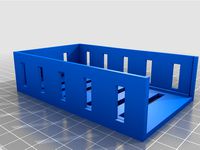
ALL OTHER PARTS:
Not much to consider, just use Nut-Traps if there are one. Washers may prevent
the plastic from damage. Locknuts on some points may help against self adjusting.
The OpenSCAD Preview with "printmode = false" may explain everything to you.
USING
Consider following things before start working with this tool:
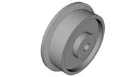
Be sure to tighten the Axis by clamping them in with the two Impeller-Holder.
You have to measure in your Rim first before start working on it. You're able
to rearrange the "Rim-Grabber" on the Threaded Rod for this.
If all Threaded Rods are tightened, the whole Structures may move during work
on your rim, but they'll always move back in they're original position. The
position will stay the same even after reinserting the rim after removal.
You'll detect the wrong position by the sound when the rim touches one of the screws.
Measuring right at the Rim-Grabber makes it easy to adjust the spokelength. Always Adjust 3 spokes before/after the one with the strongest swing to get a smoother result.
You're also be able to add a metal-plate to detect runouts of the rim. Just use the
upper two screws of the Rim-Grabber to mount one.
This is a centering-stand for bicycles (https://youtu.be/lWbWG2VxNOA). Good ones are very expensive and I thought to help me and others by building one on my own. I'm using the self-centering gears from Catarina Mota (Helical Gears / https://www.thingiverse.com/thing:1339). Feel free to improve the Design: https://github.com/VirToReal/Centering-Stand-for-Bicycle/
Its fully customizable with the help of parameters in OpenSCAD. The Thingiverse-Customizer wont work here, because the "gears_helical.scad" must be in the same directory of the "Zentrierstaender.scad". Simply download them or clone from the Git-Hub Link.
CONSTRUCTING
Add the Parameters to fit the size of your wheel. You can be clumsy with that,
because the turquoise colored rods in the OpenScad-Preview are threaded-rods
and can be easily adjusted to your needed distances. Because of that, better
give some more than having to less at the end.
The variable "printmode" help you switch between OpenSCAD-Preview and Printmode.
The Preview shows your Adjustments on the Parameters. The "printmode = true" with
it's following variables will prepare a print-ready layout of your parametered
Structures. The length of each (not printable) Threaded-Rod will be "echoed" in the
OpenSCAD-Console. They can be cut in exact that length.
Following things have to be considered while building:
RIM-GRABBER:
All other small holes can be drilled up to 4mm for 20mm long M4 Screws to
assemble the whole Rim-Grabber altogether.
You have to pull a shell with the length of 10.15mm inside the two gears
The Diameter of the shell should match the size of appr. 5-5.9mm, it doesn't
have to be exact that size, tolerance to the Hole in the Gear is desirable.
You have to drill up the Hole in the Gears up to appr. 6mm too, because your
printer won't work that exactly. For Example: I used 2x 3mm² end sleeves which
fits perfectly.
There must fit a 3mm Screw inside that shell to fix these two gears together
with fewer tolerances. Be sure the screws just fix the shell with the other
two structures (cap/baseplate), not the gears! Some grease will help, too!
The two arms of the Grabber should touch in the center before mounting.
You can rotate them altogether to fix them afterwards. Just be sure they're
in the right teeth of the gear. ITS IMPORTANT THAT THESE GEARS HAVE NO
TOLERANCES TO EACH OTHER.
The two big holes are for the Threaded Rods. They're also fixing the "cap"
on the "baseplate" with the Gears between them.
Cut a thread into the two Grabber-Arms for M5-Screws and place some inside
them. They should look out the structure the same distance. If you failed
with assembling the Grabber-Arms correctly, you can adjust here.
ALL OTHER PARTS:
Not much to consider, just use Nut-Traps if there are one. Washers may prevent
the plastic from damage. Locknuts on some points may help against self adjusting.
The OpenSCAD Preview with "printmode = false" may explain everything to you.
USING
Consider following things before start working with this tool:
Be sure to tighten the Axis by clamping them in with the two Impeller-Holder.
You have to measure in your Rim first before start working on it. You're able
to rearrange the "Rim-Grabber" on the Threaded Rod for this.
If all Threaded Rods are tightened, the whole Structures may move during work
on your rim, but they'll always move back in they're original position. The
position will stay the same even after reinserting the rim after removal.
You'll detect the wrong position by the sound when the rim touches one of the screws.
Measuring right at the Rim-Grabber makes it easy to adjust the spokelength. Always Adjust 3 spokes before/after the one with the strongest swing to get a smoother result.
You're also be able to add a metal-plate to detect runouts of the rim. Just use the
upper two screws of the Rim-Grabber to mount one.
Similar models
thingiverse
free
44mm Mecanum Wheel for 3mm D-shaft by tomatpasser
...s which have a tolerance of 6%. you can use the file shaft_test.scad to try different tolerances before printing the whole wheel.
thingiverse
free

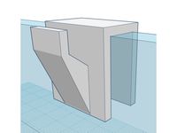
M8 Rod Floor-mount holder for Prusa i3 by Killer_Angel
...
this detail help you to mount your prusa i3 to the "floor"
this detail is made for m8 threaded rods
make in openscad
thingiverse
free

Dremel 4000 Adjustable Stand Holder by bkeeber2011
...39;re done, slowly remove the two nuts from the screw. as they come off, they'll re-align the screw threads at the cut-point.
thingiverse
free

Wheel (Tire, Rim with M6 thread) by CreoMan
...has a m6 thread. you can use a threaded rod for the axle. it fixes the two parts together and it is very stable at the same time!
thingiverse
free

The Brass Grabber by Ken73
...come back and fix the spring orientation (but it works for now) as well as put in some recesses for flat-head m3 screws and nuts.
thingiverse
free

APS M870 Shell Toolkit by Mdigibou
...irst just to make sure your dimensions are correct and you're holding a good seal. also safer than co2 or higher than 800psi.
thingiverse
free
OpenScad Helix for custom 2D profile and many thread types by zuiopl
...s needed.
update 23.04.2017 : removed "debug feature" which created incorrect threads for small diameters (around 3mm).
thingiverse
free
Battery Holder by justheath
...d is dad approved!
attribution
openscad screw holes by carloverse is licensed under creative commons - share alike - attribution.
grabcad
free

Generic metric threaded rod
...m)
more information on iso metric threading parameters can be found here :
http://en.wikipedia.org/wiki/iso_metric_screw_thread
thingiverse
free

Tapered Threaded Rod (bolt) module for openSCAD by wambold
...le, as are the rod length and hexagon head dimensions.
if you have comments, please send them to ascendiac@gmail.com .
thanks!
-w
Zentrierständer

Laufräder
grabcad
free

Caster wheel ø 200 PE
...caster wheel ø 200 pe grabcad laufräder ø 200 pe feste und...
3dwarehouse
free

Laufräder aus Stahl
...d #maedler #megacad #one_space_designer #online_3d_part_library #partsolutions #proe_wildfire #solidedge #solidworks #unigraphics
3dwarehouse
free

Laufräder aus Polyamid mit einseitigem Spurkranz
...d #maedler #megacad #one_space_designer #online_3d_part_library #partsolutions #proe_wildfire #solidedge #solidworks #unigraphics
3dwarehouse
free

Laufräder 712 AV, Ausführung mit Gleitlager
...d #maedler #megacad #one_space_designer #online_3d_part_library #partsolutions #proe_wildfire #solidedge #solidworks #unigraphics
3dwarehouse
free
Laufräder 712 AV, Ausführung mit Kugellager
...d #maedler #megacad #one_space_designer #online_3d_part_library #partsolutions #proe_wildfire #solidedge #solidworks #unigraphics
Fahrrad
thingiverse
free

Fahrrad-Trinkflaschenhalter by GDias
...fahrrad-trinkflaschenhalter by gdias
thingiverse
fahrrad-trinkflaschenhalter für flaschen mit einem durchmesser von etwa 76 mm.
thingiverse
free
Fahrrad - Ruecklichthalter by Krueml8476
...fahrrad - ruecklichthalter by krueml8476
thingiverse
fahrradhalter
thingiverse
free

Fahrrad Ritzelblatt Werkzeug by IrAl_KbK
...verse
werkzeug um die verschraubung des ritzels am hinterrad des fahrrads zu schrauben.
23,5mm x 23,5mm x 20mm
abs - 100% infill
thingiverse
free

Fahrrad Bremsleitungsbefestigung / Bicycle Brake Cable Clip by CBiker
...fahrrad bremsleitungsbefestigung / bicycle brake cable clip by cbiker
thingiverse
fahrrad bremsleitungsbefestigung
thingiverse
free

Fahrrad Flaschenhalter by The-Holgi
...y the-holgi
thingiverse
flaschenhalter für 1 liter pet mineralwasserflaschen.
passt an die standarthaltepunkte am fahrradrahmen.
thingiverse
free
Fahrrad Halter Baofeng UV5R by dirtdevil38
...devil38
thingiverse
baofeng uv 5r fahrrad halterung für lenker mit 25mm durchmesser.
material petg oder pla+ bzw. abs benutzen!
thingiverse
free

Fahrrad Kettenschloss Oeffner V2 / Bicycle Chainlink Opener Tool by CBiker
...loss oeffner v2 / bicycle chainlink opener tool by cbiker
thingiverse
fahrrad kettenschloss oeffner (neue flexiblere version v2)
thingiverse
free

Handknauf fuer Powerfix Fahrrad-Montagestaender / Clamping Knob by CBiker
...hingiverse
handknauf zum leichten verstellen der klemmbacken
passend für powerfix fahrrad-montagestaender
mit m10 fluegelmutter.
thingiverse
free

Fahrrad Schalt- und Bremszug Endhuelsen / Bicycle Shift- and Brakecable Sleeve by CBiker
...ift- and brakecable sleeve by cbiker
thingiverse
endhuelsen fuer fahrrad schalt- und bremszuege.
1,2mm und 1,6mm zugdurchmesser.
thingiverse
free

Fahrrad Radsender Befestigung / Bicycle Speedsensor Mount by CBiker
...fahrrad radsender befestigung / bicycle speedsensor mount by cbiker
thingiverse
ersetzt befestigung mit kabelbindern
Truing
turbosquid
free

TRU-BA P / BOSMA
... available on turbo squid, the world's leading provider of digital 3d models for visualization, films, television, and games.
turbosquid
$3

motorcycle crank shaft truing stand
... model motorcycle crank shaft truing stand for download as ma on turbosquid: 3d models for games, architecture, videos. (1273987)
turbosquid
free

TRU-BA vertical P / BOSMA
... available on turbo squid, the world's leading provider of digital 3d models for visualization, films, television, and games.
turbosquid
free

TRU-BA vertical F / BOSMA
... available on turbo squid, the world's leading provider of digital 3d models for visualization, films, television, and games.
3ddd
free
2 Dining Table + Trus Coffee Table
...n the u.s.a.; circa 1960'shttp://www.ltwid.com/vintage-charles-hollis-jones-post-trus-coffee-table-pid-1_8_3151.php
cg_studio
$19
Classic Wire Wheel & Tire BFG3d model
...tic
.obj .fbx .max - classic wire wheel & tire bfg 3d model, royalty free license available, instant download after purchase.
3d_export
$20

Brain of a Human 3D Model
...n aju utak aivot cerveau cerebro hersenen smegenys mozog beyin agy cervello
brain of a human 3d model 5starsmodels 29954 3dexport
3dfindit
free

Trus Joist - TJI
...trus joist - tji
3dfind.it
catalog: weyerhaeuser
3d_sky
free

TRU-BA (BOSMA) / TRU-BA (Bosma)
...- the production of lamps with dimming (from 1 to 100%) and management protocols dali or 1-10v. details:http://www.mdm-
thingiverse
free
Xtreme truing stand adapter by sundset
...
an adapter for the xtreme truing stand, it will help the rim to sit more firm to the stand and help you while truing the spokes.
Hardy
3ddd
$1

Hardy
... meridiani , журнальный
журнальный столик hardy от meridiani
design_connected
$7
Lampe Hardy
...lampe hardy
designconnected
forestier lampe hardy table lights computer generated 3d model. designed by n/a.
turbosquid
$6

wine hardys
... available on turbo squid, the world's leading provider of digital 3d models for visualization, films, television, and games.
3ddd
$1
Arteriors Hardy Lantern
...riorshome.com/shop/lighting/elecsconce/product/44180?hardy-lantern
присутствуют файлы для версий 2015 и 2012-го макса.
3d_export
$20

Merida Hardy 72007 3D Model
...merida hardy 72007 3d model
3dexport
bike street merida hardy vel
merida hardy 72007 3d model paramon 19358 3dexport
turbosquid
$20

viadurini HARDY bookcase
...adurini hardy bookcase for download as 3ds, dxf, obj, and 3dm on turbosquid: 3d models for games, architecture, videos. (1154362)
humster3d
$75

3D model of TagAZ Hardy pickup 2012
...iled 3d model of tagaz hardy pickup 2012 in various file formats. all our 3d models were created maximally close to the original.
3d_ocean
$5

Hardy Ground Plants Seamless Texture
... created from photographs. texture, displacement, normal, occlusion and specular jpg maps are all included in this download! d...
3ddd
free

Барный стул THEODORE ALEXANDER Hardy Byron Stool
...ыполненные "под старину", придают дизайну стула винтажность.
размеры: 46 х 36 х 80 н
в архиве есть как fbx, так и obj.
design_connected
$13

Helix Table Collection
...helix table collection computer generated 3d model. designed by hardy ...
Bicycle
3d_export
$15

bicycle
...bicycle
3dexport
simple bicycle
3ddd
$1

bicycle
...bicycle
3ddd
велосипед
bicycle
archibase_planet
free

Bicycle
...ibase planet
bicycle bike cycle two-wheeled bicycle
bicycle n080115 - 3d model (*.gsm+*.3ds+*.max) for exterior 3d visualization.
archibase_planet
free

Bicycle
...bicycle
archibase planet
bicycle cycle bike
bicycle n120411 - 3d model (*.3ds) for 3d visualization.
3d_export
$10
Bicycle
...bicycle
3dexport
bicycle toy or technique for children.
3d_export
$5
bicycle
...bicycle
3dexport
this is 3d model toy bicycle,
archibase_planet
free
Bicycle
...bicycle
archibase planet
bicycle cycle bike
bicycle n270309 - 3d model (*.3ds) for interior 3d visualization.
archibase_planet
free

Bicycle
...bicycle
archibase planet
bicycle cycle bike
bicycle n090211 - 3d model (*.3ds) for exterior 3d visualization.
archibase_planet
free

Bicycle
...bicycle
archibase planet
bicycle cycle bike
bicycle n011211 - 3d model (*.3ds) for exterior 3d visualization.
archibase_planet
free
Bicycle
...bicycle
archibase planet
bicycle cycle bike
bicycle n120608 - 3d model (*.gsm+*.3ds) for interior 3d visualization.
Für
turbosquid
free
Brot für die Welt
... available on turbo squid, the world's leading provider of digital 3d models for visualization, films, television, and games.
thingiverse
free
Brillenhalter V3 für 1 Brille für Doppelklebeband by piepsvo
...brillenhalter v3 für 1 brille für doppelklebeband by piepsvo
thingiverse
brillenhalter v3 für 1 brille für doppelklebeband
thingiverse
free
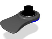
Halterung für 3DConnexion SpaceNavigator für Notebooks by herbert_b1
...ung für 3dconnexion spacenavigator für notebooks by herbert_b1
thingiverse
support for 3dconnexion spacenavigator for notebooks
thingiverse
free

Deckplatte für Playmobil Möbel (Schrank für Herd etc) by charly52
...kplatte für playmobil möbel (schrank für herd etc) by charly52
thingiverse
deckplatte für playmobil möbel (schrank für herd etc)
thingiverse
free

Haken für Kederschiene 7mm für Dtbd-Dachzelt by Paku_ia
...dtbd-dachzelt by paku_ia
thingiverse
haken für ddbd-dachzelt. zur montage wir die haken einfach in die kederleiste eingeschoben.
thingiverse
free

Öse für Kederschiene 7mm für Dtbd-Dachzelt by Paku_ia
...ia
thingiverse
besfestigungsöse für ddbd-dachzelt. zur montage wir die befestigungsöse einefach in die kederleiste eingeschoben.
thingiverse
free

Case für REPRAP_DISCOUNT_FULL_GRAPHIC_SMART_CONTROLLER by Rolfiklein
..._full_graphic_smart_controller by rolfiklein
thingiverse
gehäuse für das weit verbreitete grafik display mit schalter für licht.
thingiverse
free
Haken für Dusche by Pascal_1966
...haken für dusche by pascal_1966
thingiverse
haken für dusche
thingiverse
free

Printhalterung für Schaltschrank by nikibalboa
...printhalterung für schaltschrank by nikibalboa
thingiverse
platinenaufnahme für schienenmontage
thingiverse
free

Adapter für Schläuche by jensatweb
...adapter für schläuche by jensatweb
thingiverse
adapter für poolschläuche
Wheel
archibase_planet
free

Wheel
...l steering control steering wheel
wheel ship steering wheel n060215 - 3d model (*.gsm+*.3ds+*.max) for exterior 3d visualization.
3d_ocean
$14
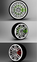
Wheel
...wheel
3docean
car rim car wheel rim wheel
high poly car wheel design. 16,840 polys
3d_export
free
wheel
...wheel
3dexport
wheel
3d_export
free
wheel
...wheel
3dexport
wheel
3d_export
free
Wheel
...wheel
3dexport
wheel
3d_export
$5

wheel
...wheel
3dexport
wheel for car.
3d_export
$5
wheel
...wheel
3dexport
car wheel
3d_export
$5
wheel
...wheel
3dexport
car wheel
3d_export
$5

wheel
...wheel
3dexport
car wheel
3d_export
$5
wheel
...wheel
3dexport
car wheel
Stand
turbosquid
$50

stand watermelon stand
...yalty free 3d model stand watermelon stand for download as ma on turbosquid: 3d models for games, architecture, videos. (1528284)
archibase_planet
free
Stand
...stand
archibase planet
stand post pole
stand - 3d model for interior 3d visualization.
archibase_planet
free
Stand
...stand
archibase planet
stand sport barbell
stand kettler - 3d model for interior 3d visualization.
archibase_planet
free
Stand
...stand
archibase planet
locker drawer stand
stand 897810 - 3d model for interior 3d visualization.
archibase_planet
free
Stand
...stand
archibase planet
stand rack post
stand 2 - 3d model for interior 3d visualization.
archibase_planet
free
Stand
...stand
archibase planet
stand storefront shelving
stand 3 - 3d model for interior 3d visualization.
archibase_planet
free

Stand
...stand
archibase planet
stand shelf shelving
stand 4 - 3d model for interior 3d visualization.
archibase_planet
free

Stand
...stand
archibase planet
stand post stall
stand 5 - 3d model for interior 3d visualization.
archibase_planet
free
Stand
...stand
archibase planet
stand post stall
stand 6 - 3d model for interior 3d visualization.
archibase_planet
free
Stand
...stand
archibase planet
stand post shelving
stand 7 - 3d model for interior 3d visualization.