Thingiverse
Zaribo Y axis lead screw conversion by slink6
by Thingiverse
Last crawled date: 3 years ago
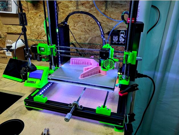
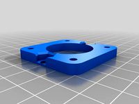
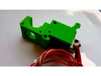
This is a mount for a nema 17 motor mounting to a 3030 extrusion. This orients the motor so that you can replace the belt driven Y axis with a lead screw.
Links below for the lead screw, Tnut, and Tnut holder. Your particular application may vary with the difference in height between the 3030 extrusion and your Y axis bed plate. I needed to add two washers as spacers to maintain alignment of the lead screw from the motor to the idler bearing.
I found the easiest way to acheive proper alignment between the Tnut holder, motor, and idler bearing was:
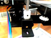
-First mount the Tnut and holder to the Ycarrage plate
-install the motor / motor mount and idler bearing onto the 3030 extrusion. Install the mounting hardware but do not tighten down full into the 3030 channel nuts at this time. They should move freely along the extrusion with minimal effort.
-insert the lead screw through the idler bearing, and into the Tnut. Continue screwing the lead screw until you can insert it until the coupling, attaching it to the motor.
at this point it will be obvious if you need to adjust the heights (raise the motor mount and the idler bearing, and or lower the Tnut holder by adding a spacer between the plate and the holder. I printed a small spacer block to lower the holder, and used washers to raise the motor mount and the idler bearing)
-assuming at this point the 3 parts (motor mount, Tnut holder, and idler bearing) are in vertical alignment with one another we now have to achieve horizontal alignment. Misalignment will be obvious as the Tnut will bind on the lead screw if alignment is too far off, and feel more resistant when slightly off.
-position the motor mount and idler bearing so that the lead screw appears as straight as possible. manually rotate the lead screw to move the bed to the rear. The motor mount should be loose enough that the tension of a misaligned lead screw will move it to a more aligned position as you get closer to the motor mount with the Tnut holder. If you need to, manually slide the motor mount along until there is the least amount of resistance possible when you manually turn the screw. Move the bed to it's most forward position and do the same with the Idler bearing, trying to achieve the least amount of resistance when you turn the screw.
-Move the bed back to the rear most position, continue to correct the position of the motor mount if needed and tighten the motor mount down to the extrusion.
-Now again manually turn the screw to move the bed to the most forward position, adjusting the idler bearing's position if required. Once you find the lowest resistance position, tighten down the idler bearing.
-Now that both the motor mount and the idler bearing are tightened down, manually rotate the screw through the entire possible travel distance the bed can make, all the way back and all the way forward. The resistance felt as you turn the screw should be minimal, and constant and not varied at this point.
if you are confident in your motor and idler position but still feel increased resistance towards the fully forward and fully rearward positions, the likely issue is that your vertical alignment is off. Binding will be most obvious at the extreme positions, nearest the motor and the idler. Re assess the height difference between your motor, idler, and Tnut. Adjust the number of washers you are using to raise the motor and idler or lower the Tnut holder by using a thicker spacer if needed.
-when you have achieved proper alignment in both vertical and horizontal you will not notice an increase in resistance when you turn the screw at the maximum forward and rearward positions.
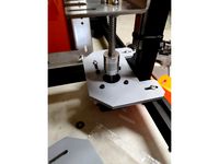
-You will need to mount your Yaxis end stop switch to the motor mount (see my picture) The position will depend on the height of your Y carriage plate. I positioned mine after printing when I could fit the switch to the plate properly. Drill 2 small holes and screw into the plastic.
I use lithium grease on the lead screw to aid in smooth operation, but many do not. This seems to be up to you.
-Use the prusa calculator to determine your new steps / mm value to input to your firmware's Yaxis steps/mm value.
(if you use a 2mm pitch, 14mm lead lead screw like I did the value you will use is 228.57)
a word on motor / shaft couples
you have really only two options when it comes to coupling your leadscrew to the motor, either a rigid or flexible coupler.
The flexible option is the better choice in my opinion, as it will allow for some slight misalignment between the motor and the lead screw. There is an important exception however:
If you are using a large bed / heavy Y carriage plate like I do, you will want to use a rigid coupling. The inertia of the larger bed/carriage plate will cause a flexable coupling to expand slightly (like a spring) when the motor changes direction rapidly. This may not be an issue with a lighter bed/carriage plate combination.
Links
X axis screw idler
"Oil-Embedded Mounted Sleeve Bearings"https://www.mcmaster.com/#catalog/124/1255/=1d9xeu8
Lead screwhttps://www.aliexpress.com/item/304-stainless-steel-T8-screw-length-500mm-lead-1mm-2mm-3mm-4mm-8mm-10mm-12mm-14mm/32695471104.html?spm=a2g0s.9042311.0.0.73bb4c4dYYWtUt
Tnut the Tnut must match in pitch and lead values to the lead screw you intend to usehttps://www.aliexpress.com/item/T8-eliminate-clearance-nut-anti-backlash-nut-trapezoidal-screw-nut-pictch-2mm-lead-8mm-1pcs/32732745669.html?spm=a2g0s.9042311.0.0.73bb4c4dYYWtUt
Tnut blockhttps://www.aliexpress.com/item/T8-Trapezoidal-Lead-Screw-Nut-Housing-Bracket-For-3D-Printer-Parts-Reprap-CNC-Free-Shipping/32846308484.html?spm=a2g0s.9042311.0.0.73bb4c4dYYWtUt
Rigid couplinghttps://www.amazon.com/gp/product/B01M8QXY8N/ref=oh_aui_detailpage_o02_s00?ie=UTF8&psc=1
Flexible couplinghttps://www.amazon.com/gp/product/B01HBPHSII/ref=oh_aui_detailpage_o03_s00?ie=UTF8&psc=1
Prusa Calculatorhttps://www.prusaprinters.org/calculator/
Links below for the lead screw, Tnut, and Tnut holder. Your particular application may vary with the difference in height between the 3030 extrusion and your Y axis bed plate. I needed to add two washers as spacers to maintain alignment of the lead screw from the motor to the idler bearing.
I found the easiest way to acheive proper alignment between the Tnut holder, motor, and idler bearing was:
-First mount the Tnut and holder to the Ycarrage plate
-install the motor / motor mount and idler bearing onto the 3030 extrusion. Install the mounting hardware but do not tighten down full into the 3030 channel nuts at this time. They should move freely along the extrusion with minimal effort.
-insert the lead screw through the idler bearing, and into the Tnut. Continue screwing the lead screw until you can insert it until the coupling, attaching it to the motor.
at this point it will be obvious if you need to adjust the heights (raise the motor mount and the idler bearing, and or lower the Tnut holder by adding a spacer between the plate and the holder. I printed a small spacer block to lower the holder, and used washers to raise the motor mount and the idler bearing)
-assuming at this point the 3 parts (motor mount, Tnut holder, and idler bearing) are in vertical alignment with one another we now have to achieve horizontal alignment. Misalignment will be obvious as the Tnut will bind on the lead screw if alignment is too far off, and feel more resistant when slightly off.
-position the motor mount and idler bearing so that the lead screw appears as straight as possible. manually rotate the lead screw to move the bed to the rear. The motor mount should be loose enough that the tension of a misaligned lead screw will move it to a more aligned position as you get closer to the motor mount with the Tnut holder. If you need to, manually slide the motor mount along until there is the least amount of resistance possible when you manually turn the screw. Move the bed to it's most forward position and do the same with the Idler bearing, trying to achieve the least amount of resistance when you turn the screw.
-Move the bed back to the rear most position, continue to correct the position of the motor mount if needed and tighten the motor mount down to the extrusion.
-Now again manually turn the screw to move the bed to the most forward position, adjusting the idler bearing's position if required. Once you find the lowest resistance position, tighten down the idler bearing.
-Now that both the motor mount and the idler bearing are tightened down, manually rotate the screw through the entire possible travel distance the bed can make, all the way back and all the way forward. The resistance felt as you turn the screw should be minimal, and constant and not varied at this point.
if you are confident in your motor and idler position but still feel increased resistance towards the fully forward and fully rearward positions, the likely issue is that your vertical alignment is off. Binding will be most obvious at the extreme positions, nearest the motor and the idler. Re assess the height difference between your motor, idler, and Tnut. Adjust the number of washers you are using to raise the motor and idler or lower the Tnut holder by using a thicker spacer if needed.
-when you have achieved proper alignment in both vertical and horizontal you will not notice an increase in resistance when you turn the screw at the maximum forward and rearward positions.
-You will need to mount your Yaxis end stop switch to the motor mount (see my picture) The position will depend on the height of your Y carriage plate. I positioned mine after printing when I could fit the switch to the plate properly. Drill 2 small holes and screw into the plastic.
I use lithium grease on the lead screw to aid in smooth operation, but many do not. This seems to be up to you.
-Use the prusa calculator to determine your new steps / mm value to input to your firmware's Yaxis steps/mm value.
(if you use a 2mm pitch, 14mm lead lead screw like I did the value you will use is 228.57)
a word on motor / shaft couples
you have really only two options when it comes to coupling your leadscrew to the motor, either a rigid or flexible coupler.
The flexible option is the better choice in my opinion, as it will allow for some slight misalignment between the motor and the lead screw. There is an important exception however:
If you are using a large bed / heavy Y carriage plate like I do, you will want to use a rigid coupling. The inertia of the larger bed/carriage plate will cause a flexable coupling to expand slightly (like a spring) when the motor changes direction rapidly. This may not be an issue with a lighter bed/carriage plate combination.
Links
X axis screw idler
"Oil-Embedded Mounted Sleeve Bearings"https://www.mcmaster.com/#catalog/124/1255/=1d9xeu8
Lead screwhttps://www.aliexpress.com/item/304-stainless-steel-T8-screw-length-500mm-lead-1mm-2mm-3mm-4mm-8mm-10mm-12mm-14mm/32695471104.html?spm=a2g0s.9042311.0.0.73bb4c4dYYWtUt
Tnut the Tnut must match in pitch and lead values to the lead screw you intend to usehttps://www.aliexpress.com/item/T8-eliminate-clearance-nut-anti-backlash-nut-trapezoidal-screw-nut-pictch-2mm-lead-8mm-1pcs/32732745669.html?spm=a2g0s.9042311.0.0.73bb4c4dYYWtUt
Tnut blockhttps://www.aliexpress.com/item/T8-Trapezoidal-Lead-Screw-Nut-Housing-Bracket-For-3D-Printer-Parts-Reprap-CNC-Free-Shipping/32846308484.html?spm=a2g0s.9042311.0.0.73bb4c4dYYWtUt
Rigid couplinghttps://www.amazon.com/gp/product/B01M8QXY8N/ref=oh_aui_detailpage_o02_s00?ie=UTF8&psc=1
Flexible couplinghttps://www.amazon.com/gp/product/B01HBPHSII/ref=oh_aui_detailpage_o03_s00?ie=UTF8&psc=1
Prusa Calculatorhttps://www.prusaprinters.org/calculator/
Similar models
thingiverse
free
Seckit SkGo2 mod - Stepper mount for dual steppers configuration by stevenvo
... best position for your mount to be.
once you find that the plate can move up and down smoothly, tighten the screws on the mount
thingiverse
free

3030 bearing holder by peanutwarrior
...3030 bearing holder by peanutwarrior
thingiverse
bracket for mounting a linear bearing block to 3030 extrusion
thingiverse
free

Ender 3 Pro Y axis motor mount by dmbutyugin
...nside the 4040 aluminium extrusion so that it touches the front idler with the flat side. reinsert the belt into the mount plate.
thingiverse
free

T-Rex2 Ball Screw Mounts by notnyt
...er insert and tighten the top t-nut.
install motor and coupling. push coupling up as high as you can without touching the mount.
thingiverse
free
Lead screw bearing holder with bracket by Franivelius
...e lead screw bearing holder and also some brackets so i created this monster. bearing holder is aligned to z motor mount bracket.
thingiverse
free

Wilson II Z axis alignment tool by ant0ny
...leadscew nut in place attach a couple of these to assist in lining up the leadscrew and motor before tightening the motor screws.
thingiverse
free
Belt driven Z upgrade by MarcusVoss
...idlers)
-two m5x8mm screws and two m5 nuts to mount the kfl008 bearing.
my rod holders: https://www.thingiverse.com/thing:2851231
thingiverse
free

LM8UU Bearing Tight Fit Holder by TalStein
...n printed correctly, this mount has zero play when trying to move the bearing inside the mount, which is was what i was after :).
thingiverse
free

Serious business Bear MK2, MK2.5, MK3 y-axis replacement by zbrozek
...2019-01-01
uploaded fresh source and added some printability features to the motor mount.
2019-02-21
updated the e3d idler slide.
thingiverse
free

Zaribo X axis lead screw conversion by slink6
...s://www.prusaprinters.org/calculator/
tinker cad project with zaribo x/z axis mock-uphttps://www.tinkercad.com/things/7qphkkyiecp
Slink6
thingiverse
free

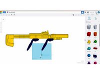
ODST SMG Vive rifle by slink6
... magnetic attachements for htc vive controllers, scaled and split into printable pieces.
http://www.thingiverse.com/thing:2138869
thingiverse
free
ODST SMG Vive rifle by slink6
...ing power then the smaller magnets in the original design.
magnets used: http://www.kjmagnetics.com/proddetail.asp?prod=bx8c4-n52
thingiverse
free

Neato Botvac wheel drive gear by slink6
...rinting of the teeth, and should be able to be press fitted together. i did not need to use glue once the supports were removed.
thingiverse
free

ODST SMG Vive rifle by slink6
...they disconnected too easily for my taste.
the odst smg model was reposted by rainyfire.http://www.thingiverse.com/thing:2018387
thingiverse
free
Zaribo X axis lead screw conversion by slink6
...s://www.prusaprinters.org/calculator/
tinker cad project with zaribo x/z axis mock-uphttps://www.tinkercad.com/things/7qphkkyiecp
Zaribo
thingiverse
free

ZARIBO R3 COVER
...zaribo r3 cover
thingiverse
un petit essai pour ma zaribo 220.
thingiverse
free
Extruder cover for Zaribo 220 or 320 by bartijanos
...artijanos
thingiverse
modified extruder cover to use with prusa mk2 zaribo. corners rounded to keep the original zaribo design.
thingiverse
free
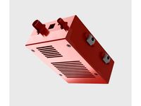
Einsy-Box for Zaribo by wschadow
...re nuts are inserted from the top and don't fall out.
zaribo facebook group: https://www.facebook.com/groups/284271408664100/
thingiverse
free

New ZARIBO MK3s LCD Cover by zaribocom
...zaribo lcd cover and new knob for easy and faster management of incremental values on 2004 lcd screen.
designed by m.araz @zaribo
thingiverse
free

LED Holder Zaribo
...re is a left an right part
led - https://www.amazon.de/gp/product/b07h4mwgmj/ref=ppx_yo_dt_b_asin_title_o01_s00?ie=utf8&psc=1
thingiverse
free

Zaribo Z Motors Top mounts
...zaribo z motors top mounts
thingiverse
zaribo z motor mounts for top of the frame. mirror along x axis for the left one.
thingiverse
free

Zaribo LCD knob by Kapplion
... zaribo research and development and put their logo on it.
i printed my with a .4 nozzle but a .2 -.25 should make a better look.
thingiverse
free

Zaribo X axis for Tatara frame by Afterschnitzel
...zaribo x axis for tatara frame by afterschnitzel
thingiverse
i reworked zaribo rel3 - x axis for tatara frame.
thingiverse
free
haribo/zaribo y idler holder by NeoFromMatrix
...zaribo y idler holder by neofrommatrix
thingiverse
y idler holder for haribo/zaribo (30x30mm aluminium extrusion with 8mm slots)
thingiverse
free
ZARIBO Octodash Octoprint Touchscreen TFT Mount by zaribocom
...splay housing for zaribo printers with the new knob for easy and faster control of incremental values.
designed by m.araz @zaribo
Conversion
3ddd
$1

Conversation Seat
...шетка
the conversation seat made in englandhttp://www.squintlimited.com/products/the_conversation_seat/gold
+ max 2011
3d_export
$10

Converse 3D Model
...converse 3d model
3dexport
converse shoe pc unix mac
converse 3d model electropainter17075 38067 3dexport
turbosquid
$100

converse-shoe
...quid
royalty free 3d model converse-shoe for download as c4d on turbosquid: 3d models for games, architecture, videos. (1398427)
turbosquid
$10

Conversation Furniture
... available on turbo squid, the world's leading provider of digital 3d models for visualization, films, television, and games.
turbosquid
$7

Converse Allstars
... available on turbo squid, the world's leading provider of digital 3d models for visualization, films, television, and games.
design_connected
$16

Conversation Club Chair
...conversation club chair
designconnected
donghia conversation club chair chairs computer generated 3d model. designed by n/a.
design_connected
$27

Hemicycle Conversation Chair
...rsation chair
designconnected
ligne roset hemicycle conversation chair computer generated 3d model. designed by nigro, philippe.
3d_export
$24

Converse keds 3D Model
...converse keds 3d model
3dexport
converse all star ked shoe clothes sports
converse keds 3d model vermi1ion 26201 3dexport
3ddd
$1

Converse All-Star Shoes
...converse all-star shoes
3ddd
кеды , обувь
converse all-star shoes
design_connected
$18

CONVERSE Jack Purcell Sneakers
...converse jack purcell sneakers
designconnected
converse jack purcell sneakers computer generated 3d model.
Axis
3ddd
$1

Мария Axis
...
3ddd
кухня , классическая , axis
модель кухни.
3d_export
$22
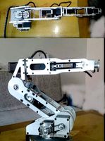
Axis robot 6-axis robotic arm
...ing parts drawings, standard parts purchased parts list, can be produced directly according to the drawings, welcome to download!
3ddd
free

Versatile Axis
...ddd
nexus , плитка
http://bvtileandstone.com/ceramic-porcelain/versatile-axis/
3d_export
$19
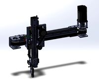
robot 2 axis
...robot 2 axis
3dexport
robot 2 axis
turbosquid
$40

Axis R5F
... available on turbo squid, the world's leading provider of digital 3d models for visualization, films, television, and games.
turbosquid
$40

Axis S5F
... available on turbo squid, the world's leading provider of digital 3d models for visualization, films, television, and games.
turbosquid
$30

Axis Athlon
... available on turbo squid, the world's leading provider of digital 3d models for visualization, films, television, and games.
turbosquid
$10

Linear Axis
... available on turbo squid, the world's leading provider of digital 3d models for visualization, films, television, and games.
3d_export
$15

drawing axis
...drawing axis
3dexport
simple rendering of the scene file
3ddd
$1

versatile axis ARC
...versatile axis arc
3ddd
versatile , плитка
versatile axis arc red dot design award
Y
turbosquid
$1

Tetera y Galletas y Caf
... available on turbo squid, the world's leading provider of digital 3d models for visualization, films, television, and games.
3ddd
$1

Смеситель Y-CON
...смеситель y-con
3ddd
смеситель , y-con
смеситель y-con
3ddd
$1

Y-Chair
...y-chair
3ddd
tom dixon
y-chair designed by tom dixon,
3ds max + obj, corona
3ddd
$1

Y Chair compilation
....net/products/us/y-chair-sled-base
y chair swivel basehttp://www.tomdixon.net/products/us/y-chair-swivel-base
turbosquid
$190
Y-8
...y-8
turbosquid
royalty free 3d model y-8 for download as max on turbosquid: 3d models for games, architecture, videos. (1658891)
turbosquid
$7

Bench Y
...turbosquid
royalty free 3d model bench y for download as obj on turbosquid: 3d models for games, architecture, videos. (1488746)
turbosquid
$15

bonePile Y
...oyalty free 3d model bonepile y for download as blend and obj on turbosquid: 3d models for games, architecture, videos. (1546374)
turbosquid
$7

Y for Yarn
...d
royalty free 3d model y for yarn model for download as max on turbosquid: 3d models for games, architecture, videos. (1699732)
turbosquid
$2
FONT Y
...quid
royalty free 3d model font y for download as ma and obj on turbosquid: 3d models for games, architecture, videos. (1549457)
3ddd
$1

WOOD-y
...wood-y
3ddd
wooden guy
Screw
3d_export
$5
screw
...screw
3dexport
screw
turbosquid
$29

Screw driver and screws
... available on turbo squid, the world's leading provider of digital 3d models for visualization, films, television, and games.
3d_ocean
$2
Screw
... steel twist wood screw
screw 3d model in 2 different materials real world scale rendered with mental ray file formats: .max .obj
3d_ocean
$4

Screw
...n
3d bolt male mechanic metal nut parts prop propeller schraube schraubenmutter screw steel twist
screw 3d model, clean modeling.
turbosquid
$2
screw
...crew
turbosquid
royalty free 3d model screw for download as on turbosquid: 3d models for games, architecture, videos. (1198271)
turbosquid
free
Screw
...screw
turbosquid
free 3d model screw for download as obj on turbosquid: 3d models for games, architecture, videos. (1240851)
3d_ocean
$2
Frame Screw
...frame screw
3docean
construction screw
a frame screw and plug.
turbosquid
$27
screw
...w
turbosquid
royalty free 3d model screw for download as max on turbosquid: 3d models for games, architecture, videos. (1334064)
turbosquid
$20

SCREW
...
turbosquid
royalty free 3d model screw for download as sldas on turbosquid: 3d models for games, architecture, videos. (729733)
turbosquid
$1
Screws
...
turbosquid
royalty free 3d model screws for download as max on turbosquid: 3d models for games, architecture, videos. (1640360)
Lead
turbosquid
$25

Lead Sled
... available on turbo squid, the world's leading provider of digital 3d models for visualization, films, television, and games.
turbosquid
$20

pencil leads
... available on turbo squid, the world's leading provider of digital 3d models for visualization, films, television, and games.
turbosquid
$10

Lead Pipe
... available on turbo squid, the world's leading provider of digital 3d models for visualization, films, television, and games.
turbosquid
$35

Leagoo Lead 7
... available on turbo squid, the world's leading provider of digital 3d models for visualization, films, television, and games.
3ddd
$1

leaded Glass
...glass
3ddd
стекло витраж
стаки не свернуты длч удобства подгонки под размеры.материалы легко меняються по вкусу.
текстуры+мах 10.
turbosquid
$15

LAS LEAD ARMCHAIRS
...del las lead armchairs for download as 3ds, max, obj, and fbx on turbosquid: 3d models for games, architecture, videos. (1443555)
turbosquid
$19

2 Black Lead Pencils
... available on turbo squid, the world's leading provider of digital 3d models for visualization, films, television, and games.
turbosquid
$9

Mechanical Pencil Lead Refill
... available on turbo squid, the world's leading provider of digital 3d models for visualization, films, television, and games.
turbosquid
$1

Antique lead crystal vase
...free 3d model antique lead crystal vase for download as blend on turbosquid: 3d models for games, architecture, videos. (1405722)
turbosquid
$60

Lead Bricks for Radiation Shielding
...icks for radiation shielding for download as ma, fbx, and obj on turbosquid: 3d models for games, architecture, videos. (1622529)