Thingiverse
Z Axis Optical Endstop for Geeetech Prusa I3 Pro by DougInAZ
by Thingiverse
Last crawled date: 3 years ago
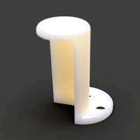
Update 1/28/18 I added a retainer to secure the stop flag in its holder. I relied on a friction fit on an earlier version and when I replaced it, I found there wasn't anything to secure the flag. You can mount it either way in the holder, depending upon whether you are using a printed flag or a thinner one made out of plastic or card-stock.
Added 5/29/18. Originally I used a printed flag that was painted at the end. After a long while, I started getting inconsistent Z homing. I believe the paint was scratched somewhere along the line, and it was no longer opaque. I replaced it with a flag made out of credit-card plastic and it the Z-home consistency was restored. FWIW, I also painted the end if the flag black with a black marking pen.
UPDATE 1/30/17 The holes in the printer frame and/or the holes in the bracket that mounts to the printer frame are over-size for the 2.5 mm screws that Geeetech originally furnished for the micro switch. Also, the holes on the frame of my printer appear not to be parallel to the horizontal line of the printer frame. There isn't any problem with the frame bracket being out of square with the frame as far as the flag actuating the optical module, but the over-size holes allow the optical module to be moved up and down if the bracket holding the optical module is bumped inadvertently. This can move the end point and allow the extruder to end up too high or low when homed. I've found it is best to push the bracket to its lowest position and then make sure the screws are tight. Another potential fix is to switch to 3 mm screws and/or place some contact cement on the bracket before mounting it to the frame and make sure it is in the lowest position when fixed in place.
UPDATE 12/29: I've been using this for almost a month now, and am very pleased with the way it works. It seems very repeatable. Between this and the nut keepers on the printer bed, my printer bed holds adjustment much better than it used to when I got it a year ago.
After having two micro switches fail in less than a year of use, the option of using an optical sensor end stop switch seemed like a worthwhile thing to try. Switches that do not provide a consistent switch point can be tolerated in the X and Y axis, but precision is a necessity in the Z axis if your bed control is manual.
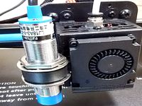
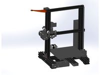
The two printed assemblies here, plus a purchased optical module provide an optical endstop that replaces the microswitch on the Z axis of Geeetech I3 Pro printers. It can probably be adapted to other printers that use the same metal brackets as the Pro series on the X carriage.
First, my thanks to Ablapo for his design, http://www.thingiverse.com/thing:27544, which provided the inspiration. I wish I could have used it as-designed in my printer.
Besides the printed parts, The following parts are needed:
1 Ramps 1.4 Optical Endstop and cable, eBay, Aliexpress or other.
1 square post for connecting 5V power to endstop cable (or solder to board (recommended))
Misc soldering tools and shrink tube.
2 #4 x 1/2 inch SAE sheet metal screws or similar size metric sheet metal or machine screws for mounting optical switch to the printed bracket..
1 3MM cap screw as furnished by Geeetech for Z-Endstop adjustment (to provide adjustment of optical sensor).
1 Spring, as furnished for Z-End stop by Geeetech;
1 6d Finishing Nail or similar smooth steel rod approximately 0.092 in. diameter to stabilize the position of the optical sensor.
2 short #4 sheet metal screws or machine screws to hold the stop flag coarse adjustment in the movable carriage. These are not needed if the flag is glued or friction-fitted into the flag holder.
Steel washers, 3mm 3 for the spring and cap screw. a couple more if you use screws to hold the flag into the bracket.
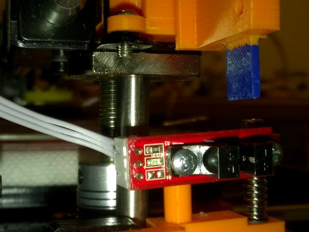
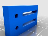
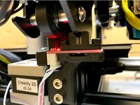
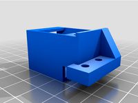
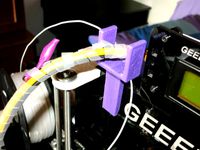
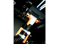
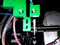
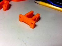
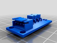
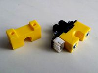
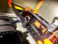
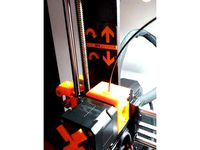
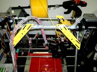
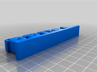
The assembly that is mounted on the X axis carriage holds the stop flag which enters the gate in the optical switch when nearing the stop point. This assembly allows a coarse height adjustment of the stop flag. It can accommodate a wide range of extruders by raising or lowering the stop flag fixed position. This allows the fine adjustment on the fixed assembly to have a limited adjustment range without the spring being too tight or too loose.
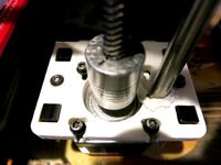
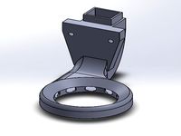
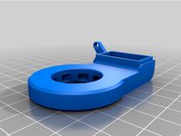
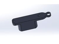
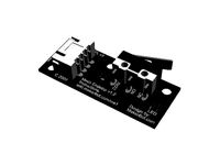
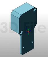
The assembly mounted on the frame attaches to the mounting holes that were used for the microswitch. It provides fine Z-adjustment of the optical sensor using a 3mm machine screw. A smooth steel rod on the sensor holder moves in a clearance hole and keeps the sensor in alignment.
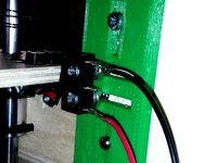
The optical sensor is powered by 5vdc which can be tapped from the main controller board or the display panel. The newer GT256 control boards have 3 pins available for powering a BL Touch. That is an easy place to get 5 VDC. The other two wires of the optical sensor connect to the existing wires that connected to the micro switch. These two wires provide a 5v ground and the output signal used by the processor board. Use a voltmeter connected to 12v low to determine which is the signal and mark it for connection to the optical module.
I added a knob for adjustment, but the screw furnished with the printer may not be long enough to use it without compressing the spring more than desirable. If you want to use a knob, use a longer screw with a nut run up tightly against the head and insert it in the bottom of the fixed frame piece. Put the knob on the top of the movable piece, where the adjustment cap screw head is in the pictures. It looks like there will have to be a spacer under the knob to clear the sensor. You can use the washers included; they can be scaled up in size ant thickness to do the job.
It's worth mentioning that the photos show development parts and in most cases are not the same as submitted here; I never updated the parts on my printer. If I screwed up, and the changes don't work, please let me know, so I can fix it.
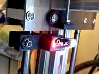
The LED on the sensor lights when the flag is not blocking the path. In practice, the LED never extinguishes. When the flag triggers it momentarily, the end point is sensed and the stepper motors stop. In my case, the LED remains lighted after the motors stop, however it is not at full brightness, which indicates there is a lot of noise in the module. A capacitor across the module might be helpful, but the switch point seems very repeatable as noted by the stopped position of the stepper motors. If anyone tries to correct this situation, let me know so I can add your findings. This printer is an EMI nightmare; it drives my digital caliper crazy if it is within several feet of it.
UPDATE 12-2-16
I added knob2. This offers another way of adding a knob to the adjusting screw. It is attached to the head of the cap screw by heating the screw with a soldering iron and pressing it into the knob. If it comes off when it cools, a drop of CA glue might be enough to keep it in place more or less permanently. The best way to get it on straight is to drop the hot screw into a clearance hole in a piece of wood or other material and then press the knob firmly in place over the head. It can be reheated (at the base of the head) and repeated as necessary. The hole in the front of the printer base for the Y carriage belt adjustment is a good hole to use. Put a washer on the screw to make sure the screw is fully supported when you press against it.
UPDATE 12-3-16
I shortened the vertical blade on the X carriage base to get it out of the way of the knob and added it as Base 2.... The change shouldn't interfere with use on the target printer.
Notes:
The pitch of a 3mm adjustment screw is 0.5 mm or 0.020 in. A quarter turn of the knob or screw moves the Z set point 0.125 mm or 0.005 in.
The downside of using a square pin connector on the power to the optical module is that if the power connector happens to get knocked off, the carriage will crash into the bed when homed.
I'm not using the latest parts, but when I see something that can be improved, I make a change. The downside is that I may upset something that I don't see. The only way I'll know is if I get feedback. If you run into something that doesn't fit or work well, please let me know and I'll try to fix it.
12/6 added photo of Knob2 pressed onto the original z-adjust screw.
Added 5/29/18. Originally I used a printed flag that was painted at the end. After a long while, I started getting inconsistent Z homing. I believe the paint was scratched somewhere along the line, and it was no longer opaque. I replaced it with a flag made out of credit-card plastic and it the Z-home consistency was restored. FWIW, I also painted the end if the flag black with a black marking pen.
UPDATE 1/30/17 The holes in the printer frame and/or the holes in the bracket that mounts to the printer frame are over-size for the 2.5 mm screws that Geeetech originally furnished for the micro switch. Also, the holes on the frame of my printer appear not to be parallel to the horizontal line of the printer frame. There isn't any problem with the frame bracket being out of square with the frame as far as the flag actuating the optical module, but the over-size holes allow the optical module to be moved up and down if the bracket holding the optical module is bumped inadvertently. This can move the end point and allow the extruder to end up too high or low when homed. I've found it is best to push the bracket to its lowest position and then make sure the screws are tight. Another potential fix is to switch to 3 mm screws and/or place some contact cement on the bracket before mounting it to the frame and make sure it is in the lowest position when fixed in place.
UPDATE 12/29: I've been using this for almost a month now, and am very pleased with the way it works. It seems very repeatable. Between this and the nut keepers on the printer bed, my printer bed holds adjustment much better than it used to when I got it a year ago.
After having two micro switches fail in less than a year of use, the option of using an optical sensor end stop switch seemed like a worthwhile thing to try. Switches that do not provide a consistent switch point can be tolerated in the X and Y axis, but precision is a necessity in the Z axis if your bed control is manual.
The two printed assemblies here, plus a purchased optical module provide an optical endstop that replaces the microswitch on the Z axis of Geeetech I3 Pro printers. It can probably be adapted to other printers that use the same metal brackets as the Pro series on the X carriage.
First, my thanks to Ablapo for his design, http://www.thingiverse.com/thing:27544, which provided the inspiration. I wish I could have used it as-designed in my printer.
Besides the printed parts, The following parts are needed:
1 Ramps 1.4 Optical Endstop and cable, eBay, Aliexpress or other.
1 square post for connecting 5V power to endstop cable (or solder to board (recommended))
Misc soldering tools and shrink tube.
2 #4 x 1/2 inch SAE sheet metal screws or similar size metric sheet metal or machine screws for mounting optical switch to the printed bracket..
1 3MM cap screw as furnished by Geeetech for Z-Endstop adjustment (to provide adjustment of optical sensor).
1 Spring, as furnished for Z-End stop by Geeetech;
1 6d Finishing Nail or similar smooth steel rod approximately 0.092 in. diameter to stabilize the position of the optical sensor.
2 short #4 sheet metal screws or machine screws to hold the stop flag coarse adjustment in the movable carriage. These are not needed if the flag is glued or friction-fitted into the flag holder.
Steel washers, 3mm 3 for the spring and cap screw. a couple more if you use screws to hold the flag into the bracket.
The assembly that is mounted on the X axis carriage holds the stop flag which enters the gate in the optical switch when nearing the stop point. This assembly allows a coarse height adjustment of the stop flag. It can accommodate a wide range of extruders by raising or lowering the stop flag fixed position. This allows the fine adjustment on the fixed assembly to have a limited adjustment range without the spring being too tight or too loose.
The assembly mounted on the frame attaches to the mounting holes that were used for the microswitch. It provides fine Z-adjustment of the optical sensor using a 3mm machine screw. A smooth steel rod on the sensor holder moves in a clearance hole and keeps the sensor in alignment.
The optical sensor is powered by 5vdc which can be tapped from the main controller board or the display panel. The newer GT256 control boards have 3 pins available for powering a BL Touch. That is an easy place to get 5 VDC. The other two wires of the optical sensor connect to the existing wires that connected to the micro switch. These two wires provide a 5v ground and the output signal used by the processor board. Use a voltmeter connected to 12v low to determine which is the signal and mark it for connection to the optical module.
I added a knob for adjustment, but the screw furnished with the printer may not be long enough to use it without compressing the spring more than desirable. If you want to use a knob, use a longer screw with a nut run up tightly against the head and insert it in the bottom of the fixed frame piece. Put the knob on the top of the movable piece, where the adjustment cap screw head is in the pictures. It looks like there will have to be a spacer under the knob to clear the sensor. You can use the washers included; they can be scaled up in size ant thickness to do the job.
It's worth mentioning that the photos show development parts and in most cases are not the same as submitted here; I never updated the parts on my printer. If I screwed up, and the changes don't work, please let me know, so I can fix it.
The LED on the sensor lights when the flag is not blocking the path. In practice, the LED never extinguishes. When the flag triggers it momentarily, the end point is sensed and the stepper motors stop. In my case, the LED remains lighted after the motors stop, however it is not at full brightness, which indicates there is a lot of noise in the module. A capacitor across the module might be helpful, but the switch point seems very repeatable as noted by the stopped position of the stepper motors. If anyone tries to correct this situation, let me know so I can add your findings. This printer is an EMI nightmare; it drives my digital caliper crazy if it is within several feet of it.
UPDATE 12-2-16
I added knob2. This offers another way of adding a knob to the adjusting screw. It is attached to the head of the cap screw by heating the screw with a soldering iron and pressing it into the knob. If it comes off when it cools, a drop of CA glue might be enough to keep it in place more or less permanently. The best way to get it on straight is to drop the hot screw into a clearance hole in a piece of wood or other material and then press the knob firmly in place over the head. It can be reheated (at the base of the head) and repeated as necessary. The hole in the front of the printer base for the Y carriage belt adjustment is a good hole to use. Put a washer on the screw to make sure the screw is fully supported when you press against it.
UPDATE 12-3-16
I shortened the vertical blade on the X carriage base to get it out of the way of the knob and added it as Base 2.... The change shouldn't interfere with use on the target printer.
Notes:
The pitch of a 3mm adjustment screw is 0.5 mm or 0.020 in. A quarter turn of the knob or screw moves the Z set point 0.125 mm or 0.005 in.
The downside of using a square pin connector on the power to the optical module is that if the power connector happens to get knocked off, the carriage will crash into the bed when homed.
I'm not using the latest parts, but when I see something that can be improved, I make a change. The downside is that I may upset something that I don't see. The only way I'll know is if I get feedback. If you run into something that doesn't fit or work well, please let me know and I'll try to fix it.
12/6 added photo of Knob2 pressed onto the original z-adjust screw.
Similar models
thingiverse
free

Anet A6 Z switch height adjustment by BrienAllison
...cally go before the z carriage hits the bracket before the switch (or you could potentially modify the z carriage to avoid this).
thingiverse
free
Frame Mounted Adjustable Endstop Bracket by 7ofclubs
...ustable bracket so i can mount my mechanical end stop and adjust it. i used 3mmx12mm screws to attach the endstop to the bracket.
thingiverse
free

Anet A2 Prusa Z endstop adjuster
...screw is used for the adjustment and threadlock solution can be applied to the knob to stop it from spinning freely on the screw.
thingiverse
free
Wanhao Duplicator i3 Z Endstop Bracket by evadeninja
...s for the endstop switch, and slots to raise/lower the endstop.
note that newer models of the printer don't require this mod.
thingiverse
free
Optical Endstop Bracket Holder Ender-3 Sensor
... the metal of the ender is 3mm thick, so is the gap of the sensor. for me the metal frame of the x-axis fits nicely into the gap.
thingiverse
free
Geeetech A10 proximity sensor bracket
... bracket
thingiverse
proximity sensor mounting bracket for geeetech a10.
use 3dtouch mounting screws and screw holes for fixing.
thingiverse
free
Printrbot Plus 2.0 Optical Z-endstop Mount by TechnoSwiss
...
bracket for mounting an optical z-endstop on the printrbot plus v2.0 using the mounting holes for the mechanical switch endstop.
thingiverse
free

Optical Endstop Switch Mount for Geeetech G2s by namomo
...witch mount for geeetech g2s by namomo
thingiverse
this is a mount for optical endstop switch for geeetech g2s delta 3d printer.
thingiverse
free

Adjustable Z endstop mount for Sunhokey Prusa i3 by jihartik
...with one screw
note: the part probably doesn't work with the stock hot end & x carriage (i have used it only with e3dv6).
thingiverse
free

Capacitive Z end stop by Berry75
...that fix the hotend stirrup.
i buy the sensor on aliexpress: search for: lj12a3-4-z/by inductive proximity sensor ( the type 4mm)
Douginaz
thingiverse
free
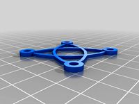
Simple Fan Guard by DougInAZ
...original, but other than that should do about the same job as the original. if you want it thicker, scale it in the z direction.
thingiverse
free

Super Glue Holder by DougInAZ
...se for super glue before i had a 3d printer. now, i find it an essential item to assmeble and patch pla and some other plastics.
thingiverse
free

Soap Tray for Kitchen or bathroom by DougInAZ
...version without drain holes, let me know and i'll add one.
note: the models are sized @ 10x. scale to 0.1 for original size.
thingiverse
free

Nose Clip for anti COVID mask by DougInAZ
...nother version(s) right away.
update 4/17/21 i added a version that fits tighter on my face and is twice as thick in the arms.
thingiverse
free
Holder for X10 Clock by DougInAZ
...the rear feet of the stand. it was really not needed for my use, and probably doesn't need to be used for most applications.
thingiverse
free
Joy Stick Handle for Power Chair by DougInAZ
...meter, with a 11.5 mm circular stop below.
the part has a thin internal brim built into it that has to be removed prior to use.
thingiverse
free
Base for Enermax EAS02S Bluetooth Speaker by DougInAZ
...ne perimeter for the base, and the infill moved the printed thread where they were adjacent. however, it was surprisingly rigid.
thingiverse
free

Tray for Pills, etc. by DougInAZ
...two colors using a y-switching extruder and patched g-code. there is also a small foot. print four and glue them on the bottom.
thingiverse
free

Tether for Drill Chuck Key by DougInAZ
...asy to heat them with a hair dryer and slip them around the 90 deg bend when they were hot. upon cooling, they are a shrink fit.
thingiverse
free

Steering Wheel Spinner Knob for 29x36 mm Wheel by DougInAZ
...ings like this, the question of legality and the risk imposed by having this attached to the steering wheel is borne by the user.
Geeetech
3d_export
free
part right for geeetech acrylic i 3
...part right for geeetech acrylic i 3
3dexport
the engine can be shifted
3d_export
free
cable holder
...cable holder 3dexport for geeetech acrylic i...
thingiverse
free
geeetech a10 by Igor_garbuz
...geeetech a10 by igor_garbuz
thingiverse
model geeetech a10 ( solidworks).
thingiverse
free
geeetech calibration by muffler1979
...geeetech calibration by muffler1979
thingiverse
just a calibration test for the bed on a geeetech
thingiverse
free
Fan for Geeetech proB
...fan for geeetech prob
thingiverse
this is my fan for the geeetech pro b i3.
thingiverse
free

Chain for Geeetech A30
...chain for geeetech a30
thingiverse
this is my personal review of chain for geeetech a30.
thingiverse
free
Zugentlastung Hotend Geeetech A30T / Strain relief Geeetech A30T by 3DDennis1983
...zugentlastung hotend geeetech a30t / strain relief geeetech a30t by 3ddennis1983
thingiverse
zugentlastung hotend geeetech a30t
thingiverse
free
Kettenhalter i3x geeetech by Autark
...kettenhalter i3x geeetech by autark
thingiverse
geeetech i3x
thingiverse
free
Geeetech A10 Fanduct by stefan177gr
...geeetech a10 fanduct by stefan177gr
thingiverse
fanduct for geeetech a10
thingiverse
free
Geeetech filament guide by RicardoZ2018
...geeetech filament guide by ricardoz2018
thingiverse
desing for geeetech i3x
Endstop
thingiverse
free
Endstop-holder for endstop v1.2 by albiuz
...endstop-holder for endstop v1.2 by albiuz
thingiverse
endstop-holder designed for mech endstop v1.2
thingiverse
free
Endstop by 3dboxpro
...endstop by 3dboxpro
thingiverse
endstop
thingiverse
free
Endstop by 1sPiRe
...endstop by 1spire
thingiverse
endstop model for conceptions
thingiverse
free

Endstop holder for Opto or Mechanical endstops by LulzBot
... endstops by lulzbot
thingiverse
these are the standard 1.0 prusa endstops with an added mounting hole for mechanical endstops.
thingiverse
free

Endstop Holder by onurhamdiuzun
...endstop holder by onurhamdiuzun
thingiverse
endstop holder for makerbot endstop and other endstops
thingiverse
free

Endstop Cover
...endstop cover
thingiverse
cover for endstop boards for makerbot design.
thingiverse
free
Endstop Mount for optical Endstops by Whitehawk2000
...whitehawk2000
thingiverse
use two 20mm m3 screws and nuts to screw the endstop onto the mount and just clip it onto the 8mm rod.
thingiverse
free

C-beam endstop mount for Makerbot type endstops
...c-beam endstop mount for makerbot type endstops
thingiverse
c-beam endstop mount for makerbot type endstop boards.
thingiverse
free

Endstop Mount for MakerBot Mecanical Endstop. by nka
...v-slots carriage.
endstop is screw with m3 (8mm) tapped hole and the endstop hold on the extrusion using a m5 (8mm) and t-nuts.
thingiverse
free
ENDSTOP 10mm by desert500
...endstop 10mm by desert500
thingiverse
endstop
Optical
design_connected
$9
Optic
...optic
designconnected
alessi optic computer generated 3d model. designed by colombo, joe.
3ddd
$1

обои OPTIC
...обои optic
3ddd
в архиве текстуры и фото обоев из коллекции optic.
archive3d
free
Optics 3D Model
...optics 3d model
archive3d
optics
optics - 3d model (*.gsm+*.3ds) for interior 3d visualization.
turbosquid
$49

optical eyewear
...id
royalty free 3d model optical eyewear for download as max on turbosquid: 3d models for games, architecture, videos. (1592243)
3d_ocean
$5

optical mouses
...al mouses
3docean
3d models computer electronics mouse
optical mouses 3d models. realistic mouse model. custom and unique design.
turbosquid
$10
Optic cross
...yalty free 3d model optic cross for download as sldas and ige on turbosquid: 3d models for games, architecture, videos. (1683403)
turbosquid
$7

OPTIC Mirror
... free 3d model optic mirror for download as max, obj, and fbx on turbosquid: 3d models for games, architecture, videos. (1223927)
turbosquid
free

Fiber optics
...d model fiber optics for download as 3ds, obj, fbx, and blend on turbosquid: 3d models for games, architecture, videos. (1211912)
turbosquid
$8

Mouse optical
...3d model mouse optical for download as 3ds, obj, c4d, and fbx on turbosquid: 3d models for games, architecture, videos. (1504476)
turbosquid
free

Optical puzzle
... optical puzzle for download as max, ige, fbx, stl, and sldas on turbosquid: 3d models for games, architecture, videos. (1405925)
I3
3d_export
$10
suv i3
...suv i3
3dexport
suv i3 2013 series
3d_ocean
$89

BMW i3 2012
...y, in real units of measurement, qualitatively and maximally close to the original. model formats: - *.max (3ds max 2008 scanl...
cg_studio
$99

BMW i3 20143d model
...
cgstudio
.3ds .c4d .fbx .lwo .max .obj - bmw i3 2014 3d model, royalty free license available, instant download after purchase.
cg_studio
$99

BMW i3 20123d model
...tudio
.3ds .c4d .fbx .lwo .max .mb .obj - bmw i3 2012 3d model, royalty free license available, instant download after purchase.
cg_studio
$99

BMW i3 20143d model
...tudio
.3ds .c4d .fbx .lwo .max .mb .obj - bmw i3 2014 3d model, royalty free license available, instant download after purchase.
humster3d
$75

3D model of BMW i3 2014
...
buy a detailed 3d model of bmw i3 2014 in various file formats. all our 3d models were created maximally close to the original.
humster3d
$40

3D model of Kitchen Set I3
...uy a detailed 3d model of kitchen set i3 in various file formats. all our 3d models were created maximally close to the original.
3d_ocean
$30
Kitchen set i3
...ensils oven plates shelves sink table ware
kitchen set i3 include 3d models: cooker, oven, sink, cupboards, table, chair, plates.
3d_ocean
$89

BMW i3 2014
...y, in real units of measurement, qualitatively and maximally close to the original. model formats: - *.max (3ds max 2008 scanl...
cg_studio
$99

BMW i3 Concept 20113d model
...i3
.3ds .c4d .fbx .lwo .max .obj - bmw i3 concept 2011 3d model, royalty free license available, instant download after purchase.
Prusa
turbosquid
$2
Frame Filament Guide Clip-On for Prusa Mk3
...rame filament guide clip-on for prusa mk3 for download as stl on turbosquid: 3d models for games, architecture, videos. (1634730)
3d_export
free
prusa i3 mk3s laser mount for opt lasers
...to learn more about the blue laser technology that conceived the cutting and engraving laser heads from opt lasers, please visit:
turbosquid
free
Prusa small printer adapter holder
...er for download as ipt, skp, dwg, dxf, fbx, ige, obj, and stl on turbosquid: 3d models for games, architecture, videos. (1642936)
3d_export
$30

geisha by jonathan adler
...** i did a 3d printing test in the prusa software, you can find it among the attached images.<br>exchange:<br>.blend...
thingiverse
free

Prusa without Prusa (rc2) by madless
...prusa without prusa (rc2) by madless
thingiverse
just the main part of prusa rc2 faceshield, without writing.
enjoy :)
thingiverse
free
Prusa by acejbc
...prusa by acejbc
thingiverse
prusa knob info
m3 8mm screw
thingiverse
free
Prusa house
...prusa house
thingiverse
how prusa house could look like...
thingiverse
free

Prusa Mk2 "Fake Prusa" LCD cover by anraf1001
...r by anraf1001
thingiverse
version of prusa's lcd cover with "fake prusa" instead of "original prusa"
thingiverse
free
Prusa stabilizator by gutiueugen
...prusa stabilizator by gutiueugen
thingiverse
prusa stabilizator
thingiverse
free
Keychain Prusa by rbarbalho
...keychain prusa by rbarbalho
thingiverse
keychain with text prusa.
Axis
3ddd
$1

Мария Axis
...
3ddd
кухня , классическая , axis
модель кухни.
3d_export
$22
Axis robot 6-axis robotic arm
...ing parts drawings, standard parts purchased parts list, can be produced directly according to the drawings, welcome to download!
3ddd
free

Versatile Axis
...ddd
nexus , плитка
http://bvtileandstone.com/ceramic-porcelain/versatile-axis/
3d_export
$19
robot 2 axis
...robot 2 axis
3dexport
robot 2 axis
turbosquid
$40
Axis R5F
... available on turbo squid, the world's leading provider of digital 3d models for visualization, films, television, and games.
turbosquid
$40
Axis S5F
... available on turbo squid, the world's leading provider of digital 3d models for visualization, films, television, and games.
turbosquid
$30

Axis Athlon
... available on turbo squid, the world's leading provider of digital 3d models for visualization, films, television, and games.
turbosquid
$10

Linear Axis
... available on turbo squid, the world's leading provider of digital 3d models for visualization, films, television, and games.
3d_export
$15

drawing axis
...drawing axis
3dexport
simple rendering of the scene file
3ddd
$1
versatile axis ARC
...versatile axis arc
3ddd
versatile , плитка
versatile axis arc red dot design award
Z
3d_export
$5
nissan z
...nissan z
3dexport
nissan z
3ddd
$1

Vase Z
...vase z
3ddd
vase z
3ddd
$1
полотенцесушить Z
...полотенцесушить z
3ddd
полотенцесушитель
полотенцесушить z
design_connected
free
Z-Chair
...z-chair
designconnected
free 3d model of z-chair designed by karman, aleksei.
design_connected
$11
Z Lamp
...z lamp
designconnected
phillips z lamp computer generated 3d model. designed by kalff, louis.
3d_export
$5
Dragon balls z
...dragon balls z
3dexport
dragon ball z
turbosquid
$20

Fighter Z
...
turbosquid
royalty free 3d model fighter z for download as on turbosquid: 3d models for games, architecture, videos. (1292563)
turbosquid
$9

Pen Z
...pen z
turbosquid
free 3d model pen z for download as obj on turbosquid: 3d models for games, architecture, videos. (1686775)
turbosquid
free
z chair
...z chair
turbosquid
free 3d model z chair for download as max on turbosquid: 3d models for games, architecture, videos. (1410230)
turbosquid
$5

Letter Z
...urbosquid
royalty free 3d model letter z for download as max on turbosquid: 3d models for games, architecture, videos. (1408540)
Pro
turbosquid
$29
Pro
...ree 3d model mac pro for download as obj, c4d, fbx, and blend on turbosquid: 3d models for games, architecture, videos. (1505782)
turbosquid
$15

Apple Mac Pro and Pro Display
...ee 3d model apple mac pro and pro display for download as max on turbosquid: 3d models for games, architecture, videos. (1417078)
3d_export
$5

iphone 13 pro max and pro
...3 pro max and 13 pro the model is made in four colors (graphite, gold, silver, and blue), all of which are attached in the files.
3d_export
free
sapphire pro
...sapphire pro
3dexport
sapphire pro 3d printer head mask
3d_export
$4

macbook pro
...macbook pro
3dexport
macbook pro 13" inch 2020 years model
3ddd
free
GentleLase Pro
... syneron , candela
gentlelase pro аппарат для лазерной эпиляции
turbosquid
$25
PRO frame
...rbosquid
royalty free 3d model pro frame for download as max on turbosquid: 3d models for games, architecture, videos. (1148329)
turbosquid
$5

Alien pro
...osquid
royalty free 3d model alien pro for download as blend on turbosquid: 3d models for games, architecture, videos. (1678446)
turbosquid
$5

iphone11 pro
...uid
royalty free 3d model iphone11 pro for download as blend on turbosquid: 3d models for games, architecture, videos. (1562707)
3ddd
$1
Mac Pro (appel)
...mac pro (appel)
3ddd
компьютер , apple
mac pro