Thingiverse

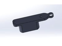
X Carriage Alignment Tool for Geeetech Prusa i3 by DougInAZ
by Thingiverse
Last crawled date: 3 years, 1 month ago
Update 1/15/18 I added a version that might work better in tight spaces. It should be the same height as the shorter one, but it's always best to print a pair; one of the file here, and the other a mirror of that file.
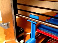
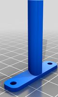
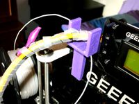
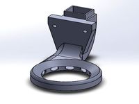
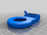
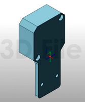
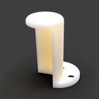
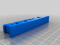
This Thing includes two nearly identical tools and one that should fit tight spaces better. You use a pair of one of them to set the X carriage perpendicular to the threaded rods, and parallel to the horizontal plane of the printer. One tool grips the smooth rod tighter and may be taller. Since I only used the original, I can't comment on the other two.
I made these tools for a family member, but never used them at the time. I forgot about them until I recently had a reason to readjust my X carriage settings.
There are several steps here. If your printer is/was operating normally, start at step A. If you have removed or are replacing the X carriage, start at D and then restart at A.
A. WHEN THE ALIGNMENT GETS DISTURBED DUE TO A CRASH INTO THE BED OR A STEPPER MOTOR THAT DROPS STEPS.
If the carriage is noticeably no longer parallel to the bed, it is probably best to manually adjust one side to get the carriage reasonably close to parallel to the frame of the printer. With the printer power removed, turn the stepper motor coupler(s) Clockwise (as viewing the front of the stepper) to RAISE the Carriage. Turn Counterclockwise to lower the carriage.
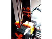
Once it is acceptable, raise the carriage using the computer or firmware adjustment routines to place the alignment tools on the smooth rods. Then lower the carriage so it rests or is close to resting on the tools.
B. FINAL ALIGNMENT OF CARRIAGE
The final step is to adjust each stepper motor shaft to position the X carriage a few thousandths above the stepper motor coupler (the thickness of a piece of printer paper), ensuring that the coupler-spring is not compressed. Probably a good way to do this is to put a piece of paper between the top of the alignment tool and the linear bearing holder. Adjust the stepper motor position manually to lower it down on to paper and stop when the paper is touching the paper, but with minimal pressure. Both sides should get the same treatment, whatever scheme you use. You can raise the carriage using the motors and remove the tools now, or after the next step.
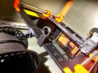
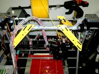
C. PLACING SYNC MARKS ON EACH STEPPER MOTOR COUPLER.
The carriage should now be parallel to the printer frame. The next step will add visual marking to the stepper couplers so that is easy to see if the stepper positions ever get out of sync (and upset the bed leveling).
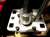
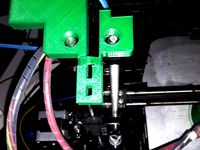
This amounts to nothing more than a mark in the same position on each stepper motor coupler, see photo. Since the carriage is aligned, you can set it in any position for marking both couplers. Remove the tools if they are still present. FWIW, rather than marking, I like to loosen one coupler and position it so it matches the second one.
As you use the printer, the marks should always remain in the same angular position. There is nothing in the printer design that allows the printer to know if they get out of sync. A bad adjustment on a stepper motor driver potentiometer can cause a stepper to occasionally drop steps. YouTube contains videos on the adjustment procedure. All it takes is a voltmeter, a small screw driver, and maybe three hands.
END OF ADJUSTMENT
D. PROCEDURE FOR CARRIAGE INSTALLATION DURING INITIAL ASSEMBLY OR REASSEMBLY.
I haven't done this, and I'm writing this procedure from memory and recalling how clumsy it was as recommended in the build manual. If some steps don't work, please suggest some changes. I'm not likely to build another.
As you are getting ready to install the X carriage assembly, rather than install the threaded rods into the X carriage, set them aside and insert them later. Assemble the X carriage including the smooth rods. Attach the tools to each smooth rod near the bottom.
With the top plates removed, place the X carriage into position and lower the smooth rods into the hole in the frame, with each side of the X carriage resting on an alignment tool.
Loosely attach the top plates, placing the smooth rod through the hole for the smooth rod. With the top plates installed, the carriage will be stable, resting on the tool, which rests on the frame base.
I'm assuming the stepper motors and couplers are attached prior to the above steps, so now, the bottom coupler should be tightened onto the stepper motor shaft, and the upper coupling should be completely loosened to receive the threaded rod.
One at a time, remove the top plates and thread the rod down through the brass nut until it just enters the coupling but does not bottom out. Replace each top plate. Again, it does not have to be tightened, but the threaded rod should be able to be turned by hand with the top plate in place. If it binds, add a drop of oil.
At this point, the X carriage should be in-place, resting on the tools, with the threaded rod resting slightly above the bottom of the coupling cavity.
The next step is to thread the rods, one at a time, down until they just touch the bottom of the cavity, and before they start to lift the carriage more than a few thousandths off the tools. At this point the top coupling can be tightened, tightly!
There is more to do; the final steps will be accomplished, by restarting at step A.
= = = = = = = = = =
INFORMATION YOU CAN LIVE WITHOUT:
When I built my printer, I eventually came to the point where you had to level the bed. At the time I thought that the word level really had nothing to do with what we were doing, but I knew what they meant, and I didn't know a better name for it. What that adjustment does is adjust the printer bed so it is parallel to the X carriage travel (however good or bad that may be). It turns out there is a better word for the procedure and it is TRAMMEL. As a noun, it can be used to refer to a tool for trammeling. As a verb, it refers to making a mechanical alignment or adjustment, which is exactly what carriage/bed leveling is all about. Thanks to GZUMWALT, Thingiverse designer extraordinaire, for introducing me to a new word.
This Thing includes two nearly identical tools and one that should fit tight spaces better. You use a pair of one of them to set the X carriage perpendicular to the threaded rods, and parallel to the horizontal plane of the printer. One tool grips the smooth rod tighter and may be taller. Since I only used the original, I can't comment on the other two.
I made these tools for a family member, but never used them at the time. I forgot about them until I recently had a reason to readjust my X carriage settings.
There are several steps here. If your printer is/was operating normally, start at step A. If you have removed or are replacing the X carriage, start at D and then restart at A.
A. WHEN THE ALIGNMENT GETS DISTURBED DUE TO A CRASH INTO THE BED OR A STEPPER MOTOR THAT DROPS STEPS.
If the carriage is noticeably no longer parallel to the bed, it is probably best to manually adjust one side to get the carriage reasonably close to parallel to the frame of the printer. With the printer power removed, turn the stepper motor coupler(s) Clockwise (as viewing the front of the stepper) to RAISE the Carriage. Turn Counterclockwise to lower the carriage.
Once it is acceptable, raise the carriage using the computer or firmware adjustment routines to place the alignment tools on the smooth rods. Then lower the carriage so it rests or is close to resting on the tools.
B. FINAL ALIGNMENT OF CARRIAGE
The final step is to adjust each stepper motor shaft to position the X carriage a few thousandths above the stepper motor coupler (the thickness of a piece of printer paper), ensuring that the coupler-spring is not compressed. Probably a good way to do this is to put a piece of paper between the top of the alignment tool and the linear bearing holder. Adjust the stepper motor position manually to lower it down on to paper and stop when the paper is touching the paper, but with minimal pressure. Both sides should get the same treatment, whatever scheme you use. You can raise the carriage using the motors and remove the tools now, or after the next step.
C. PLACING SYNC MARKS ON EACH STEPPER MOTOR COUPLER.
The carriage should now be parallel to the printer frame. The next step will add visual marking to the stepper couplers so that is easy to see if the stepper positions ever get out of sync (and upset the bed leveling).
This amounts to nothing more than a mark in the same position on each stepper motor coupler, see photo. Since the carriage is aligned, you can set it in any position for marking both couplers. Remove the tools if they are still present. FWIW, rather than marking, I like to loosen one coupler and position it so it matches the second one.
As you use the printer, the marks should always remain in the same angular position. There is nothing in the printer design that allows the printer to know if they get out of sync. A bad adjustment on a stepper motor driver potentiometer can cause a stepper to occasionally drop steps. YouTube contains videos on the adjustment procedure. All it takes is a voltmeter, a small screw driver, and maybe three hands.
END OF ADJUSTMENT
D. PROCEDURE FOR CARRIAGE INSTALLATION DURING INITIAL ASSEMBLY OR REASSEMBLY.
I haven't done this, and I'm writing this procedure from memory and recalling how clumsy it was as recommended in the build manual. If some steps don't work, please suggest some changes. I'm not likely to build another.
As you are getting ready to install the X carriage assembly, rather than install the threaded rods into the X carriage, set them aside and insert them later. Assemble the X carriage including the smooth rods. Attach the tools to each smooth rod near the bottom.
With the top plates removed, place the X carriage into position and lower the smooth rods into the hole in the frame, with each side of the X carriage resting on an alignment tool.
Loosely attach the top plates, placing the smooth rod through the hole for the smooth rod. With the top plates installed, the carriage will be stable, resting on the tool, which rests on the frame base.
I'm assuming the stepper motors and couplers are attached prior to the above steps, so now, the bottom coupler should be tightened onto the stepper motor shaft, and the upper coupling should be completely loosened to receive the threaded rod.
One at a time, remove the top plates and thread the rod down through the brass nut until it just enters the coupling but does not bottom out. Replace each top plate. Again, it does not have to be tightened, but the threaded rod should be able to be turned by hand with the top plate in place. If it binds, add a drop of oil.
At this point, the X carriage should be in-place, resting on the tools, with the threaded rod resting slightly above the bottom of the coupling cavity.
The next step is to thread the rods, one at a time, down until they just touch the bottom of the cavity, and before they start to lift the carriage more than a few thousandths off the tools. At this point the top coupling can be tightened, tightly!
There is more to do; the final steps will be accomplished, by restarting at step A.
= = = = = = = = = =
INFORMATION YOU CAN LIVE WITHOUT:
When I built my printer, I eventually came to the point where you had to level the bed. At the time I thought that the word level really had nothing to do with what we were doing, but I knew what they meant, and I didn't know a better name for it. What that adjustment does is adjust the printer bed so it is parallel to the X carriage travel (however good or bad that may be). It turns out there is a better word for the procedure and it is TRAMMEL. As a noun, it can be used to refer to a tool for trammeling. As a verb, it refers to making a mechanical alignment or adjustment, which is exactly what carriage/bed leveling is all about. Thanks to GZUMWALT, Thingiverse designer extraordinaire, for introducing me to a new word.
Similar models
thingiverse
free

Parametric Z-axis coupler (stepper and threaded rod coupling) by aspesilorenzo
... / threaded rod coupler.
variable names should be self-explanatory, the default values are meant for a nema17 motor and a m8 rod.
thingiverse
free
Tool to level X-axis of Prusa i3 by mangtronix
... x-axis rod and y-axis rod. then you could hang one of the tools on each side of the x-axis rod and adjust them at the same time.
thingiverse
free

Wanhao i3 X-axis adjustment tool by martin_au
...ate positioning relative to the y-axis rods. probably the most accurate method of aligning the x-axis carriage of these printers.
grabcad
free

5mm to 8mm flexible shaft coupler
...5mm to 8mm flexible shaft coupler
grabcad
used for 3d printers, cnc .
it connects shaft of stepper motor to threaded rod
thingiverse
free

openbuilds Threaded Rod Plate - NEMA 17 Stepper Motor by olo2000pm
...builds threaded rod plate - nema 17 stepper motor by olo2000pm
thingiverse
openbuilds threaded rod plate - nema 17 stepper motor
thingiverse
free
Sidewinder X1 Z sync adjustment kit by Gaston-69
...!
at each z home visually check the turning arrows are facing the fixed ones.
both turning arrows should be parallel at any time.
thingiverse
free

Duplicator i3 Y Axis Skew Correction by dotPhoenix
...a piece of glass or metal z axis braces similar to https://www.thingiverse.com/thing:921948 square with a wide, flat flange such...
grabcad
free

NEMA 11 Stepper Motor
...related projects. i couldn't find a model with a similar length to this one. the top plate is threaded...
thingiverse
free

Anet A8 Adjustable Z Axis Top Plates for Anti Bind & Alignment by Ghostjnr
... to be able to flex because anytime it does it will show in the print.
my a8 is a 2017 model.
please let me know what you think.
thingiverse
free

Shaft Coupler for stepper motor 8mm x 5mm and 8mm x 6.35mm
.... one is 8mm to 5mm and the other one is 8mm to 6.35mm shaft diameters.use 2 x m3 capscrew and nut for each to clamp it to shafts
Douginaz
thingiverse
free
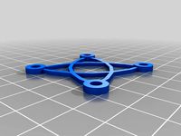
Simple Fan Guard by DougInAZ
...original, but other than that should do about the same job as the original. if you want it thicker, scale it in the z direction.
thingiverse
free

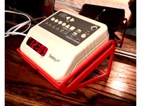
Super Glue Holder by DougInAZ
...se for super glue before i had a 3d printer. now, i find it an essential item to assmeble and patch pla and some other plastics.
thingiverse
free

Soap Tray for Kitchen or bathroom by DougInAZ
...version without drain holes, let me know and i'll add one.
note: the models are sized @ 10x. scale to 0.1 for original size.
thingiverse
free

Nose Clip for anti COVID mask by DougInAZ
...nother version(s) right away.
update 4/17/21 i added a version that fits tighter on my face and is twice as thick in the arms.
thingiverse
free
Holder for X10 Clock by DougInAZ
...the rear feet of the stand. it was really not needed for my use, and probably doesn't need to be used for most applications.
thingiverse
free
Joy Stick Handle for Power Chair by DougInAZ
...meter, with a 11.5 mm circular stop below.
the part has a thin internal brim built into it that has to be removed prior to use.
thingiverse
free
Base for Enermax EAS02S Bluetooth Speaker by DougInAZ
...ne perimeter for the base, and the infill moved the printed thread where they were adjacent. however, it was surprisingly rigid.
thingiverse
free

Tray for Pills, etc. by DougInAZ
...two colors using a y-switching extruder and patched g-code. there is also a small foot. print four and glue them on the bottom.
thingiverse
free

Tether for Drill Chuck Key by DougInAZ
...asy to heat them with a hair dryer and slip them around the 90 deg bend when they were hot. upon cooling, they are a shrink fit.
thingiverse
free

Steering Wheel Spinner Knob for 29x36 mm Wheel by DougInAZ
...ings like this, the question of legality and the risk imposed by having this attached to the steering wheel is borne by the user.
Geeetech
3d_export
free
part right for geeetech acrylic i 3
...part right for geeetech acrylic i 3
3dexport
the engine can be shifted
3d_export
free
cable holder
...cable holder 3dexport for geeetech acrylic i...
thingiverse
free
geeetech a10 by Igor_garbuz
...geeetech a10 by igor_garbuz
thingiverse
model geeetech a10 ( solidworks).
thingiverse
free

geeetech calibration by muffler1979
...geeetech calibration by muffler1979
thingiverse
just a calibration test for the bed on a geeetech
thingiverse
free
Fan for Geeetech proB
...fan for geeetech prob
thingiverse
this is my fan for the geeetech pro b i3.
thingiverse
free

Chain for Geeetech A30
...chain for geeetech a30
thingiverse
this is my personal review of chain for geeetech a30.
thingiverse
free

Zugentlastung Hotend Geeetech A30T / Strain relief Geeetech A30T by 3DDennis1983
...zugentlastung hotend geeetech a30t / strain relief geeetech a30t by 3ddennis1983
thingiverse
zugentlastung hotend geeetech a30t
thingiverse
free
Kettenhalter i3x geeetech by Autark
...kettenhalter i3x geeetech by autark
thingiverse
geeetech i3x
thingiverse
free
Geeetech A10 Fanduct by stefan177gr
...geeetech a10 fanduct by stefan177gr
thingiverse
fanduct for geeetech a10
thingiverse
free
Geeetech filament guide by RicardoZ2018
...geeetech filament guide by ricardoz2018
thingiverse
desing for geeetech i3x
Alignment
3d_export
$5
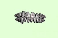
orthodontic aligners
...aligners are plastic replicas of your teeth. wearing them puts gentle pressure on the teeth, ever-so-slightly repositioning them.
3d_export
$15
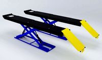
Wheel Alignment Lifts 3D Model
...heel alignment lifts
wheel alignment lifts 3d model download .c4d .max .obj .fbx .ma .lwo .3ds .3dm .stl poothian 108990 3dexport
3d_export
$99

Alignment Systems
...dimensions. -ideal for your auto service project. -scene for 3ds max 2012 and v-ray 2.0 !!!in file only 3d model without light!!!
turbosquid
$85

Film laser alignment cutting machine
...ng machine for download as 3ds, max, ige, obj, fbx, and sldas on turbosquid: 3d models for games, architecture, videos. (1423482)
3d_export
$159
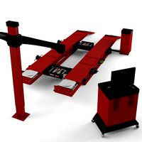
Alignment Systems with Car Lift
...dimensions. -ideal for your auto service project. -scene for 3ds max 2012 and v-ray 2.0 !!!in file only 3d model without light!!!
3d_export
$15

modular rpg game environment - low poly - pbr - gameready
...aligned). textures folder(all pbr textures) other formats modular pieces (dae obj stl fbx ) modular environment (dae obj stl fbx)
3d_export
$5

bookshelf
...g unit a well-thought-out and solid look. the shelves align perfectly with the frame to create a strong and uniform expression.
3d_ocean
$4
The Engineer
... to model: front view back view side view / both left and right with and without arm composite psd file of all views each imag...
3d_ocean
$25

Stationary Presentation Kit
...st to the biggest, all beautifully aligned and positioned and ready to render. here’s what the scene contains: 1. single-fold ...
vizpark
$15

HDRI Skydome 30
...images were manually adjusted and corrected with dust removal, alignment and chromatic abberation...
Carriage
archibase_planet
free

Carriage
...arriage
archibase planet
perambulator baby carriage pram
carriage n250908 - 3d model (*.gsm+*.3ds) for interior 3d visualization.
3d_export
free
carriage
...carriage
3dexport
old fashion carriage model, more files here:
turbosquid
$140

Carriage
...urbosquid
royalty free 3d model carriage for download as max on turbosquid: 3d models for games, architecture, videos. (1482052)
turbosquid
$25

Carriage
...urbosquid
royalty free 3d model carriage for download as max on turbosquid: 3d models for games, architecture, videos. (1285944)
3d_export
free
carriage
...carriage
3dexport
game cart
3d_ocean
$15

Barrel Carriage
...ieval oak old transport wheels wine wood
this model contains a barrel and a carriage. it is a medieval type of wood oak carriage.
turbosquid
$40
Carriage
...ty free 3d model carriage for download as obj, fbx, and blend on turbosquid: 3d models for games, architecture, videos. (1290094)
turbosquid
free

Carriage
...yalty free 3d model carriage for download as ma, obj, and fbx on turbosquid: 3d models for games, architecture, videos. (1239157)
3d_export
$5

Medieval carriage
...medieval carriage
3dexport
medieval carriage in fairy style
turbosquid
$58

Carriage
...d model carriage with scene for download as max, obj, and fbx on turbosquid: 3d models for games, architecture, videos. (1276262)
I3
3d_export
$10

suv i3
...suv i3
3dexport
suv i3 2013 series
3d_ocean
$89

BMW i3 2012
...y, in real units of measurement, qualitatively and maximally close to the original. model formats: - *.max (3ds max 2008 scanl...
cg_studio
$99

BMW i3 20143d model
...
cgstudio
.3ds .c4d .fbx .lwo .max .obj - bmw i3 2014 3d model, royalty free license available, instant download after purchase.
cg_studio
$99

BMW i3 20123d model
...tudio
.3ds .c4d .fbx .lwo .max .mb .obj - bmw i3 2012 3d model, royalty free license available, instant download after purchase.
cg_studio
$99

BMW i3 20143d model
...tudio
.3ds .c4d .fbx .lwo .max .mb .obj - bmw i3 2014 3d model, royalty free license available, instant download after purchase.
humster3d
$75

3D model of BMW i3 2014
...
buy a detailed 3d model of bmw i3 2014 in various file formats. all our 3d models were created maximally close to the original.
humster3d
$40

3D model of Kitchen Set I3
...uy a detailed 3d model of kitchen set i3 in various file formats. all our 3d models were created maximally close to the original.
3d_ocean
$30

Kitchen set i3
...ensils oven plates shelves sink table ware
kitchen set i3 include 3d models: cooker, oven, sink, cupboards, table, chair, plates.
3d_ocean
$89

BMW i3 2014
...y, in real units of measurement, qualitatively and maximally close to the original. model formats: - *.max (3ds max 2008 scanl...
cg_studio
$99

BMW i3 Concept 20113d model
...i3
.3ds .c4d .fbx .lwo .max .obj - bmw i3 concept 2011 3d model, royalty free license available, instant download after purchase.
Prusa
turbosquid
$2
Frame Filament Guide Clip-On for Prusa Mk3
...rame filament guide clip-on for prusa mk3 for download as stl on turbosquid: 3d models for games, architecture, videos. (1634730)
3d_export
free
prusa i3 mk3s laser mount for opt lasers
...to learn more about the blue laser technology that conceived the cutting and engraving laser heads from opt lasers, please visit:
turbosquid
free
Prusa small printer adapter holder
...er for download as ipt, skp, dwg, dxf, fbx, ige, obj, and stl on turbosquid: 3d models for games, architecture, videos. (1642936)
3d_export
$30

geisha by jonathan adler
...** i did a 3d printing test in the prusa software, you can find it among the attached images.<br>exchange:<br>.blend...
thingiverse
free

Prusa without Prusa (rc2) by madless
...prusa without prusa (rc2) by madless
thingiverse
just the main part of prusa rc2 faceshield, without writing.
enjoy :)
thingiverse
free
Prusa by acejbc
...prusa by acejbc
thingiverse
prusa knob info
m3 8mm screw
thingiverse
free

Prusa house
...prusa house
thingiverse
how prusa house could look like...
thingiverse
free

Prusa Mk2 "Fake Prusa" LCD cover by anraf1001
...r by anraf1001
thingiverse
version of prusa's lcd cover with "fake prusa" instead of "original prusa"
thingiverse
free
Prusa stabilizator by gutiueugen
...prusa stabilizator by gutiueugen
thingiverse
prusa stabilizator
thingiverse
free
Keychain Prusa by rbarbalho
...keychain prusa by rbarbalho
thingiverse
keychain with text prusa.
Tool
turbosquid
$21

Tool box with tools
... available on turbo squid, the world's leading provider of digital 3d models for visualization, films, television, and games.
archibase_planet
free
Tools
...tools
archibase planet
tools instruments implements
tools n070114 - 3d model (*.gsm+*.3ds+*.max) for interior 3d visualization.
3d_ocean
$12
Tools
...tools
3docean
hammer metal old screw tools wrench
maya
turbosquid
$6

Tool Cart / Tool Box
...
royalty free 3d model tool cart / tool box for download as on turbosquid: 3d models for games, architecture, videos. (1241859)
3d_ocean
$15

crimp tool
... tool copper cutter crimp crimp tool electrical electrical tools press tools pressing tool tools wire cutter
created in maya 2013
3d_ocean
$5

Tools
...tools
3docean
3d models paint tools work
3d,models,works,paint,art,create,working,
3d_export
free

tools
...tools
3dexport
coldsteel
turbosquid
$15

Tools
...turbosquid
royalty free 3d model tools for download as blend on turbosquid: 3d models for games, architecture, videos. (1331352)
3ddd
$1

bar tool
...bar tool
3ddd
барный
bar tool
turbosquid
$35

tools
... available on turbo squid, the world's leading provider of digital 3d models for visualization, films, television, and games.