Thingiverse

Woodstock Delta Printer by jpickens
by Thingiverse
Last crawled date: 3 years, 1 month ago
I have been building derivative Rostock Delta printers based upon Johann's excellent design for several years. My current version, which uses magnetic ball joint arms, is derived from the original Johann Rostock, as well as several other designs posted here on Thingiverse.
Here's a Youtube video of it in action:https://youtu.be/jT24ClLlQKo
This design uses a direct drive extruder, the Titan by E3D. When they released this product, I realized that this geared extruder with a pancake stepper motor was just what I needed to chuck the bowden extruder in the bin and mount it directly on the end effector.
The whole effector with the extruder drive and E3D hotend weighs under 300grams.
Since I have modified many of these parts, I thought it would be helpful to gather up the pieces in one place to assist others in making their own Woodstock Delta Printer!
While the base stucture is exactly like the original Johann Rostock, with 8mm smooth rods placed in pairs 60mm apart, and using 250mm diagonal rods, the frame is a bit shorter. I took the wood panel laser cut design from:
http://www.thingiverse.com/thing:34570
by Docmooney
Even though Docmooney posted his DXF drawings of the wood panels with two thicknesses shown in the names, I used 12mm (1/2" nominal) baltic birch plywood for all of the pieces. They consist of a base panel, a top panel, two sides, and a short front center base support piece, 5 pieces in all. By using laser cut plywood, an extremely precise and square frame can be made, which is crucial in building a successful delta printer.
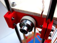
Besides the frame, 3D printed parts make up the rest of the dimensionally important build. We have three vertical towers, X,Y, and Z each having the two smooth 8mm steel rods held in place by three fixed printed parts. These are the lower stepper motor holder, the upper endstop holder, and the topmost boxed idler bearing block with 608zz skate bearings for the GT2 drive belt.
I used Johann's original design for the stepper motor holder and upper endstop.
My design uses six 30 inch (762mm) hardened steel 8mm rods which extend above the top panel of the wood frame. These extensions are used to hold the boxed idler which performs two functions:
Mounting the idler above the frame allows the belts to be tensioned by loosening the clamp bolts on the rods, and pushing up on the boxed idler.
The idler sitting above the endstop forms a sort of truss for the smooth rods, which stiffens them and dampens vibrations, improving performance of the printer.
The boxed idler comes from:
Chowderhead
Which was remixed from Johann:http://www.thingiverse.com/thing:19903
Now to the fun part where I start really tweaking things.
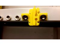
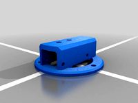
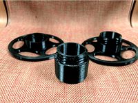
My moving carriages use Igus polymer bearings for quiet operation.
I used printed u-joints for my original version of this printer, but they are sloppy.
Wanted to go with zero backlash magnetic ball end diagonal arms, so I modified a
SCAD file from this thing:http://www.thingiverse.com/thing:303637
by Kolergy
I really hacked up the original, moving the spacing of the magnets to 60mm, in line with the smooth rods, changed to 12mm magnets, and changed the drive belt grooves to GT2 belts. I also made two sections of grooves with a gap in between to act as your belt coupler, so you can save money and cut your own belts instead of ordering closed loop. I used this to get the GT2 belt profile:
http://www.thingiverse.com/thing:194554
by alj_rprp
I'm pretty hacky with the nice SCAD coding, so my additions aren't too elegant, but they work. I'm including both the SCAD versions as modified by me, and the STL files for printing.
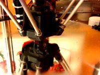
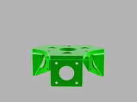
Next, we have to have a moving triangular effector to hold the extruder and hotend.
I modified this thing:
http://www.thingiverse.com/thing:93042
By Aeropic
The mods were to get the magnets to the 60mm spacing, and to open up the center to allow the Titan extruder to fit. Unfortunately, due to the size constraints, the hot end tip is approx. 20mm off center, which isn't ideal, but it prints just fine.
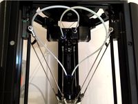
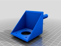
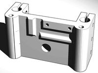
I worked up a design to hold the Titan extruder based upon:
http://www.thingiverse.com/thing:1958993
by bfesser
Again, I hacked it up pretty good, and added an extension for a strain relief 1/4" plastic hose to support and attach the wiring harness from the frame to the effector.
Just add the normal assortment of stepper motors, GT2 belts, GT2-20 tooth drive gears, heated bed (260mm Alu-MK3 bed), the Titan Extruder, E3D hotend, 12V 30A power supply, and off you go!
I'll be adding more photos, and a complete parts list as soon as I can.
Let me know what you think!
Update 3-10-2017:
Just uploaded a new version of the E3D Titan extruder mount.
This one has Holes in the name, and has all necessary mounting holes included.
It has a hex shaped recess in the side for attaching two M3 nuts, one to clamp down
The mount, with the second threaded on higher to hold the tensioning string.
Here's a Youtube video of it in action:https://youtu.be/jT24ClLlQKo
This design uses a direct drive extruder, the Titan by E3D. When they released this product, I realized that this geared extruder with a pancake stepper motor was just what I needed to chuck the bowden extruder in the bin and mount it directly on the end effector.
The whole effector with the extruder drive and E3D hotend weighs under 300grams.
Since I have modified many of these parts, I thought it would be helpful to gather up the pieces in one place to assist others in making their own Woodstock Delta Printer!
While the base stucture is exactly like the original Johann Rostock, with 8mm smooth rods placed in pairs 60mm apart, and using 250mm diagonal rods, the frame is a bit shorter. I took the wood panel laser cut design from:
http://www.thingiverse.com/thing:34570
by Docmooney
Even though Docmooney posted his DXF drawings of the wood panels with two thicknesses shown in the names, I used 12mm (1/2" nominal) baltic birch plywood for all of the pieces. They consist of a base panel, a top panel, two sides, and a short front center base support piece, 5 pieces in all. By using laser cut plywood, an extremely precise and square frame can be made, which is crucial in building a successful delta printer.
Besides the frame, 3D printed parts make up the rest of the dimensionally important build. We have three vertical towers, X,Y, and Z each having the two smooth 8mm steel rods held in place by three fixed printed parts. These are the lower stepper motor holder, the upper endstop holder, and the topmost boxed idler bearing block with 608zz skate bearings for the GT2 drive belt.
I used Johann's original design for the stepper motor holder and upper endstop.
My design uses six 30 inch (762mm) hardened steel 8mm rods which extend above the top panel of the wood frame. These extensions are used to hold the boxed idler which performs two functions:
Mounting the idler above the frame allows the belts to be tensioned by loosening the clamp bolts on the rods, and pushing up on the boxed idler.
The idler sitting above the endstop forms a sort of truss for the smooth rods, which stiffens them and dampens vibrations, improving performance of the printer.
The boxed idler comes from:
Chowderhead
Which was remixed from Johann:http://www.thingiverse.com/thing:19903
Now to the fun part where I start really tweaking things.
My moving carriages use Igus polymer bearings for quiet operation.
I used printed u-joints for my original version of this printer, but they are sloppy.
Wanted to go with zero backlash magnetic ball end diagonal arms, so I modified a
SCAD file from this thing:http://www.thingiverse.com/thing:303637
by Kolergy
I really hacked up the original, moving the spacing of the magnets to 60mm, in line with the smooth rods, changed to 12mm magnets, and changed the drive belt grooves to GT2 belts. I also made two sections of grooves with a gap in between to act as your belt coupler, so you can save money and cut your own belts instead of ordering closed loop. I used this to get the GT2 belt profile:
http://www.thingiverse.com/thing:194554
by alj_rprp
I'm pretty hacky with the nice SCAD coding, so my additions aren't too elegant, but they work. I'm including both the SCAD versions as modified by me, and the STL files for printing.
Next, we have to have a moving triangular effector to hold the extruder and hotend.
I modified this thing:
http://www.thingiverse.com/thing:93042
By Aeropic
The mods were to get the magnets to the 60mm spacing, and to open up the center to allow the Titan extruder to fit. Unfortunately, due to the size constraints, the hot end tip is approx. 20mm off center, which isn't ideal, but it prints just fine.
I worked up a design to hold the Titan extruder based upon:
http://www.thingiverse.com/thing:1958993
by bfesser
Again, I hacked it up pretty good, and added an extension for a strain relief 1/4" plastic hose to support and attach the wiring harness from the frame to the effector.
Just add the normal assortment of stepper motors, GT2 belts, GT2-20 tooth drive gears, heated bed (260mm Alu-MK3 bed), the Titan Extruder, E3D hotend, 12V 30A power supply, and off you go!
I'll be adding more photos, and a complete parts list as soon as I can.
Let me know what you think!
Update 3-10-2017:
Just uploaded a new version of the E3D Titan extruder mount.
This one has Holes in the name, and has all necessary mounting holes included.
It has a hex shaped recess in the side for attaching two M3 nuts, one to clamp down
The mount, with the second threaded on higher to hold the tensioning string.
Similar models
thingiverse
free
Idler end for Rostock by Johann
...op) and a plywood board.
newer versions of the openscad source files will be published here: https://github.com/jcrocholl/rostock
thingiverse
free

MS-Delta Frame by Spaceman9105
...d. it will have an outo bed leveling function and rods will be connected with magnets. https://www.thingiverse.com/thing:2938171
thingiverse
free
Magnetic carriage Linear rail by alex_des
...giverse.com/thing:2151380
magnetic carriage for delta printer, 15x5 magnets, 23x24 linear rail mount. gt2 belt lock. endstop pin.
thingiverse
free
Delta effector with magnetic joints and fans by cla
...ng the printed filament.
2014_05_11 i uploaded r1 stl. i found an error in proe regeneration.
the distance between rods is 42mm
thingiverse
free
Dual Extruder Delta Printer by Xlemos
...rored in the your slicer software.
to mount the two spools take a look at this design, https://www.thingiverse.com/thing:2587079.
thingiverse
free
E3D Titan sextruder (Hanging extruder) by Xielous
...ove the effector in delta style printers. it takes load off of the effector while still remaining relatively close to the hotend.
thingiverse
free

Delta Effector w. Magnetic joints for E3D V6 by robkar
...d-looking, and with magnetic joints for minimal backlash.
here is the complete printer: http://www.thingiverse.com/thing:923830
thingiverse
free
QU-BD MBE extruder modifications for Rostock Delta Printer by harmane
...ration of the hotend from the stepper drive with 2 printed components. parts were printed on an up mini with.25mm layer thickness
thingiverse
free
Three Way Nema17 Flying Extruder mount for E3D Titan by aussiephil
...nter.
two high resolution stl's are provide
48mm can be used for all motors up to 48mm
40mm for motos 40mm or less in length.
thingiverse
free
Rostock Mechanical Endstop Idler by ryonsherman
...rostock mechanical endstop idler by ryonsherman
thingiverse
a belt idler end with mechanical endstop mount for rostock.
Jpickens
thingiverse
free
Small Spool Extension Coupler by jpickens
...tension.
you just print it and thread the coupler extension in between the halves, and viola', the spool is now twice as big!
thingiverse
free
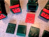
Bigger Die For Butterpig by jpickens
... make sure the original baconlicious remix decorate .scad file is in the same folder as the decorate_big.scad file is.
have fun!!
thingiverse
free
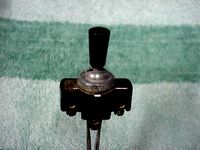
Early VW Microbus Semaphore Switch Knob by jpickens
... to improve it.
photo courtesy of everett barnes from thesamba.comhttp://www.thesamba.com/vw/forum/album_page.php?pic_id=195233
thingiverse
free

Rostock Micro Extruder Mount by jpickens
...sing this same lightweight stepper, as the mount locations are set by the motor, and not the particular extruder you want to use.
thingiverse
free

Eora 3D Scanner Calibration Target Stand by jpickens
... printer to not make the fit too tight. mine fit just right.
print with the triangular end on the bed, slot oriented vertically.
thingiverse
free
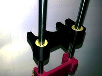
16mm Sleeve Carriage for Rostock Printer and Igus Linear Bearings by jpickens
...m rods, and hope to use these simple and cheap bearings instead of the loud and expensive metal ones. we'll see how it goes.
thingiverse
free

Orbiter Extruder Mount for E3D Toolchanger by jpickens
...re for mounting the orbiter body, and are sized for 3mm inner diameter, and must be tapped for the 3mm mounting bolts in the kit.
thingiverse
free

Happy Face Powered Face Mask by jpickens
...lled into the holes in the intake cylinder to mount it in place.
video of happy face mask in action:
https://youtu.be/bpcbwspdacm
thingiverse
free
Google Pixel 3a xl Folding Case
...thingiverse this here's a remix of gabesh's remix of jpickens case. printed in tpu, gabesh's case will nest inside...
Woodstock
design_connected
$16

Woodstock
...woodstock
designconnected
mio woodstock computer generated 3d model.
design_connected
$9

Woodstock
...woodstock
designconnected
poliform woodstock computer generated 3d model. designed by massaud, jean-marie.
turbosquid
$39

Woodstock Wardrobe
... available on turbo squid, the world's leading provider of digital 3d models for visualization, films, television, and games.
turbosquid
$15

Woodstock End Table
... available on turbo squid, the world's leading provider of digital 3d models for visualization, films, television, and games.
3ddd
$1
Hudson Valley Lighting 7509-SN Woodstock 1 Light Flush Mounts
...tock 1 light flush mounts
артикул: 7509-sn
материал: satin nickel
остальное здесь:http://www.hudsonvalleylighting.com/
3d_export
$19
Coffee table Woodstock square
... x 31.53" x 17.7"<br>- model parts: 3<br>- material count: 1<br>- xform: yes<br>- boxtrick: yes
3d_export
$19
Coffee table Woodstock rectangle
...x 23.53" x 18.49"<br>- model parts: 3<br>- material count: 1<br>- xform: yes<br>- boxtrick: yes
3ddd
$1

Euphoria / Paola navone
...monocoque qui est né de l'idée de l'utilisation de woodstock ®, un matériau couramment utilisé dans l'industrie automobile -...
thingiverse
free

Woodstock stencil
...woodstock stencil
thingiverse
woodstock stencil
thingiverse
free

Peanuts - Woodstock
...peanuts - woodstock
thingiverse
childhood memories...
Delta
design_connected
$16

Delta
...delta
designconnected
lj lamps delta computer generated 3d model. designed by janowski-lenhart, sasha.
design_connected
$16
Delta
...delta
designconnected
arflex international spa delta computer generated 3d model. designed by koivisto, eero.
design_connected
$13
Delta
...delta
designconnected
emu group delta armchairs computer generated 3d model. designed by marin chiaramonte .
3ddd
$1
Delta Light
...delta light
3ddd
delta light , you-turn reo 3033
точечний светильник delta light
3ddd
$1
Blanco / delta
...blanco / delta
3ddd
blanco , мойка
мойка blanco delta со смесителем
3ddd
$1
Delta Light Spot
...delta light spot
3ddd
delta light
светильник фирмы delta light
3ddd
free

Bianchi Delta LVMDLT200100
...i delta lvmdlt200100
3ddd
bianchi delta , смеситель
смеситель bianchi delta lvmdlt200100
design_connected
free

Delta 190
...delta 190
designconnected
free 3d model of delta 190 by zanotta designed by progetti, emaf.
design_connected
$27
Delta 211
...delta 211
designconnected
zanotta delta 211 computer generated 3d model. designed by progetti, emaf.
design_connected
$27

Delta 234
...delta 234
designconnected
zanotta delta 234 computer generated 3d model. designed by progetti, emaf.
Printer
archibase_planet
free
Printer
...inter
archibase planet
printer laser printer pc equipment
printer n120614 - 3d model (*.gsm+*.3ds) for interior 3d visualization.
archibase_planet
free
Printer
...rchibase planet
laser printer office equipment computer equipment
printer - 3d model (*.gsm+*.3ds) for interior 3d visualization.
turbosquid
$100
Printer
...er
turbosquid
royalty free 3d model printer for download as on turbosquid: 3d models for games, architecture, videos. (1487819)
turbosquid
$3
Printer
...turbosquid
royalty free 3d model printer for download as max on turbosquid: 3d models for games, architecture, videos. (1670230)
turbosquid
$1
printer
...turbosquid
royalty free 3d model printer for download as max on turbosquid: 3d models for games, architecture, videos. (1595546)
turbosquid
$1
printer
...turbosquid
royalty free 3d model printer for download as max on turbosquid: 3d models for games, architecture, videos. (1595105)
turbosquid
$10
Printer
...id
royalty free 3d model printer for download as max and 3dm on turbosquid: 3d models for games, architecture, videos. (1607146)
turbosquid
$7
Printer
...royalty free 3d model printer for download as ma, ma, and obj on turbosquid: 3d models for games, architecture, videos. (1644580)
turbosquid
$30
Printer
... available on turbo squid, the world's leading provider of digital 3d models for visualization, films, television, and games.
turbosquid
$20
Printer
... available on turbo squid, the world's leading provider of digital 3d models for visualization, films, television, and games.