Thingiverse
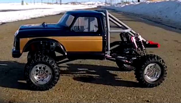
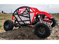
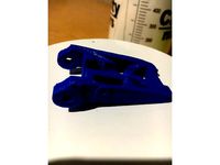
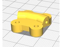
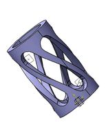
WLToys 12428 Crawler Conversion Chassis Parts
by Thingiverse
Last crawled date: 4 years, 2 months ago
Hi guys,
As we used to say in the software world, this is version one point uh oh. I've got the truck all put together (several times) and everything works fine but I don't expect that it's bullet proof yet. The gearbox dust cover is coming soon so hold off printing if that freaks you out.
Check out the project on YouTube: https://www.youtube.com/watch?v=pi2Jhd1oP-0
Like and subscribe if you dig it. This stuff takes a lot of work and some feedback is greatly appreciated (positive or negative). I'm thinking about doing an actual build tutorial video but part of me thinks that's a waste of time because anybody printing this thing probably knows enough to build a crawler. Crawler are easy, right? Let me know if you think I'm being too optimistic.
I was pretty down on the durability of 3D printed RC car parts but I recently discovered that good PLA printed good and hot actually makes pretty strong parts. Sadly, it's hard to tell if you've got good PLA and good settings without major testing. Seriously, I've had parts break stupidly easy that work great printed from a different spool of plastic, same brand, with the same print settings. It's annoying. Feel free to share you experiences on the YouTube videos so that maybe other people can benefit from it because building your own RC cars is super fun if they perform even close to well.
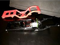
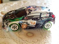
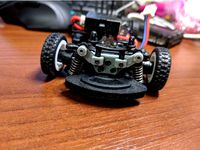
This is the set of chassis parts that goes with the solid front axle I made to convert the WLToys 12428 into a rock crawler. I modeled this stuff to work with cheap Chinese frame rails that are based on the Axial SCX10 II, so a lot of SCX10 parts will likely be useful in some way but I don't have an SCX10 so you're on your own as far as that goes. I also bought some cheap suspension links because I got tired of screwing around with DIY ones, so you can decide what you want to do on your own.
Notes:
The WLToys doesn't have servo reversing so you'll need to go with similar placement to what I ended up doing even if you want to try something different (I tried a few different positions).
The front body mount is set up for the holes that were ALREADY in the body that I used for this project, so you may want to adjust that before you put holes in a new body shell.
I believe the spacing of the holes in the bumper mounts (43mm) is standard but I'm not 100% sure, so drop me a line if you know better.
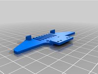
I made a front bumper mount that doubles as a mount point for one side of the servo which only applies if you are using the smaller standard 12428 servo not a proper standard sized heavy duty crawler servo. I'll be doing a mod at some point to convert to standard electronics so a servo mount will come along at that time.
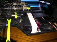
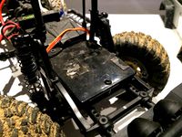
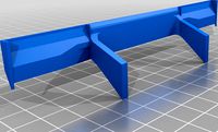
The battery tray, ESC tray and mount are just some quick and dirty parts to get up and running. They seem to work fine for using the WLToys parts but there's a reason axial crammed the servo between the shock mounts so the electronics layout will also change some when I mod this for standard electronics (or you mod yours).
The rear body mount is just a kludge to get everything sitting the way I want it. I drilled holes in the floorboards to mount it and added foam to get the body up a bit higher. You'll need to adjust it to suit what you're doing or come up with something on your own.
The back half that I modeled is mounted to the frame, not the body shell.
The rear shock mounts clamp around that back axle and are far from bullet proof at this point. That's because I haven't decided how I want that to work yet. You may want to adjust them as you see fit. They do work, but you'll need to add something sticky or gritty to keep them from turning on the axle.
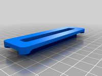
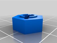
The shock spacer and chassis nut are just handy parts to adjust the way things get mounted. The "nut" just slides into the slot in the rail behind whatever hole you're using to mount something. The hole is M2.5.
The holes in the skid plate/gearbox are M3 except the bearing caps which I believe are M2.5. If you buy suspension links, the rod ends have M3 holes. The bumper mounts and cross brace type parts are also M3 holes. Most everything that mounts to something else is M2.5 holes. I'll be doing a BOM at some point, but I haven't gotten to it yet so for now you're on your own.
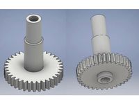
Driveshaft_Front.stl is for use extending the stock 12428 driveshaft for use on the front of the crawler. Just unscrew the plastic piece from stock and replace with this.
Driveshaft_Rear.stl is for use with a metal driveshaft with a ball and pin slider (it's like a dog bone end and goes into the drive shaft with slots cut for travel forward and back) and is the proper length to use on the rear (rear is longer). It needs needs a couple of M2 x 6mm screws to hold it onto the driveshaft (you'll need to drill holes).
Banggood screws that I used: https://www.banggood.com/300pcs-M2-M2_5-M3-Stainless-Steel-Socket-Cap-Screws-Assortment-Kit-p-1062556.html?rmmds=myorder&cur_warehouse=CN
I printed most of this stuff at 0.15mm with 1.2mm walls and heavy infill but the roll of plastic I was using was really, really crappy so I don't want to give to much advice other than to say pay attention to orientation for ease of printing and to use settings that give you nice strong parts. Nothing gave me any trouble despite using crappy plastic, so if you're struggling with a part, have a look and see if some other orientation would work better.
The dust cover for the gearbox isn't quite done yet but I don't expect it to need any additional holes. If that freaks you out, maybe hold off printing until I upload it. The truck is 100% runable with the parts as they sit.
As always, use at your own risk.
Drive to wrench or wrench to drive?
As we used to say in the software world, this is version one point uh oh. I've got the truck all put together (several times) and everything works fine but I don't expect that it's bullet proof yet. The gearbox dust cover is coming soon so hold off printing if that freaks you out.
Check out the project on YouTube: https://www.youtube.com/watch?v=pi2Jhd1oP-0
Like and subscribe if you dig it. This stuff takes a lot of work and some feedback is greatly appreciated (positive or negative). I'm thinking about doing an actual build tutorial video but part of me thinks that's a waste of time because anybody printing this thing probably knows enough to build a crawler. Crawler are easy, right? Let me know if you think I'm being too optimistic.
I was pretty down on the durability of 3D printed RC car parts but I recently discovered that good PLA printed good and hot actually makes pretty strong parts. Sadly, it's hard to tell if you've got good PLA and good settings without major testing. Seriously, I've had parts break stupidly easy that work great printed from a different spool of plastic, same brand, with the same print settings. It's annoying. Feel free to share you experiences on the YouTube videos so that maybe other people can benefit from it because building your own RC cars is super fun if they perform even close to well.
This is the set of chassis parts that goes with the solid front axle I made to convert the WLToys 12428 into a rock crawler. I modeled this stuff to work with cheap Chinese frame rails that are based on the Axial SCX10 II, so a lot of SCX10 parts will likely be useful in some way but I don't have an SCX10 so you're on your own as far as that goes. I also bought some cheap suspension links because I got tired of screwing around with DIY ones, so you can decide what you want to do on your own.
Notes:
The WLToys doesn't have servo reversing so you'll need to go with similar placement to what I ended up doing even if you want to try something different (I tried a few different positions).
The front body mount is set up for the holes that were ALREADY in the body that I used for this project, so you may want to adjust that before you put holes in a new body shell.
I believe the spacing of the holes in the bumper mounts (43mm) is standard but I'm not 100% sure, so drop me a line if you know better.
I made a front bumper mount that doubles as a mount point for one side of the servo which only applies if you are using the smaller standard 12428 servo not a proper standard sized heavy duty crawler servo. I'll be doing a mod at some point to convert to standard electronics so a servo mount will come along at that time.
The battery tray, ESC tray and mount are just some quick and dirty parts to get up and running. They seem to work fine for using the WLToys parts but there's a reason axial crammed the servo between the shock mounts so the electronics layout will also change some when I mod this for standard electronics (or you mod yours).
The rear body mount is just a kludge to get everything sitting the way I want it. I drilled holes in the floorboards to mount it and added foam to get the body up a bit higher. You'll need to adjust it to suit what you're doing or come up with something on your own.
The back half that I modeled is mounted to the frame, not the body shell.
The rear shock mounts clamp around that back axle and are far from bullet proof at this point. That's because I haven't decided how I want that to work yet. You may want to adjust them as you see fit. They do work, but you'll need to add something sticky or gritty to keep them from turning on the axle.
The shock spacer and chassis nut are just handy parts to adjust the way things get mounted. The "nut" just slides into the slot in the rail behind whatever hole you're using to mount something. The hole is M2.5.
The holes in the skid plate/gearbox are M3 except the bearing caps which I believe are M2.5. If you buy suspension links, the rod ends have M3 holes. The bumper mounts and cross brace type parts are also M3 holes. Most everything that mounts to something else is M2.5 holes. I'll be doing a BOM at some point, but I haven't gotten to it yet so for now you're on your own.
Driveshaft_Front.stl is for use extending the stock 12428 driveshaft for use on the front of the crawler. Just unscrew the plastic piece from stock and replace with this.
Driveshaft_Rear.stl is for use with a metal driveshaft with a ball and pin slider (it's like a dog bone end and goes into the drive shaft with slots cut for travel forward and back) and is the proper length to use on the rear (rear is longer). It needs needs a couple of M2 x 6mm screws to hold it onto the driveshaft (you'll need to drill holes).
Banggood screws that I used: https://www.banggood.com/300pcs-M2-M2_5-M3-Stainless-Steel-Socket-Cap-Screws-Assortment-Kit-p-1062556.html?rmmds=myorder&cur_warehouse=CN
I printed most of this stuff at 0.15mm with 1.2mm walls and heavy infill but the roll of plastic I was using was really, really crappy so I don't want to give to much advice other than to say pay attention to orientation for ease of printing and to use settings that give you nice strong parts. Nothing gave me any trouble despite using crappy plastic, so if you're struggling with a part, have a look and see if some other orientation would work better.
The dust cover for the gearbox isn't quite done yet but I don't expect it to need any additional holes. If that freaks you out, maybe hold off printing until I upload it. The truck is 100% runable with the parts as they sit.
As always, use at your own risk.
Drive to wrench or wrench to drive?
Similar models
thingiverse
free

WLToys 12428 Crawler Conversion Push Bumper (Fits SCX10 Clone) by WrenchToDrive
...y, add some hot glue to the joints between the mount and the push bars.
use at your own risk.
wrench to drive or drive to wrench?
thingiverse
free

WLToys 12428 Front Shock Mount for Fall Guy Crawler Truck
...awler-gd/401781070587?hash=item5d8c049afb:g:hj0aaoswgq5cljy7
as always, use at your own risk.
wrench to drive or drive to wrench?
thingiverse
free
12428 SCX10 Clone Jeep Wrangler Parts by WrenchToDrive
...slands driver i run with this:https://www.thingiverse.com/thing:3533920
use at your own risk.
wrench to drive or drive to wrench?
thingiverse
free

WLToys 12428 Solid Front Axle
... out on youtube: https://www.youtube.com/watch?v=pi2jhd1op-0
as always, use at your own risk.
wrench to drive or drive to wrench?
thingiverse
free
WLToys 12428 - 20KG Servo Bracket
...l self tap into the bracket and hold well if your print is accurate. or just use longer screws and nuts for a more reliable hold.
thingiverse
free

WLtoys 12428 Servo Holder for EMAX ES08MA II
...o laying around so i put it to use, not sure how durable it will be in this size of a vehicle but ran it once and so far so good.
thingiverse
free
micro crawler frame losi wltoys redcat etc by Zerwiz
...hingiverse.com/thing:690366https://www.thingiverse.com/thing:2762001https://www.thingiverse.com/thing:2845738
tell me improvments
thingiverse
free
W2D IV - Baja Racer by WrenchToDrive
...use the parts from a wltoys 12428 or something similar pretty easily with your biggest problem being mounting the...
thingiverse
free
Chassis mount for Steering Servo SCX10 Chassis by MrCadillacsts
... be necessary), have fun!!!!
use pla or abs for printing (standard settings)
ps: the wheels are also available on youmagine.com
thingiverse
free
wltoys 12428 body Upgrade, back light
...wltoys 12428 body upgrade, back light
thingiverse
as in the description. i hope it will be useful to you.
12428
3d_export
$6

Figure of a sniper with SVD stl
...set contains only stl format without rig and animations.<br>vertices 12428 polygons...
3d_export
$12

Mini System 3ds obj 3D Model
...3ds obj mini system 3ds obj 3d model koneck 12428 ...
3d_export
$6
Figure of a standing sniper with SVD stl
...set contains only stl format without rig and animations.<br>vertices 12428 polygons...
3d_export
$6

Figure of a sniper in a lying down with SVD stl
...set contains only stl format without rig and animations.<br>vertices 12428 polygons...
thingiverse
free

Wltoys 12428 Bumper protection by Afterhender
...wltoys 12428 bumper protection by afterhender
thingiverse
bumper protection for wltoys 12428
thingiverse
free

12428 Front shock tower by KKFatso
...ont shock tower by kkfatso
thingiverse
to position the 12428 rc car's front shocks upright i have designed a tower for that.
thingiverse
free
wltoys 12428 Front swing arm by DominikWachow
...wltoys 12428 front swing arm by dominikwachow
thingiverse
wltoys 12428 front right swing arm, flip to print left
thingiverse
free

wltoys 12428 wheel by DominikWachow
...wltoys 12428 wheel by dominikwachow
thingiverse
use original tire and rims.
thingiverse
free

Wltoys 12428. Return to the neutral position of the controller by mariockr
...to the neutral position of the controller by mariockr
thingiverse
wltoys 12428. return to the neutral position of the controller
thingiverse
free
12428 rear axle top bracket - single piece
...12428 rear axle top bracket - single piece
thingiverse
a single piece rear axle top bracket for wltoys 12428.
Wltoys
3ddd
free

Квадрокоптер Cyclone
...квадрокоптер cyclone 3ddd квадрокоптер , cyclone , wltoys квадрокоптер cyclone. текстуры в комплекте. модель с...
thingiverse
free
Wltoys K989 drift
...wltoys k989 drift
thingiverse
wltoys k989
thingiverse
free

Wltoys A979 Stand
...wltoys a979 stand
thingiverse
wltoys a979 stand
thingiverse
free
wltoys k989 Wing by NBdesigns
...wltoys k989 wing by nbdesigns
thingiverse
wltoys k989 wing
thingiverse
free

Wheel WLtoys A979 by Mitka
...wheel wltoys a979 by mitka
thingiverse
wheel wltoys a979
thingiverse
free
Connector - Wltoys by AndreChies
...ile included for customization.
peça para carro rc. conector do wltoys offroad 1:12.
arquivo freecad incluso para personalização.
thingiverse
free
WLtoys k989 suspension bracket
...wltoys k989 suspension bracket
thingiverse
spare suspension bracket for wltoys k989 1/28 rc car
thingiverse
free
Wltoys 12428 Bumper protection by Afterhender
...wltoys 12428 bumper protection by afterhender
thingiverse
bumper protection for wltoys 12428
thingiverse
free
f949 main gear wltoys by driekes1984
...f949 main gear wltoys by driekes1984
thingiverse
the main gear of the wltoys f949
thingiverse
free
Wltoys K989 by burtendco
...wltoys k989 by burtendco
thingiverse
diffuseur rc car
Crawler
3d_ocean
$35

Crawler Excavator
...crawler excavator
3docean
944 litronic crawler excavator
3d model of a 944 litronic crawler, excavator
turbosquid
$180

The crawler
... available on turbo squid, the world's leading provider of digital 3d models for visualization, films, television, and games.
turbosquid
$150

crawler
... available on turbo squid, the world's leading provider of digital 3d models for visualization, films, television, and games.
turbosquid
$49

skull crawler
...quid
royalty free 3d model skull crawler for download as ztl on turbosquid: 3d models for games, architecture, videos. (1253660)
3d_export
$100
crawler excavator
...
3dexport
crawler excavator, yellow colour. available in files formats: obj, sketch up, solidworks, step, , creo, catia v4, iges
3d_export
$5

rock crawler
...rock crawler
3dexport
hello, i put a 3d model created by me, it is a rock crawler car, thank you very much for your attention.
turbosquid
$500
NASA Crawler
... available on turbo squid, the world's leading provider of digital 3d models for visualization, films, television, and games.
turbosquid
$130
crawler-crane
... available on turbo squid, the world's leading provider of digital 3d models for visualization, films, television, and games.
turbosquid
$48

Crawler Robot
... available on turbo squid, the world's leading provider of digital 3d models for visualization, films, television, and games.
turbosquid
$15

Metalic Crawler
... available on turbo squid, the world's leading provider of digital 3d models for visualization, films, television, and games.
Chassis
design_connected
$16

Chassis
...chassis
designconnected
wilkhahn chassis chairs computer generated 3d model. designed by stefan diez.
3d_export
$10

truck chassis
...truck chassis
3dexport
truck chassis
3d_export
$5
Truck chassis
...truck chassis
3dexport
truck chassis
3d_export
$5

buggy chassi
...buggy chassi 3dexport chassis of a simple ride...
turbosquid
$35

Chassis
...odel chassis for download as 3ds, dxf, obj, c4d, fbx, and stl on turbosquid: 3d models for games, architecture, videos. (1413332)
design_connected
$16

Chassis Armchair
...chassis armchair
designconnected
baxter chassis armchair armchairs computer generated 3d model. designed by n/a.
turbosquid
$25
DRONE CHASSIS
...bosquid
royalty free 3d model drone chassis for download as on turbosquid: 3d models for games, architecture, videos. (1699724)
turbosquid
$79

Car Chassis
...quid
royalty free 3d model car chassis for download as blend on turbosquid: 3d models for games, architecture, videos. (1593376)
turbosquid
$50
Car Chassis
...osquid
royalty free 3d model car chassis for download as dwg on turbosquid: 3d models for games, architecture, videos. (1164087)
turbosquid
$75

Chassis 8x8
...free 3d model chassis 8x8 for download as ige, obj, and sldas on turbosquid: 3d models for games, architecture, videos. (1221250)
Conversion
3ddd
$1

Conversation Seat
...шетка
the conversation seat made in englandhttp://www.squintlimited.com/products/the_conversation_seat/gold
+ max 2011
3d_export
$10

Converse 3D Model
...converse 3d model
3dexport
converse shoe pc unix mac
converse 3d model electropainter17075 38067 3dexport
turbosquid
$100

converse-shoe
...quid
royalty free 3d model converse-shoe for download as c4d on turbosquid: 3d models for games, architecture, videos. (1398427)
turbosquid
$10

Conversation Furniture
... available on turbo squid, the world's leading provider of digital 3d models for visualization, films, television, and games.
turbosquid
$7

Converse Allstars
... available on turbo squid, the world's leading provider of digital 3d models for visualization, films, television, and games.
design_connected
$16

Conversation Club Chair
...conversation club chair
designconnected
donghia conversation club chair chairs computer generated 3d model. designed by n/a.
design_connected
$27

Hemicycle Conversation Chair
...rsation chair
designconnected
ligne roset hemicycle conversation chair computer generated 3d model. designed by nigro, philippe.
3d_export
$24

Converse keds 3D Model
...converse keds 3d model
3dexport
converse all star ked shoe clothes sports
converse keds 3d model vermi1ion 26201 3dexport
3ddd
$1

Converse All-Star Shoes
...converse all-star shoes
3ddd
кеды , обувь
converse all-star shoes
design_connected
$18

CONVERSE Jack Purcell Sneakers
...converse jack purcell sneakers
designconnected
converse jack purcell sneakers computer generated 3d model.
Parts
3d_export
$5
Parts
...parts
3dexport
parts
3d_export
$5
Part
...part
3dexport
part
3d_export
$5

Part
...part
3dexport
machine part
3d_export
$65

Part
...part
3dexport
simple rendering of the scene file
3d_export
$65

Part
...part
3dexport
simple rendering of the scene file
3d_export
$30

fan part
...fan part
3dexport
this is a part of fan of pedastal
3d_export
$10
machine parts
...machine parts
3dexport
3d part modeling work ,contact for 3d work
turbosquid
$59
Mechanical Part
...id
royalty free 3d model mechanical part for download as c4d on turbosquid: 3d models for games, architecture, videos. (1410833)
turbosquid
$17
Road parts
...bosquid
royalty free 3d model road parts for download as 3ds on turbosquid: 3d models for games, architecture, videos. (1192967)
turbosquid
$9

Cutter Parts
...squid
royalty free 3d model cutter parts for download as stl on turbosquid: 3d models for games, architecture, videos. (1220010)