Thingiverse

Wireless DMX module XLR enclosure by bipsen
by Thingiverse
Last crawled date: 3 years, 2 months ago
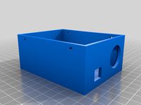
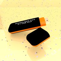
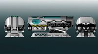
An enclosure for wireless DMX modules (often available on ebay). The enclosure has been designed to be screwed directly on to a female 3 pin XLR connector (M17x1.0 thread).
Also, a DC connector is added, so that the module can be powered by an external 5V power supply (for example an USB charger). Links to parts on eBay
Wireless DMX Module
Female Chassis mount DC Power connector
USB to DC adapter cable (straight)USB to DC adapter cable (angled)M3x12 screwsAssembly instructions
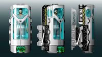
First insert the DC power connector in the base part, and tighten the nut on the DC connector on the inside.
Next, the antenna for the DMX module need to be mounted. Mount the antenna connector to the EndCap piece, and tighten the nut on the SMA connector. Now glue the EndCap to the body.
Now it is time to mount up the wires and do some soldering.
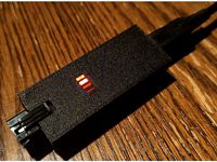
WARNING: Do NOT trust the colors on the wires on the plug/cable delivered with the module.
Check the attached picture for how the connections were on my modules (my markings with red text). I relocated the wires in the JST plug, so the coloring made more sense.
First, solder the power connections to the DC connector - remember to have an extra wire soldered to the negative pin of the DC connector - it should be used for the XLR connector.
Next, pass the D+, D- and GND wire through the hole in the end of the body, through the XlrPlug piece (remember to orient it correctly) and through the XlrRing piece. Solder the 3 wires to the 3 pins in on the XLR connector.
Pin 1 of the XLR is GND
Pin 2 of the XLR is D-
Pin 3 of the XLR is D+
Now assemble the XLR plug part. Insert the XlrRing into the XLR connector housing together with the XLR plug piece. Then tighten the XlrPlug piece to the back of the XLR connector.
Now carefully try to assemble everything. Connect the antenna to the PCB, and then JST plug to the PCB.The antenna cable can be located under the PCB and go back up - avoid to bend it too much, it will cause signal loss!
You might want to secure the PCB temporarily with a couple of screws while you glue the XLR connector piece together with the body. Once everything is in place, you can remove the temporary screws from the PCB, make sure the PCB is in place - put the lid on the top of the body, and tighten everything together with 4 M3x12mm screws.
will fit better.
Contributions are appreciated - it took me quite some time to get the design made in Fusion360, and a lot of test prints..
If you print a part, please remember to post a "make" picture
Update 2018-02-07: Improved body, lid and endcap added as version 2.1. XLR-Ring and and XLR-Plug parts are still the same.
Also, a DC connector is added, so that the module can be powered by an external 5V power supply (for example an USB charger). Links to parts on eBay
Wireless DMX Module
Female Chassis mount DC Power connector
USB to DC adapter cable (straight)USB to DC adapter cable (angled)M3x12 screwsAssembly instructions
First insert the DC power connector in the base part, and tighten the nut on the DC connector on the inside.
Next, the antenna for the DMX module need to be mounted. Mount the antenna connector to the EndCap piece, and tighten the nut on the SMA connector. Now glue the EndCap to the body.
Now it is time to mount up the wires and do some soldering.
WARNING: Do NOT trust the colors on the wires on the plug/cable delivered with the module.
Check the attached picture for how the connections were on my modules (my markings with red text). I relocated the wires in the JST plug, so the coloring made more sense.
First, solder the power connections to the DC connector - remember to have an extra wire soldered to the negative pin of the DC connector - it should be used for the XLR connector.
Next, pass the D+, D- and GND wire through the hole in the end of the body, through the XlrPlug piece (remember to orient it correctly) and through the XlrRing piece. Solder the 3 wires to the 3 pins in on the XLR connector.
Pin 1 of the XLR is GND
Pin 2 of the XLR is D-
Pin 3 of the XLR is D+
Now assemble the XLR plug part. Insert the XlrRing into the XLR connector housing together with the XLR plug piece. Then tighten the XlrPlug piece to the back of the XLR connector.
Now carefully try to assemble everything. Connect the antenna to the PCB, and then JST plug to the PCB.The antenna cable can be located under the PCB and go back up - avoid to bend it too much, it will cause signal loss!
You might want to secure the PCB temporarily with a couple of screws while you glue the XLR connector piece together with the body. Once everything is in place, you can remove the temporary screws from the PCB, make sure the PCB is in place - put the lid on the top of the body, and tighten everything together with 4 M3x12mm screws.
will fit better.
Contributions are appreciated - it took me quite some time to get the design made in Fusion360, and a lot of test prints..
If you print a part, please remember to post a "make" picture
Update 2018-02-07: Improved body, lid and endcap added as version 2.1. XLR-Ring and and XLR-Plug parts are still the same.
Similar models
grabcad
free

Female XLR Plug Internal
...female xlr plug internal
grabcad
pcb solderable female xlr plug. one can be obtained by deconstructing an xlr/dmx cable.
thingiverse
free

USB emulator enclosure
...in jst connectors. after passing wires through the input hole, i knotted the cable to prevent stress to the connectors and board.
3dwarehouse
free

5 Pin XLR
...5 pin xlr
3dwarehouse
5-pin xlr lighting connector used for dmx-512 protocol. #5pin_xlr #dmx #lighting #neutrik #switchcraft
thingiverse
free

XT60 2-6S to USB converter by Unboxingexperience7
...ctronics and a plug. simply put the module with the soldered xt60 female connector into the body and then cover it with the plug.
thingiverse
free

XLR / DMX Cap by Codycode
...ll latch on like a cable. to remove you will need to press the cable release and pull the cap off. exactly like removing a cable.
grabcad
free

D-Sub Connector ,7 Power Position 5+2 Combo Plug Male Pins Machined Pin 7W2 Gold Flash Panel Mount Wire Solder
...ire solder
grabcad
d-sub connector 7 power position 5+2 combo plug male pins machined pin 7w2 gold flash panel mount wire solder
grabcad
free

2 pin JST connector
...2 pin jst connector
grabcad
zh jst 2 pin male pcb connector
grabcad
free

5 pin JST connector
...5 pin jst connector
grabcad
zh jst 5 pin male pcb connector
thingiverse
free
Arduino Nano Addressable LED Case by MVstudios
...able leds can be powered directly and the jst sm connector can back feed power to the arduino eliminating the need for usb power.
grabcad
free

2 pins jst
...2 pins jst
grabcad
2-pin jst connector for use on pcbs
Bipsen
thingiverse
free

AM8 Y-Axis motor Rear Mount by bipsen
...o i added a bit more space, making room for a flanged m5x10 screw like the one available via http://www.ebay.com/itm/272699998259
thingiverse
free
Filament Storage (IKEA SAMLA) - 65L Drilling jig by bipsen
...spools in the 65l box.
the 32 mm pipe will need to be cut to a length of 447mm in order to match the mounting sockets in the box.
thingiverse
free

Pitan body for metal bowden fitting by bipsen
...ody and lid. these have not been test printed, so i am not 100% sure if the thread goes in the right direction. feedback desired.
thingiverse
free

AM8 Electronics Case - with fan on enclosure lid by bipsen
...an lid (mounted on the outside).
note: i have not printed the dual-fan lid, but it should be possible to mount 2 80mm fans on it.
thingiverse
free

Anet A8/AM8 E3D Direct drive baseplate for Pitan Extruder by bipsen
...er - to see how everything matches up - so please be patient with printing the parts until i have confirmed that things match up.
thingiverse
free

AM8 MKS bracket - dual mosfet and Z-splitter by bipsen
...ket is mounted to the am8 frame - this will reduce stress in the joints, so the bracket "tabs" won't break so easy.
thingiverse
free

HallON sensor for E3D carriage - AM8 by bipsen
...ution to address this - probably with a custom release button, and some brackets to be mounted on the left-hand side z extrusion.
thingiverse
free

The Stig x4 Mini figure (Fusion 360 design) by bipsen
...youtube.com/watch?v=cwxiaulrkfq&list=plpu7x-j_xjgnoscuk8wbzzmlza66rj1bw
and yes - "the stig" wears white gloves ;-)
thingiverse
free

Printed double IGUS Bearing block for E3D baseplate by bipsen
...he diameter, if it is too loose or tight when printed on your own printer - or send me a message, if you need a custom sized stl.
thingiverse
free

Anet A8 Frame Back Brace w/Y-Axis Belt Tension Rods - 25mm added by bipsen
...ginal back panel is probably needed. the bracket has not been test-printed yet - it will happen once i get the larger heated bed.
Xlr
3d_export
$39

Cadillac XLR
...cadillac xlr
3dexport
cadillac xlr,year 2004. model with high quality finishing on the outside and inside.
turbosquid
$9

XLR Connector
...del xlr connector for download as max, obj, 3ds, dae, and fbx on turbosquid: 3d models for games, architecture, videos. (1654345)
turbosquid
free

Salbot XLR
... available on turbo squid, the world's leading provider of digital 3d models for visualization, films, television, and games.
3d_ocean
$89

Cadillac XLR 2009
...y, in real units of measurement, qualitatively and maximally close to the original. model formats: - *.max (3ds max 2008 scanl...
3ddd
$1

cadillac XLR
...етализирован. объекты объединены в группы и имеют логические названия. hdri- карта не прилагается, так как не моя.
≃450 000 poly
3d_export
$10

Cadillac XLR tuning 3D Model
...del
3dexport
cadillac xlr general motors convertible tuning sport race american
cadillac xlr tuning 3d model laguf 17066 3dexport
3d_export
$99

Cadillac XLR 2009 3D Model
... 2006 2007 2008 2009 2-door coupe covertible sport us american general motors
cadillac xlr 2009 3d model humster3d 67646 3dexport
cg_studio
$99

Cadillac XLR 20093d model
...
.3ds .c4d .fbx .lwo .max .mb .obj - cadillac xlr 2009 3d model, royalty free license available, instant download after purchase.
turbosquid
$100

AMX Leclerc Xlr white
... amx leclerc xlr white for download as 3ds, max, obj, and fbx on turbosquid: 3d models for games, architecture, videos. (1456956)
3d_export
$5
XLR 3 Pins Male Connector 3D Model
...ale connector 3d model
3dexport
plug xlr connector realistic audio
xlr 3 pins male connector 3d model maguro.matto 87977 3dexport
Dmx
3ddd
$1
Стробоскоп Atomic 3000 DMX
... atomic
сценический cветовой прибор стробоскоп martin atomic 3000 dmx
3000ват
5600k color temperature
cg_studio
$80

Moving Heads wash light3d model
...truss system martin coemar wash cannon moving head intelligent dmx .3ds .c4d .dxf - moving heads wash light 3d...
3d_export
$10
LAD LED Par56 Spotlight 3D Model
...colour colorchanger changer light audio design scene stage rgb dmx studio high-quality 3d model of l.a.d. (light audio design)...
thingiverse
free

DMX Logo by rshakur
...dmx logo by rshakur
thingiverse
dmx logo
r.i.p man !!!!
thingiverse
free

DMX keychain by resi2307
...dmx keychain by resi2307
thingiverse
dmx famous raper from the ruff ryders
use the m600 to multiply color...
thingiverse
free

Knob Fader DMX Console
...knob fader dmx console
thingiverse
knob for normal audio or dmx faders
thingiverse
free

DMX Electronics Box by seajays
...dmx electronics box by seajays
thingiverse
a box to hold dmx controller for led lighting strips.
3dfindit
free

AL Cove DMX
...al cove dmx
3dfind.it
catalog: acclaim lighting
thingiverse
free
Wireless DMX Box
...r the wireless board led and switch had to be reamed out a little so it sat nicer and the switch wasn't accidentally pressed.
thingiverse
free

DIY DMX box by kefke44
...nder-10/)
the lid snap fits in place but there are some holes you can use to put zip-ties through to guarantee an even safer fit.
Wireless
3d_export
$5

Wireless headphones
...wireless headphones
3dexport
wireless headphones
3ddd
$1
Wireless Panasonic
...wireless panasonic
3ddd
panasonic , телефон
wireless panasonic
turbosquid
$20

Wireless speaker
...quid
royalty free 3d model wireless speaker for download as on turbosquid: 3d models for games, architecture, videos. (1544331)
turbosquid
$30

wireless Lamp
...ty free 3d model wireless lamp :) for download as max and obj on turbosquid: 3d models for games, architecture, videos. (1268614)
turbosquid
free

Wireless Headphone
... model wireless headphone for download as blend, obj, and fbx on turbosquid: 3d models for games, architecture, videos. (1696529)
3ddd
$1

JBL Micro Wireless
... micro , колонка , плеер
jbl micro wireless
3ddd
free

Apple Wireless Keyboard
...apple wireless keyboard
3ddd
apple , клавиатура
mental ray, apple wireless keyboard
turbosquid
$36
Wireless Mouse
...model wireless mouse for download as blend, fbx, dae, and obj on turbosquid: 3d models for games, architecture, videos. (1711548)
turbosquid
$35

wireless headphone
...del wireless headphone for download as max, fbx, obj, and 3ds on turbosquid: 3d models for games, architecture, videos. (1522997)
turbosquid
$25
Wireless router
... model wireless router for download as max, fbx, obj, and 3ds on turbosquid: 3d models for games, architecture, videos. (1516966)
Enclosure
3d_export
free
electrical enclosure
...l enclosure where electrical devices like (relays, contactors, busbars ) are kept in order to protect from hazardous environment.
turbosquid
$100

GPU Enclosure
...yalty free 3d model gpu enclosure for download as obj and stl on turbosquid: 3d models for games, architecture, videos. (1381061)
3d_export
$5
Electrical Enclosure
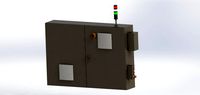
...ed. also has tower lights attaced on the top.<br>file format that are available:<br>.step<br>.obj<br>.stl
archive3d
free
Enclosure 3D Model
...closure 3d model
archive3d
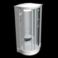
shower enclosure-acquarius- 3d model for interior 3d visualization.
archive3d
free
Enclosure 3D Model
...enclosure 3d model
archive3d
shower enclosure-omega- 3d model for interior 3d visualization.
archive3d
free
Enclosure 3D Model
...enclosure 3d model
archive3d
shower enclosure-vega - 3d model for interior 3d visualization.
archive3d
free
Enclosure 3D Model
...enclosure 3d model
archive3d
shower enclosure-zenith - 3d model for interior 3d visualization.
turbosquid
$20
shower enclosure
... available on turbo squid, the world's leading provider of digital 3d models for visualization, films, television, and games.
turbosquid
$14
Dumpster Enclosure
... available on turbo squid, the world's leading provider of digital 3d models for visualization, films, television, and games.
turbosquid
$25
3d printer enclosure
... model 3d printer enclosure for download as ipt, skp, and fbx on turbosquid: 3d models for games, architecture, videos. (1634310)
Module
turbosquid
$4

Module
...
turbosquid
royalty free 3d model module for download as max on turbosquid: 3d models for games, architecture, videos. (1259603)
3d_export
free

Martian module
...martian module
3dexport
martian module objects 18 textures are missing
design_connected
$39
Kennedee Moduls
...kennedee moduls
designconnected
kennedee moduls computer generated 3d model. designed by massaud, jean-marie.
design_connected
$39

Sayonara Moduls
...sayonara moduls
designconnected
bbb emmebonacina sayonara moduls computer generated 3d model. designed by decursu, giorgio.
design_connected
$27

Togo Moduls
...togo moduls
designconnected
ligne roset togo moduls computer generated 3d model. designed by ducaroy, michel.
design_connected
$34
Nuvola Moduls
...nuvola moduls
designconnected
bonaldo nuvola moduls 2-seater computer generated 3d model. designed by giuseppe viganò.
3d_export
free
Hibernation module
...hibernation module
3dexport
design_connected
$27

Sabi moduls
...sabi moduls
designconnected
paola lenti sabi moduls 2-seater computer generated 3d model. designed by francesco rota.
3d_export
$50

pls concrete module
...pls concrete module
3dexport
pls concrete module<br>pls with concrete mobile mixer module m5
turbosquid
free
Hibernation module
...squid
free 3d model hibernation module for download as blend on turbosquid: 3d models for games, architecture, videos. (1667696)