Cults

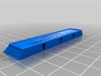
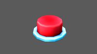
Wireless Button Presser
by Cults
Last crawled date: 6 years, 2 months ago
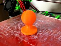
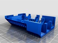
This is the most pointless thing (though it does have a point) that I have ever designed. And I blame Oleg, who really wanted one. It is the perfect way to waste half a gig of memory and the decent processing capability of a Raspberry Pi Zero W on the very simple task of pressing a button.
Now, since the Raspberry Pi Zero W is wireless, and since it is running Robo4J, you can press the button wirelessly over a rest API. Or log into the Raspberry pi and run the code to press a button. But no matter what you do, you've basically wasted your precious and overpowered Raspberry Pi Zero W on the silly task of pressing a button. Congratulations.
That said, it does provide a simple example of how you can control a servo using Robo4J, a Raspberry Pi Zero W and no additional hardware. So maybe there is a point to all of this, after all. Maybe.
What you need:
Sacrificial Raspberry Pi Zero W (1)
Screws (2.2 x 4.5mm) (7)
Nano Servo (e.g. Turnigy T541BBD) (1)
Links to videos of the stupid thing in action:
https://www.youtube.com/watch?v=_hPZF4_aZSA
https://www.youtube.com/watch?v=8uxH6LvMODM
Link to the source:
https://github.com/thegreystone/button-activator
How to build:
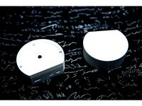
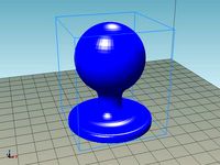
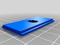
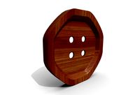
Print two of the point halves, and one of everything else. Take a bit of piano wire (0.5 mm thick) and bend it so that it goes a bit into the hole of one of the point halves, but does not come out the other end. Cut the other end and bend it into a Z so the servo arm can hold it. The point should stick out a tiny bit when put it in the point holder so that the piano wire touches the bottom. Glue the halves together
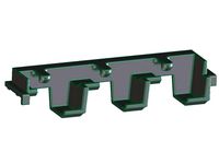
Stick the point assembly into the holder, and take the servo arm and put it on the piano wire on the point assembly from the guide hole on the side of the point holder. Put some servo tape on the servo, but do not remove the cover on the side facing away from the servo yet.
Connect the servo to the Raspberry Pi (red goes to 5V (pin 2), brow/black goes to GND (pin 6) and yellow/white goes to GPIO 18 (pin 12)). I would recommend building a Dupont 6p to 3p servo adapter cable, and then let red be in the first slot, black in the third slot and white in the sixth slot. That way you can just plug the cable in with red in the top outer corner of the Raspberry Pi header.
Put the servo down in its place, and run the Robo4J program, without the arm attached. Once the servo is done and has returned to its low point, put the servo arm as low as it can be, almost letting the piano wire touch the button, and see that the trim and servo end points are where they should by running the Robo4J program. If not, modify the example settings file to your liking.
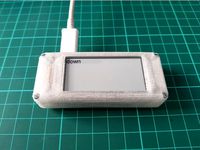
Remove the cover on the servo tape and tape the servo to its gradle. Use a small screwdriver to screw on the servo arm (you can go through one of the USB port openings). Screw the Raspberry Pi onto the bottom with four screws. After ensuring that everything works, screw on the lid. Done!
Now, since the Raspberry Pi Zero W is wireless, and since it is running Robo4J, you can press the button wirelessly over a rest API. Or log into the Raspberry pi and run the code to press a button. But no matter what you do, you've basically wasted your precious and overpowered Raspberry Pi Zero W on the silly task of pressing a button. Congratulations.
That said, it does provide a simple example of how you can control a servo using Robo4J, a Raspberry Pi Zero W and no additional hardware. So maybe there is a point to all of this, after all. Maybe.
What you need:
Sacrificial Raspberry Pi Zero W (1)
Screws (2.2 x 4.5mm) (7)
Nano Servo (e.g. Turnigy T541BBD) (1)
Links to videos of the stupid thing in action:
https://www.youtube.com/watch?v=_hPZF4_aZSA
https://www.youtube.com/watch?v=8uxH6LvMODM
Link to the source:
https://github.com/thegreystone/button-activator
How to build:
Print two of the point halves, and one of everything else. Take a bit of piano wire (0.5 mm thick) and bend it so that it goes a bit into the hole of one of the point halves, but does not come out the other end. Cut the other end and bend it into a Z so the servo arm can hold it. The point should stick out a tiny bit when put it in the point holder so that the piano wire touches the bottom. Glue the halves together
Stick the point assembly into the holder, and take the servo arm and put it on the piano wire on the point assembly from the guide hole on the side of the point holder. Put some servo tape on the servo, but do not remove the cover on the side facing away from the servo yet.
Connect the servo to the Raspberry Pi (red goes to 5V (pin 2), brow/black goes to GND (pin 6) and yellow/white goes to GPIO 18 (pin 12)). I would recommend building a Dupont 6p to 3p servo adapter cable, and then let red be in the first slot, black in the third slot and white in the sixth slot. That way you can just plug the cable in with red in the top outer corner of the Raspberry Pi header.
Put the servo down in its place, and run the Robo4J program, without the arm attached. Once the servo is done and has returned to its low point, put the servo arm as low as it can be, almost letting the piano wire touch the button, and see that the trim and servo end points are where they should by running the Robo4J program. If not, modify the example settings file to your liking.
Remove the cover on the servo tape and tape the servo to its gradle. Use a small screwdriver to screw on the servo arm (you can go through one of the USB port openings). Screw the Raspberry Pi onto the bottom with four screws. After ensuring that everything works, screw on the lid. Done!
Similar models
thingiverse
free
Wireless Button Presser by Graystone
...openings). screw the raspberry pi onto the bottom with four screws. after ensuring that everything works, screw on the lid. done!
thingiverse
free

Raspberry Pi Zero W + Zero Camera Casing by eix0r
...
edit: just to clarify this is for the pi zero cam not the standard pi cam there are plenty of housings for the pi cam out there.
thingiverse
free

DryBox Web Dashboard by cdow
... the dashboard using http://:5000 from any computer on your network.
the dieselpunk font was used for the graphic in the picture.
thingiverse
free

Raspberry Pi Zero Simple Open Case by noisycarlos
...pen (so you can remove it from the case while plugged in).
it prints in 10-20 minutes, and the pi zero board should just snap in.
thingiverse
free
Raspberry Pi Zero W Casing (Headless) by Tarjei85
...spberry pi zero w.
was designed to house a raspberry pi zero w running headless as a network-wide instance of pihole (ad-blocker)
thingiverse
free

cover case for Raspberry Pi Zero W by Sh1n0
...i used this file.
i also uploaded ipt files so that you can edit with fusion 360.
screws are m2.5 x 8mm (jis).
enjoy 3d printing!
thingiverse
free

Raspberry Pi Bumper Button Holder by techyg
...ton that i am using with this design:https://www.amazon.com/gp/product/b01dz8cowk/ref=oh_aui_detailpage_o01_s01?ie=utf8&psc=1
thingiverse
free
StickPi case by assadollahi
...n the back, etc, see my blog entry:https://assadollahi.de/stickpi-a-raspberry-pi-zero-w-with-gpio-buttons-and-an-e-paper-display/
thingiverse
free

raspberry pi zero W case by ntchris
...duce some heat while running. but pla should work just fine i believe.
also require 4pcs 2.5mm or 2.6mm , 8mm long tapping screw.
thingiverse
free

Raspberry Pi Zero WiFi Camera Case for use with GPIO by Timo94
...4
thingiverse
quick remix so you can use the gpio pins while your raspberry pi zero is in the case.
please download on youmagine
Presser
turbosquid
$10
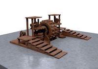
Medieval Wine Presser Conspt 3D Model
...oad as blend, max, max, ige, fbx, dae, obj, max, stl, and 3ds on turbosquid: 3d models for games, architecture, videos. (1585250)
3d_export
$250

3d drawings bom list for fully automated pocket packing machines
...feeder, bag-packing, bag-packing, bag-picking, bag-picking, bag-drawing, outer frame assembly, presser guide, shock bag, etc.contains list bom and 3d models<br>the...
thingiverse
free
Coffee presser by ArGabriel
...coffee presser by argabriel
thingiverse
coffee presser for italian coffee maker.
diametr 54 mm.
thingiverse
free

Drone motor presser by creativesam
...drone motor presser by creativesam
thingiverse
drone motor presser for 8mm brush motors
thingiverse
free

Coffee presser by opuigcerver
...ith the spoon. this coffee presser helps you to do a tasty coffee.
dimension of base: 68mm x 5mm
dimension of handle: 10mm x 30mm
thingiverse
free
Play-Doh Presser Design by MNutt_STS
...n by mnutt_sts
thingiverse
a plate to insert in the play-doh presser which will change the shape that the play-doh comes out in.
thingiverse
free
Coffee presser for Italian coffee maker. by ArGabriel
...fee presser for italian coffee maker. by argabriel
thingiverse
coffee presser for italian coffee maker. (small)
diametr 41,5 mm.
thingiverse
free
no touch door opener with keypad presser by odxbot12
...opener with keypad presser by odxbot12
thingiverse
this is a no touch door opener for corona virus with built in key pad presser
thingiverse
free
Path of Exile Professional Presser by rafaelguima
...path of exile professional presser by rafaelguima
thingiverse
be a flask professional with this tool.
thingiverse
free
PRESSER Foot BERNINA E1 TRAY by dudu665
...e hard to get i copied an original one.
tray for presser foot type e1 (with big old sensor) - belonging to their accessories box.
Wireless
3d_export
$5

Wireless headphones
...wireless headphones
3dexport
wireless headphones
3ddd
$1
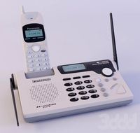
Wireless Panasonic
...wireless panasonic
3ddd
panasonic , телефон
wireless panasonic
turbosquid
$20

Wireless speaker
...quid
royalty free 3d model wireless speaker for download as on turbosquid: 3d models for games, architecture, videos. (1544331)
turbosquid
$30

wireless Lamp
...ty free 3d model wireless lamp :) for download as max and obj on turbosquid: 3d models for games, architecture, videos. (1268614)
turbosquid
free

Wireless Headphone
... model wireless headphone for download as blend, obj, and fbx on turbosquid: 3d models for games, architecture, videos. (1696529)
3ddd
$1
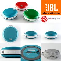
JBL Micro Wireless
... micro , колонка , плеер
jbl micro wireless
3ddd
free

Apple Wireless Keyboard
...apple wireless keyboard
3ddd
apple , клавиатура
mental ray, apple wireless keyboard
turbosquid
$36
Wireless Mouse
...model wireless mouse for download as blend, fbx, dae, and obj on turbosquid: 3d models for games, architecture, videos. (1711548)
turbosquid
$35

wireless headphone
...del wireless headphone for download as max, fbx, obj, and 3ds on turbosquid: 3d models for games, architecture, videos. (1522997)
turbosquid
$25
Wireless router
... model wireless router for download as max, fbx, obj, and 3ds on turbosquid: 3d models for games, architecture, videos. (1516966)
Zero
3ddd
$1

ZERO, BEAM
...zero, beam
3ddd
zero
поворотная люстра zero , beam
design_connected
$9
Zero-in
...zero-in
designconnected
established & sons zero-in tables computer generated 3d model. designed by jay osgerby .
3ddd
free
Sub-Zero
...sub-zero
3ddd
sub-zero , голова
sub-zero corona render!
3ddd
$1
Metalspot / Zero
...metalspot / zero
3ddd
metalspot
metalspot zero
3ddd
$1
Catalano Zero
...catalano zero
3ddd
catalano , унитаз
catalano zero
3ddd
$1

SUB ZERO
... sub zero
the first and only 3d model of sub zero refrigerator.
the model is very accurate.
turbosquid
free

Zero
... available on turbo squid, the world's leading provider of digital 3d models for visualization, films, television, and games.
turbosquid
free
Zero
... available on turbo squid, the world's leading provider of digital 3d models for visualization, films, television, and games.
turbosquid
free
Zero
... available on turbo squid, the world's leading provider of digital 3d models for visualization, films, television, and games.
3ddd
$1

ZERO / Hide
...zero / hide
3ddd
zero
polys: 25486
wire-spline
Raspberry
3d_export
free
raspberry
...raspberry
3dexport
3d model of a raspberry. i tried to make it realistic.
turbosquid
$27
Raspberries
...y free 3d model raspberries for download as max, obj, and stl on turbosquid: 3d models for games, architecture, videos. (1354176)
turbosquid
$14
Raspberries
...y free 3d model raspberries for download as max, obj, and fbx on turbosquid: 3d models for games, architecture, videos. (1364663)
3d_export
$5
raspberry pi
...raspberry pi
3dexport
carcasa para la raspberry pi
turbosquid
$99
Raspberry
... available on turbo squid, the world's leading provider of digital 3d models for visualization, films, television, and games.
turbosquid
$10

raspberries
... available on turbo squid, the world's leading provider of digital 3d models for visualization, films, television, and games.
archive3d
free

Raspberries 3D Model
...raspberries 3d model archive3d raspberries raspberry raspberries n300911 - 3d model (*.3ds) for interior 3d...
3d_export
$5

raspberry fruit
...raspberry fruit
3dexport
3d_export
$5

raspberry
...y different sizes. their color ranges from light burgundy to pink. there are formats: obj, 3ds, blend, dae, fbx, mtl.<br>:)
evermotion
$12

raspberries 23 am130
...evermotion raspberries 23 am130 evermotion key 23 food fruit raspberry fruits am130 raspberries highly detailed 3d model of raspberries...
Pi
design_connected
$11
Pi
...pi
designconnected
ligne roset pi chairs computer generated 3d model. designed by thibault desombre.
3d_export
$5
raspberry pi
...raspberry pi
3dexport
carcasa para la raspberry pi
turbosquid
$18
pied
... available on turbo squid, the world's leading provider of digital 3d models for visualization, films, television, and games.
3ddd
$1
Emme pi light
...emme pi light
3ddd
emme pi light
люста emme pi light
3ddd
$1
Emme pi light
...emme pi light
3ddd
emme pi light
бра классическое emme pi light
3ddd
$1

Emme Pi Light
...emme pi light
3ddd
emme pi light
3ddd
$1

Emme Pi Light
...emme pi light
3ddd
emme pi light
design_connected
$16
Pi-Air
...pi-air
designconnected
living divani pi-air lounge chairs computer generated 3d model. designed by harry & camila.
3d_ocean
$15
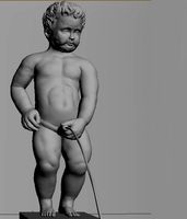
Manneken Pis
...picting a naked little boy urinating into a fountain’s basin. (wikipedia) the model was sculpted in blender 2.70a rendered wit...
3ddd
$1
Emme pi light
...emme pi light
3ddd
emme pi light
люстра классическая фирма: emme pi light
артикул: 3595/5/cot/12/wh
Button
archibase_planet
free
Buttons
...buttons
archibase planet
lift elevator call buttons
elevator call buttons - 3d model for interior 3d visualization.
3ddd
$1
Button
... button , john reeves
набор мебели button от дизайнера john reeves
3d_export
$5
Button
...button
3dexport
smd button<br>verts 2.180<br>faces 3.848
turbosquid
$4

Button
...
turbosquid
royalty free 3d model button for download as fbx on turbosquid: 3d models for games, architecture, videos. (1297941)
turbosquid
$1

Button
...
turbosquid
royalty free 3d model button for download as fbx on turbosquid: 3d models for games, architecture, videos. (1392935)
turbosquid
$9
buttons
...id
royalty free 3d model buttons for download as max and fbx on turbosquid: 3d models for games, architecture, videos. (1404875)
turbosquid
$6

button
...uid
royalty free 3d model button for download as 3dm and max on turbosquid: 3d models for games, architecture, videos. (1669204)
turbosquid
$5
Button
...uid
royalty free 3d model button for download as max and fbx on turbosquid: 3d models for games, architecture, videos. (1710868)
turbosquid
$3

Button
...quid
royalty free 3d model button for download as ma and obj on turbosquid: 3d models for games, architecture, videos. (1510524)
turbosquid
$3
Button
...quid
royalty free 3d model button for download as ma and obj on turbosquid: 3d models for games, architecture, videos. (1509961)
W
3ddd
$1
chair W
...chair w
3ddd
chair w
3ddd
$1

кресло w
...кресло w
3ddd
капитоне
кресло w
3ddd
$1
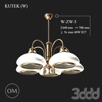
KUTEK (W) W-ZW-5
...kutek (w) w-zw-5
3ddd
kutek
3d модель люстри (w) w-zw-5 фабрики kutek. в архиве: max2012, obj, fbx, mat.(два варианта металла)
3ddd
$1
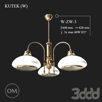
KUTEK (W) W-ZW-3
...kutek (w) w-zw-3
3ddd
kutek
3d модель люстри (w) w-zw-3 фабрики kutek. в архиве: max2012, obj, fbx, mat. (два варианта металла)
3ddd
$1
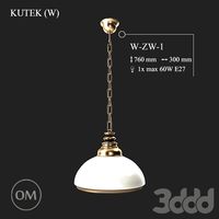
KUTEK (W) W-ZW-1
...kutek (w) w-zw-1
3ddd
kutek
3d модель люстри (w) w-zw-1 фабрики kutek. в архиве: max2012, obj, fbx, mat (два варианта металла).
3ddd
free
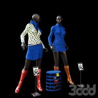
aneken W&W
...aneken w&w
3ddd
2 женских манекена, ценники и фолио. материалы и текстуры прилагаются.
design_connected
$9
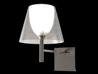
KTribe W
...ktribe w
designconnected
ktribe w computer generated 3d model. designed by starck, philippe.
design_connected
$16

Troy W
...troy w
designconnected
magis troy w computer generated 3d model. designed by wanders, marcel.
turbosquid
$9

Menu - Benjamin Hubert - W W Carafe
... available on turbo squid, the world's leading provider of digital 3d models for visualization, films, television, and games.
turbosquid
$9

Menu - Benjamin Hubert - W W Carafe
... available on turbo squid, the world's leading provider of digital 3d models for visualization, films, television, and games.