3dExport
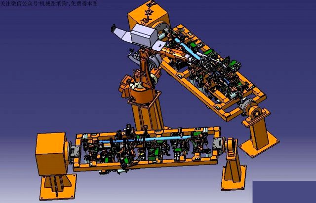
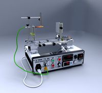
welding jig for welding of instrument frame welding beam
by 3dExport
Last crawled date: 1 year, 10 months ago
the instrument beam assembly is made of 18 kinds of small stamping parts, which is required to meet the production program of 60000 vehicles per year. the number of stamping parts of the instrument beam is large, and the thickness of the plate is many, so it is difficult to weld the assembly. according to the process analysis, the welding method is suitable for co2 gas shielded gas welding, with the length of 1420mm and the number of weld joints being 45 sections. because the welding position is in three-dimensional cross distribution and the position of each support has the requirements of assembly accuracy, the automation requirements for this station are high. manual welding can not meet the requirements in terms of welding quality, production rhythm and product stability. therefore, the final process plan determines that the assembly will be welded with co2 gas shielded welding for all welding points through welding robot workstation,
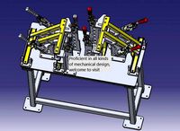
determine the height of the robot and the distance from the front and rear left and right, ensure that all welding points are covered in the working range that the robot welding can reach. the most reliable method for optimizing design is to simulate the actual welding work through robot simulation software. the method is to add 3d model of station fixture, work piece and welding, and assemble and debug the workstation in virtual environment, and find out whether it is dry or not in this way, the relative size of each part can be adjusted to the best.
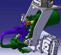
each station can be reversed around the horizontal axis of the positioner, and its posture can coordinate with the robot during welding to meet the requirements of welding process. it is mainly composed of two external axis servo motors (i.e. displacement machine) and their reducer, coordination software, converter, cable, two sets of fixture turning mechanism, servo drive system, etc. two sets of turning mechanism are driven by positioner, and the system is realized by robot control system.
the driven shaft is connected with the connecting plate and is installed on the mounting base. the turning mechanism of welding fixture is connected with the connecting plate, and the machining error and installation of welding fixture are considered. the height of positioner and driven shaft can be adjusted. the driven shaft is universal rotary bearing, so as to avoid machining error and make installation and maintenance convenient.
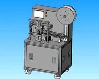
cleaning and silicone oil spraying device: a total of 1 set, consisting of cleaning mechanism, clamping mechanism and silicon oil spraying mechanism. the actions are as follows:
robot moves welding to cleaning device - cleaning device clamping welding - automatic cleaning - robot moves welding to silicon oil spraying place - spraying silicon oil - robot moves welding back to its original position.
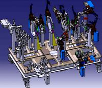
the welding clamp is of frame structure, which is convenient for robot welding to approach the workpiece. there are 25 movable locating pins, 2 fixed locating pin sleeves and 3 fixing pins, so that the workpiece can be taken out of the fixture. the second station is the same as the first station to increase the capacity to avoid the waiting time of the robot, so that the robot does not stop working when the manual parts are put on and taken, and the working efficiency is improved.
determine the height of the robot and the distance from the front and rear left and right, ensure that all welding points are covered in the working range that the robot welding can reach. the most reliable method for optimizing design is to simulate the actual welding work through robot simulation software. the method is to add 3d model of station fixture, work piece and welding, and assemble and debug the workstation in virtual environment, and find out whether it is dry or not in this way, the relative size of each part can be adjusted to the best.
each station can be reversed around the horizontal axis of the positioner, and its posture can coordinate with the robot during welding to meet the requirements of welding process. it is mainly composed of two external axis servo motors (i.e. displacement machine) and their reducer, coordination software, converter, cable, two sets of fixture turning mechanism, servo drive system, etc. two sets of turning mechanism are driven by positioner, and the system is realized by robot control system.
the driven shaft is connected with the connecting plate and is installed on the mounting base. the turning mechanism of welding fixture is connected with the connecting plate, and the machining error and installation of welding fixture are considered. the height of positioner and driven shaft can be adjusted. the driven shaft is universal rotary bearing, so as to avoid machining error and make installation and maintenance convenient.
cleaning and silicone oil spraying device: a total of 1 set, consisting of cleaning mechanism, clamping mechanism and silicon oil spraying mechanism. the actions are as follows:
robot moves welding to cleaning device - cleaning device clamping welding - automatic cleaning - robot moves welding to silicon oil spraying place - spraying silicon oil - robot moves welding back to its original position.
the welding clamp is of frame structure, which is convenient for robot welding to approach the workpiece. there are 25 movable locating pins, 2 fixed locating pin sleeves and 3 fixing pins, so that the workpiece can be taken out of the fixture. the second station is the same as the first station to increase the capacity to avoid the waiting time of the robot, so that the robot does not stop working when the manual parts are put on and taken, and the working efficiency is improved.
Similar models
3d_export
$10
arc welding workstation with dual robots and double clamps
...lding robot in turn. the fixture is shifted by the positioner to realize the welding of different positions of the robot welding.
grabcad
free

Welding fixture 3
...welding fixture 3
grabcad
robotic welding fixture and positioner
grabcad
free

L positioner for welding application
...he workpiece in order to make welding surface accessible as per the welder need and can be automated using the robot for welding.
3d_export
$15
welding fixture for connecting plate of automobile front longitudinal beam
...front longitudinal beam connecting plate and its reinforcing plate, the lower swing arm mounting plate and its reinforcing parts.
grabcad
free

Fixture for shaft welding
...fixture for shaft welding
grabcad
fixture for welding shaft assembly.
3d_export
$14

design of arc welding workstation with single robot and double fixture
...trictions on the overall size of the workpiece to be welded. generally, the diameter of the welded workpiece is less than 0.6 mm.
grabcad
free

ABB Workpiece positioners
...abb positioners are optimized to be used for manipulating of
workpieces in arc welding, thermal cutting and other applications.
grabcad
free

Welding fixture for positioner
...welding fixture for positioner
grabcad
welding fixture for spot welding
3d_export
$27
robot automatic welding workstation for automobile hood
...e, which is a rare reference for automobile welding equipment. catia r20 assembly structure source document, welcome to download!
grabcad
free

Robotic Welding station for Spoolwelding
...obotic welding station for spoolwelding
grabcad
conceptual design of robotic welding station, with fixtures and structural base.
Jig
turbosquid
$25
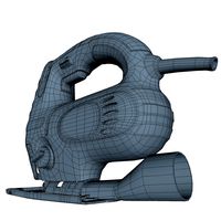
jig-saw_mid_SM
...uid
royalty free 3d model jig-saw_mid_sm for download as obj on turbosquid: 3d models for games, architecture, videos. (1244761)
turbosquid
$20
jig-saw_low
...osquid
royalty free 3d model jig-saw_low for download as obj on turbosquid: 3d models for games, architecture, videos. (1244760)
turbosquid
$10

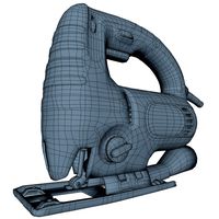
jig-saw_hi
...bosquid
royalty free 3d model jig-saw_hi for download as obj on turbosquid: 3d models for games, architecture, videos. (1244757)
turbosquid
$7

Jig Armchair
...squid
royalty free 3d model jig armchair for download as max on turbosquid: 3d models for games, architecture, videos. (1648936)
turbosquid
$5

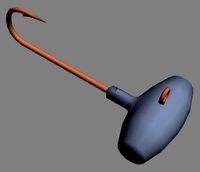
Jig Tail
... available on turbo squid, the world's leading provider of digital 3d models for visualization, films, television, and games.
turbosquid
$5
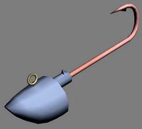
Jig Head
... available on turbo squid, the world's leading provider of digital 3d models for visualization, films, television, and games.
turbosquid
$5

Jig Head
... available on turbo squid, the world's leading provider of digital 3d models for visualization, films, television, and games.
turbosquid
$5

Jig Head
... available on turbo squid, the world's leading provider of digital 3d models for visualization, films, television, and games.
turbosquid
$5
Jig Head
... available on turbo squid, the world's leading provider of digital 3d models for visualization, films, television, and games.
turbosquid
$5

Jig Head
... available on turbo squid, the world's leading provider of digital 3d models for visualization, films, television, and games.
Welding
3d_export
$8
welding of electric welding machine
...ng. the melted welding wire penetrates into the parts to be welded. after cooling, the objects to be welded are firmly connected.
3d_export
$5

welded anchor
...welded anchor
3dexport
welded anchor
3d_export
$12
mbt welding fixture
... be used for welding design reference, welcome to download and learn from friends in need. the model contains stp general format.
turbosquid
$35

Welding Robot
...id
royalty free 3d model welding robot for download as blend on turbosquid: 3d models for games, architecture, videos. (1645667)
turbosquid
$2

Welding Robot
...id
royalty free 3d model welding robot for download as blend on turbosquid: 3d models for games, architecture, videos. (1480421)
turbosquid
$10

Welding Machine
...ree 3d model welding machine for download as ma, obj, and fbx on turbosquid: 3d models for games, architecture, videos. (1176188)
3d_export
$10

Welding apparatus 3D Model
...welding apparatus 3d model
3dexport
welding apparatus burner gas-jet
welding apparatus 3d model gaj15 60372 3dexport
3d_export
$20
ultrasonic welding machine welding of nose bar outside mask
...and discharging. the drawing file is sw2016 version with step neutral format. it has a good reference value. welcome to download.
3d_export
$21
welding fixture for automobile body
...ile welding line. we must design welding line suitable for automobile and strive to improve the design and manufacturing ability.
Instrument
3d_export
$5
measuring instrument
...measuring instrument
3dexport
measuring instrument
turbosquid
$99
Instrument
... available on turbo squid, the world's leading provider of digital 3d models for visualization, films, television, and games.
3d_export
$45
African instruments
...african instruments
3dexport
a lot african instruments music as the marimba kora and conga
archibase_planet
free

Instrument box
...base planet
instrument box toolware tool kit
instrument box n050114 - 3d model (*.gsm+*.3ds+*.max) for interior 3d visualization.
turbosquid
$269
Chimes musical instruments palace instruments chinese musical instruments
...s
turbosquid
royalty free 3d model chimes for download as ma on turbosquid: 3d models for games, architecture, videos. (1434928)
3d_export
$5

Surgical Instrument
...surgical instrument
3dexport
surgical instruments that can be used in movies and games, suitable for hospitals.
archive3d
free

Instrument 3D Model
...
fiddle musical instrument
instrument 1 - 3d model (*.gsm+*.3ds) for interior 3d visualization.
turbosquid
$25

Dental instruments
...
royalty free 3d model dental instruments for download as max on turbosquid: 3d models for games, architecture, videos. (1594603)
turbosquid
$5
musical instrument
...oyalty free 3d model musical instrument for download as blend on turbosquid: 3d models for games, architecture, videos. (1690160)
3d_export
$10

Battery Fpc Instrument
...battery fpc instrument
3dexport
fpc battery instrument musical
Beam
archibase_planet
free
Beam
...beam
archibase planet
beam camber-beam hammer-beam
balance beam 2 - 3d model for interior 3d visualization.
design_connected
$16

Beam
...beam
designconnected
van rossum beam computer generated 3d model. designed by rossum, van.
design_connected
$11
Beam
...beam
designconnected
mdf italia beam computer generated 3d model. designed by arrivillaga, luis alberto.
turbosquid
$25

beam
...am
turbosquid
royalty free 3d model beam for download as stl on turbosquid: 3d models for games, architecture, videos. (1674400)
turbosquid
free

beam
... available on turbo squid, the world's leading provider of digital 3d models for visualization, films, television, and games.
3ddd
$1

ZERO, BEAM
...zero, beam
3ddd
zero
поворотная люстра zero , beam
archive3d
free

Beam 3D Model
...archive3d
beam camber-beam hammer-beam
balance beam 2 - 3d model for interior 3d visualization.
3ddd
free
Studio Beam
... navy
светильники studio beam
модели: mariner, ocean mariner, navy.
могут быть в разных цветах
3ddd
$1
Studio Beam
...grupius
производитель studio beam
модели: edison’s rocket pendant, edison’s rocket table lamp,romanov,elena pendant,grupius 1919.
design_connected
$11
I-Beam
...i-beam
designconnected
glas italia i-beam computer generated 3d model. designed by massaud, jean-marie.
Frame
archibase_planet
free
Frame
...frame
archibase planet
frame photo frame
frame n190813 - 3d model (*.gsm+*.3ds) for interior 3d visualization.
archibase_planet
free
Frame
...frame
archibase planet
frame photo frame
frame n071113 - 3d model (*.gsm+*.3ds) for interior 3d visualization.
3ddd
$1

Frame
...frame
3ddd
frame
3ddd
free
Frame
...frame
3ddd
frame
archibase_planet
free

Frame
...frame
archibase planet
frame mirror frame ornament
frame n260113 - 3d model (*.gsm+*.3ds) for interior 3d visualization.
archibase_planet
free

Frame
...frame
archibase planet
frame photo frame
frame photo n190813 - 3d model (*.gsm+*.3ds) for interior 3d visualization.
archibase_planet
free
Frame
...frame
archibase planet
frame window window frame
frame 1 - 3d model (*.gsm+*.3ds) for interior 3d visualization.
archibase_planet
free
Frame
...frame
archibase planet
frame window frame window
frame 3 - 3d model (*.gsm+*.3ds) for interior 3d visualization.
archibase_planet
free
Frame
...frame
archibase planet
frame wall frame decoration
frame 1 - 3d model (*.gsm+*.3ds) for interior 3d visualization.
archibase_planet
free
Frame
...frame
archibase planet
frame window window frame
frame 2 - 3d model (*.gsm+*.3ds) for interior 3d visualization.