Thingiverse
Voron 1.8 250Z mod by jltx
by Thingiverse
Last crawled date: 4 years, 6 months ago
Here is a very simple quick mod for Voron 1.8 to increase your Z height from 230 to 250 mm using the stock linear shafts and lead screws from official BOM. How? because there is extra range availble from the stock assembly. They use the same extrusion for both the Y linear rail and to anchor the Z rods. So this means the rods are longer than needed (as defined) and the lead screws are just a common size, i.e. easy to find and cheaper, thus already support longer Z travel.
This mod took me less than 30 minutes to install and works great. You can do it before or after assembly depending where you are on build. Note that the side panels and doors will need to be 20 mm longer (if you haven't ordered yet) or some other modification needed to cover that added space at the bottom. You will also need four M5x35 screws for the extended feet. I got some at HD for a couple bucks.
The basic idea is you lower the bottom frame Z rails 20 mm to allow the bed to drop further. You replace the top Z retainers with extenders and add foot risers to the bottom to keep the same clearance for motors and power supply. Update your firmware config to indicate 250mm for Z. Done.
Note that the first photo shows the bed beyond home, maybe -10mm, because bed is not installed. There is still some gap when fully assembled.
Printing parts:
Only the Z retainers should be ABS as they will be inside the enclosure. The feet risers can be whatever filament. I would recommend PLA or PETG for the supplied jigs for dimensional accuracy.
Process:
You need to drill new access holes (or for the first time if you are still building). Remove the four rubber feet if installed. I provided a simple drilling jig that you screw into the tapped end where the foot goes, to position and help align the drill (add some grease to drill bit tip before each hole). Don't forget to rotate the jig 90 degrees to drill the access holes for the front and rear extrusions since you want to lower those too. It took me <5 minutes to drill the holes, and that was with the printer already assembled. So don't be scared off because that is the hardest step.
Assembly
Assemble frame as normal, just using the lower access holes, making sure all is square
Note you can use the framing jig to set the exact spacing for the middle Y axis extrusion as well as help with anti-rotation by fitting in extrusion slots where they meet. See photo examples
Clip on foot extension to each corner with the narrow side toward printer center. The narrow allows clearance for side skirts
Screw on rubber foot with M5x35. I added a #10 washer too, but optional
Installing Z axis. You can either follow the assembly guide, just replacing the top Z retainers with this mod version, OR follow what I feel is a simpler assembly outlined next (I've done it both ways).
Optional
NOTE: this differs from the official assembly guide so you won't have to awkwardly try to slide the Z axis in and tip the printer over.
Do NOT attach the Z bearing blocks to the bed frame (as shown pg 44), or remove them if you did already
Instead slide one bearing block onto each of the four rods
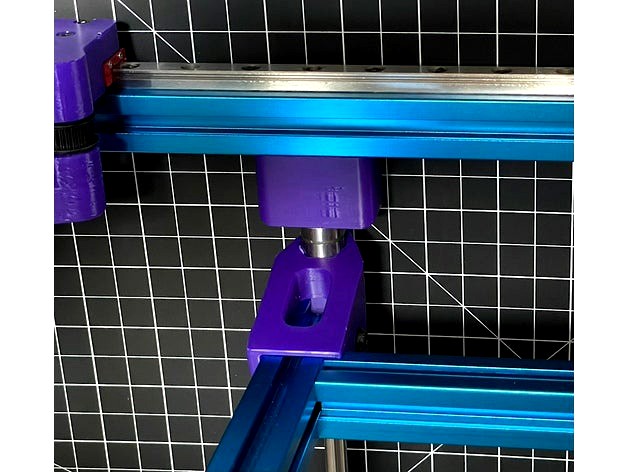
Attach the Z retainer brackets onto rod ends with the taller ones from this mod at the top, similar to pg 47 of guide but without the bed extrusions attached yet
Note the orientation of the bearing blocks with the angled side toward top and the screw holes to the outside. You can test fit on the bed frame without screwing to double check
You now have four loose rods with bearings and retainers attached and we are going to install each rod one at a time
Take a front rod and place it between the bottom and middle extrusion. A nice side benefit of this mod is the top retainer has a bit extra depth to allow for imperfect rod lengths
Screw the bottom down loosely with two M5x10 and the top loosely with two M5x16
Use the frame jigs to precisely space the front rod to inside front extrusion (this replaces the 44 mm spacing step on pg 50 and achieves exact results). See photo
Tighten down the screws and double check the spacing using same jig at both ends of rod
Because your frame is square, the front rod is now parallel to frame and thus plumb
Repeat same steps for other front rod
Loosely attach each rear rod between the extrusions, spaced behind front rods by bed frame width, which you can use to eyeball. Do not tighten! We will fix later
Now rotate each bearing block away from center of printer and slide bed frame and rest on ground. Note orientation of front bed mount with flat side on top
Rotate bearing blocks back over bed frame and attach loosely. Do not tighten! You can slide rear rods fore/aft as needed to line up to bed frame
Now you de-rack the Z axis. I found this is easiest with the printer on its side (not front or back or upright). This way you can easily slide the bed side to side instead of up and down and feel any binding. You iterate a few times to get it smooth. The front rods are pretty close to perfect so focus on fixing rear rods, then bearing blocks then probably repeat pass on rear rods. Don't over tighten bearing blocks as you can introduce some camber which binds.
This mod took me less than 30 minutes to install and works great. You can do it before or after assembly depending where you are on build. Note that the side panels and doors will need to be 20 mm longer (if you haven't ordered yet) or some other modification needed to cover that added space at the bottom. You will also need four M5x35 screws for the extended feet. I got some at HD for a couple bucks.
The basic idea is you lower the bottom frame Z rails 20 mm to allow the bed to drop further. You replace the top Z retainers with extenders and add foot risers to the bottom to keep the same clearance for motors and power supply. Update your firmware config to indicate 250mm for Z. Done.
Note that the first photo shows the bed beyond home, maybe -10mm, because bed is not installed. There is still some gap when fully assembled.
Printing parts:
Only the Z retainers should be ABS as they will be inside the enclosure. The feet risers can be whatever filament. I would recommend PLA or PETG for the supplied jigs for dimensional accuracy.
Process:
You need to drill new access holes (or for the first time if you are still building). Remove the four rubber feet if installed. I provided a simple drilling jig that you screw into the tapped end where the foot goes, to position and help align the drill (add some grease to drill bit tip before each hole). Don't forget to rotate the jig 90 degrees to drill the access holes for the front and rear extrusions since you want to lower those too. It took me <5 minutes to drill the holes, and that was with the printer already assembled. So don't be scared off because that is the hardest step.
Assembly
Assemble frame as normal, just using the lower access holes, making sure all is square
Note you can use the framing jig to set the exact spacing for the middle Y axis extrusion as well as help with anti-rotation by fitting in extrusion slots where they meet. See photo examples
Clip on foot extension to each corner with the narrow side toward printer center. The narrow allows clearance for side skirts
Screw on rubber foot with M5x35. I added a #10 washer too, but optional
Installing Z axis. You can either follow the assembly guide, just replacing the top Z retainers with this mod version, OR follow what I feel is a simpler assembly outlined next (I've done it both ways).
Optional
NOTE: this differs from the official assembly guide so you won't have to awkwardly try to slide the Z axis in and tip the printer over.
Do NOT attach the Z bearing blocks to the bed frame (as shown pg 44), or remove them if you did already
Instead slide one bearing block onto each of the four rods
Attach the Z retainer brackets onto rod ends with the taller ones from this mod at the top, similar to pg 47 of guide but without the bed extrusions attached yet
Note the orientation of the bearing blocks with the angled side toward top and the screw holes to the outside. You can test fit on the bed frame without screwing to double check
You now have four loose rods with bearings and retainers attached and we are going to install each rod one at a time
Take a front rod and place it between the bottom and middle extrusion. A nice side benefit of this mod is the top retainer has a bit extra depth to allow for imperfect rod lengths
Screw the bottom down loosely with two M5x10 and the top loosely with two M5x16
Use the frame jigs to precisely space the front rod to inside front extrusion (this replaces the 44 mm spacing step on pg 50 and achieves exact results). See photo
Tighten down the screws and double check the spacing using same jig at both ends of rod
Because your frame is square, the front rod is now parallel to frame and thus plumb
Repeat same steps for other front rod
Loosely attach each rear rod between the extrusions, spaced behind front rods by bed frame width, which you can use to eyeball. Do not tighten! We will fix later
Now rotate each bearing block away from center of printer and slide bed frame and rest on ground. Note orientation of front bed mount with flat side on top
Rotate bearing blocks back over bed frame and attach loosely. Do not tighten! You can slide rear rods fore/aft as needed to line up to bed frame
Now you de-rack the Z axis. I found this is easiest with the printer on its side (not front or back or upright). This way you can easily slide the bed side to side instead of up and down and feel any binding. You iterate a few times to get it smooth. The front rods are pretty close to perfect so focus on fixing rear rods, then bearing blocks then probably repeat pass on rear rods. Don't over tighten bearing blocks as you can introduce some camber which binds.