Thingiverse
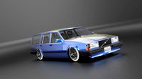
Volvo XC70 Lift Kit and Subframe Spacers (P2 Chassis) by PLaperriere
by Thingiverse
Last crawled date: 3 years ago
This is for the NON NIVOMAT suspension!
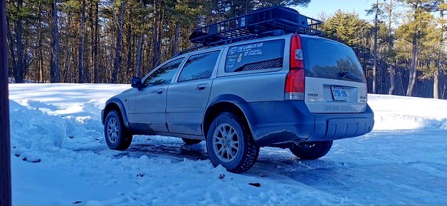
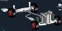
This should lift your P2 Chassis XC70 2-4" depending on the mix of parts you use. The subframe spacers and front tophat spacers fit a P2 XC90 as well. I do not have a way to lift the rear of an XC90 however as I have not been able to design parts for that yet. Here are some examples of expected results:
Top hat spacers only;
Gain 1.75-2" of lift. Mine are 25mm, for example, the Cross Country Performance kit uses 30mm thick spacers so you could modify the height in the Z-Axis in your slicer to potentially get 2.5" of lift from the tophat spacers alone.
Rear spring spacers only and front XC90 V8 front springs;
2'' of lift
Both the tophat spacers and spring spacer/xc90 spring combo;
4-5" of lift from the ground to the top of the wheel arch and approx. 3" more ground clearance. Anything above 2" you will want to do the subframe spacers as well to correct your CV angles. I can confirm with either (or both together) you will be able to fit 225/70/16 tires, I have heard 225/75/16 may fit with trimming of plastics but have not confirmed yet.
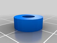
Spring Spacers;
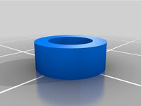
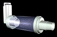
The rear spring spacer will fit underneath the bottom of the rear springs. They provide approximately 1.75"-2" (44.5-50.8mm) of lift in the rear. Using V2 which is slightly taller should net more like 2-2.5" (50.8-66mm) of lift. Pair with V8 XC90 ( P2 Chassis, V8 Models started as of 2006+, OEM Part #30648140 ) front springs on the stock XC70 struts in the front to lift the front 2" as well. If you've got old worn-out springs I recommend printing the V2 spacer. Use the original with either new or heavy-duty springs.
Paired with a set of top hat spacers (also included in the files) this kit could lift your car up to 5" over stock, gaining 3" of ground clearance on 225/70/16 tires. We measured 29" from the ground to the top of the fender arches stock and finished at 33-34"
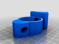
Top Hat Spacers
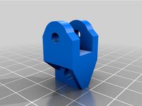
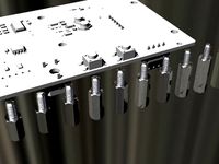
The front top hat spacer is to go in between the top of the front suspension and the strut mount to lift the suspension. The height of the spacer is 1inch (25.4mm) and gives approx. 2" (50.8mm) of lift, the thickness is 1/2x the lift height, you can use this to scale the height as needed to acquire the desired lift. I do not recommend going past 1.5 inches (38mm) as it may put too much strain on the suspension geometry. The Cross Country Performance spacers are 30mm thick. To install, simply remove the factory studs (I used a small socket underneath the tophat and hammered the stud) and then replace with either a bolt, or find a stud that fits your needs. The factory stud is a M8-1.25 x 25mm stud, for a 1'' (25.4mm) spacer you would need a M8-1.25 x 50mm stud. I have also included a 1:1 scale printable copy that you can use to trace out and cut on whatever material you like. The holes are already oversized to account for differences in parts and make installation easier.
The rear tophat spacer is also included in the files. I, unfortunately, do not remember what the sizes for the rear bolts were (1 through the trunk compartment floor and 2 up into the chassis from underneath) are. There are 2 models to choose from, A full-size 1 piece unit and a version a broke into 2 pieces using a dovetail joint for smaller printers. The 2 piece model will need supports to print the dovetails properly, split the model apart and print one at a time if needed. Once it is printed remove the supports and test fit them together, glue is not necessary on the joint but better to be safe than sorry Note it seems that using Cura it is difficult to split apart, when uploading to Prusaslicer it can be split to objects, if using Cura you may need to use modeling software to make 2 separate pieces as separate stls. I also included a spacer to use if you wish to also use the 3rd top bolt that goes through the inside of the body, although the CCP kits online do not reuse that mount after installing the spacer so I assume it is not necessary.
If you use the printable pdf to trace onto your own media, make sure that the settings for the printer are A4 Paper 100% scale. For the front set, the center hole should measure 75mm (Approx 3") and the 3 smaller holes 14mm (Approx 5/8") The whole thing should be 148x134mm (approx. 5 7/8"x5 1/3") For the rear, the holes should be 22mm wide on the short side and again printed on A4 paper.
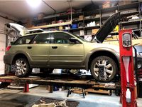
Subframe Drop/Spacers
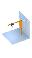
Also included, is a set of files for a 1" (25.4mm) subframe drop (effectively a body lift on this chassis). This will correct the CV angles of the driveshafts after doing a suspension lift. As for other thicknesses of spacers; 1/2" (12.7mm) works with the stock bolts and I have heard 5/8" (15.87mm) would as well but have not confirmed.
Bolts needed for subframe spacers (I recommend either class 8.8 or 10.9 Zinc plated bolts)ONLY NEEDED IF YOU GO OVER 1/2 THICK:
Front Subframe:
4- M14-2.00 120mm bolts (stock is 100mm, and are 18m longer than necessary)
4- M10-1.50 60mm bolts (stock is 40mm, these are the smaller bolts for the jack
pad on the rearward front mount 2 per side)
Rear Subframe:
4- M12-1.75 120mm bolts (stock is 100mm and are 18mm longer than necessary)
I have included a PDF file indicating Bolt size and placement on the subframes
you can reuse the smaller jackpad bolts with some large washers (10mm thick,
you can use less depending on the thickness of subframe spacers you use)
If you're looking to make the subframe spacers yourself out of some other material, here are the measurements, the thickness of the material will determine if you need longer bolts or not:
2 - 3" OD x 1" ID (front Passenger)
2 - 3" OD x 1 1/4" ID (Front Driver)
4 - 2" OD x 3/4" ID (Front Jack Plates, rearward mount)
4 - 3" OD x 3/4" ID (Rear)
*Rear Jackplates (Frontward Mount) will need large washers and reuse the stock bolts,
we found that 10mm worth of washers for 25.4mm spacers worked well
I recommend using 10perimeters, 50% infill, 15 solid top, and bottom layers, 0.3mm resolution with 0.65mm extrusion width. The spacer for the springs needs to be printed with supports on the build plate.
Disclaimer
Due to factors beyond my control, I cannot guarantee against improper use or unauthorized modifications of this information. I assume no liability for property damage or injury incurred as a result of any of the information contained in this post. Use this information at your own risk. I recommend safe practices when working on vehicles and/or with any tools needed to do said work. Due to factors beyond my control, no information contained in this post shall create any expressed or implied warranty or guarantee of any particular result. YOUR MILEAGE MAY VARY. Any injury, damages, or loss that may result from improper use of the tools, equipment, or these files and this post is the sole responsibility of the user and not myself.
This should lift your P2 Chassis XC70 2-4" depending on the mix of parts you use. The subframe spacers and front tophat spacers fit a P2 XC90 as well. I do not have a way to lift the rear of an XC90 however as I have not been able to design parts for that yet. Here are some examples of expected results:
Top hat spacers only;
Gain 1.75-2" of lift. Mine are 25mm, for example, the Cross Country Performance kit uses 30mm thick spacers so you could modify the height in the Z-Axis in your slicer to potentially get 2.5" of lift from the tophat spacers alone.
Rear spring spacers only and front XC90 V8 front springs;
2'' of lift
Both the tophat spacers and spring spacer/xc90 spring combo;
4-5" of lift from the ground to the top of the wheel arch and approx. 3" more ground clearance. Anything above 2" you will want to do the subframe spacers as well to correct your CV angles. I can confirm with either (or both together) you will be able to fit 225/70/16 tires, I have heard 225/75/16 may fit with trimming of plastics but have not confirmed yet.
Spring Spacers;
The rear spring spacer will fit underneath the bottom of the rear springs. They provide approximately 1.75"-2" (44.5-50.8mm) of lift in the rear. Using V2 which is slightly taller should net more like 2-2.5" (50.8-66mm) of lift. Pair with V8 XC90 ( P2 Chassis, V8 Models started as of 2006+, OEM Part #30648140 ) front springs on the stock XC70 struts in the front to lift the front 2" as well. If you've got old worn-out springs I recommend printing the V2 spacer. Use the original with either new or heavy-duty springs.
Paired with a set of top hat spacers (also included in the files) this kit could lift your car up to 5" over stock, gaining 3" of ground clearance on 225/70/16 tires. We measured 29" from the ground to the top of the fender arches stock and finished at 33-34"
Top Hat Spacers
The front top hat spacer is to go in between the top of the front suspension and the strut mount to lift the suspension. The height of the spacer is 1inch (25.4mm) and gives approx. 2" (50.8mm) of lift, the thickness is 1/2x the lift height, you can use this to scale the height as needed to acquire the desired lift. I do not recommend going past 1.5 inches (38mm) as it may put too much strain on the suspension geometry. The Cross Country Performance spacers are 30mm thick. To install, simply remove the factory studs (I used a small socket underneath the tophat and hammered the stud) and then replace with either a bolt, or find a stud that fits your needs. The factory stud is a M8-1.25 x 25mm stud, for a 1'' (25.4mm) spacer you would need a M8-1.25 x 50mm stud. I have also included a 1:1 scale printable copy that you can use to trace out and cut on whatever material you like. The holes are already oversized to account for differences in parts and make installation easier.
The rear tophat spacer is also included in the files. I, unfortunately, do not remember what the sizes for the rear bolts were (1 through the trunk compartment floor and 2 up into the chassis from underneath) are. There are 2 models to choose from, A full-size 1 piece unit and a version a broke into 2 pieces using a dovetail joint for smaller printers. The 2 piece model will need supports to print the dovetails properly, split the model apart and print one at a time if needed. Once it is printed remove the supports and test fit them together, glue is not necessary on the joint but better to be safe than sorry Note it seems that using Cura it is difficult to split apart, when uploading to Prusaslicer it can be split to objects, if using Cura you may need to use modeling software to make 2 separate pieces as separate stls. I also included a spacer to use if you wish to also use the 3rd top bolt that goes through the inside of the body, although the CCP kits online do not reuse that mount after installing the spacer so I assume it is not necessary.
If you use the printable pdf to trace onto your own media, make sure that the settings for the printer are A4 Paper 100% scale. For the front set, the center hole should measure 75mm (Approx 3") and the 3 smaller holes 14mm (Approx 5/8") The whole thing should be 148x134mm (approx. 5 7/8"x5 1/3") For the rear, the holes should be 22mm wide on the short side and again printed on A4 paper.
Subframe Drop/Spacers
Also included, is a set of files for a 1" (25.4mm) subframe drop (effectively a body lift on this chassis). This will correct the CV angles of the driveshafts after doing a suspension lift. As for other thicknesses of spacers; 1/2" (12.7mm) works with the stock bolts and I have heard 5/8" (15.87mm) would as well but have not confirmed.
Bolts needed for subframe spacers (I recommend either class 8.8 or 10.9 Zinc plated bolts)ONLY NEEDED IF YOU GO OVER 1/2 THICK:
Front Subframe:
4- M14-2.00 120mm bolts (stock is 100mm, and are 18m longer than necessary)
4- M10-1.50 60mm bolts (stock is 40mm, these are the smaller bolts for the jack
pad on the rearward front mount 2 per side)
Rear Subframe:
4- M12-1.75 120mm bolts (stock is 100mm and are 18mm longer than necessary)
I have included a PDF file indicating Bolt size and placement on the subframes
you can reuse the smaller jackpad bolts with some large washers (10mm thick,
you can use less depending on the thickness of subframe spacers you use)
If you're looking to make the subframe spacers yourself out of some other material, here are the measurements, the thickness of the material will determine if you need longer bolts or not:
2 - 3" OD x 1" ID (front Passenger)
2 - 3" OD x 1 1/4" ID (Front Driver)
4 - 2" OD x 3/4" ID (Front Jack Plates, rearward mount)
4 - 3" OD x 3/4" ID (Rear)
*Rear Jackplates (Frontward Mount) will need large washers and reuse the stock bolts,
we found that 10mm worth of washers for 25.4mm spacers worked well
I recommend using 10perimeters, 50% infill, 15 solid top, and bottom layers, 0.3mm resolution with 0.65mm extrusion width. The spacer for the springs needs to be printed with supports on the build plate.
Disclaimer
Due to factors beyond my control, I cannot guarantee against improper use or unauthorized modifications of this information. I assume no liability for property damage or injury incurred as a result of any of the information contained in this post. Use this information at your own risk. I recommend safe practices when working on vehicles and/or with any tools needed to do said work. Due to factors beyond my control, no information contained in this post shall create any expressed or implied warranty or guarantee of any particular result. YOUR MILEAGE MAY VARY. Any injury, damages, or loss that may result from improper use of the tools, equipment, or these files and this post is the sole responsibility of the user and not myself.
Similar models
thingiverse
free

Tamiya Semi Truck Suspension Spacer by zanthrax
...ifications.
the stock u-bolt have some thread left over in the rear, for the front you will need to supply 8 regular m3 locknuts.
grabcad
free

Subaru Impreza Lift kit
... lift kit for aluminium casting, the cast came out well. pics are the the pla lift kit model and the cast aluminium (unpolished).
grabcad
free

Jeep TJ 2" Coil Spring Spacer
...jeep tj 2" coil spring spacer
grabcad
coil spring spacer, 2" front or rear jeep tj
thingiverse
free
Ender 3 and Ender 3 V2 extruder spring spacers/compressors by ReDaLeRt
...nsion for your particular needs.
the fusion 360 file is attached, if needed to custom fit these spacers for your particular case.
thingiverse
free
2006 subaru outback lift 2.5i 1 3/4"front 2" rear lift
...umps in the rear, i feel like it's my old bushings that have 160k on them they are vary worn out but it's not to badbolts
thingiverse
free
wltoys 104311 suspension lift upgrade - more flex by alwaysbroke
...own 90 degrees to print. i printed in petg for strength, but pla may work fine for these, it's a pretty light duty toy truck.
thingiverse
free

Flexible Solar Panel Mount by mrjadkowski
...plication.
print these upside down (i.e. you should be able to see the hex-shaped inset for the bolt head on top when you print).
thingiverse
free

Spring Loaded CD Mount Tablet Holder by jmf
...ng around, trim as needed, i also used some ca on the pin to keep it from falling out.
this mount works great on a table top too.
grabcad
free

20 1/2" Double Eye Leaf Spring - 4 Leaves 1 3/4" Wide
...aves: 4
spring width: 1 3/4"
overall length: 21 3/4"
center of eye to center of eye: 20 1/2"
thickness: 1/4"
thingiverse
free
Ender 3 leveling washer
...should help beginners that are having the issue of the bed coming out of level during a print.
feel free to remix for your needs.
Plaperriere
thingiverse
free

Notre Première Pandémie Ornement - Our First Pandemic Ornament by PLaperriere
...notre première pandémie ornement - our first pandemic ornament by plaperriere
thingiverse
notre première pandémie
thingiverse
free

Blue Sea Systems 250A Bus Bar Cover by PLaperriere
...s as well. covers 5/16' studs
https://www.amazon.ca/gp/product/b006velfdk/ref=ppx_yo_dt_b_asin_title_o02_s00?ie=utf8&th=1
thingiverse
free

Deadbolt Door Lock Flip Lock by PLaperriere
...ng the screws on the inside plate of the deadbolt, placing the flip lock underneath and putting the screws back and tighten them.
thingiverse
free
Google Home Mini VIVO Monitor Stand Mount by PLaperriere
...%2c185&sr=8-5&th=1
but have also included a model with no hole so you can customise it to fit the hole diameter you need.
thingiverse
free

Victron BMV-712 Battery Monitor Surface Mount Holder by PLaperriere
...or to pass the wire through. no supports or special print parameters are needed. i printed out of petg to be safe for temperature
thingiverse
free

Volvo P2/P80 Subframe Bushing Inserts by PLaperriere
...lt from improper use of the tools, equipment, or these files and this post is the sole responsibility of the user and not myself.
Xc70
3d_ocean
$89

Volvo XC70 2013
...y, in real units of measurement, qualitatively and maximally close to the original. model formats: - *.max (3ds max 2008 scanl...
3d_ocean
$89

Volvo XC70 2011
... in real units of measurement, qualitatively and maximally close to the original. model formats: - *.max (3ds max 2008 scanlin...
3d_export
$99

Volvo XC70 2013 3D Model
...odel
3dexport
volvo xc70 v70 2013 2014 2015 2016 5-door wagon estate 4x4 sweden
volvo xc70 2013 3d model humster3d 83658 3dexport
cg_studio
$89

Volvo xc70 20083d model
...l
cgstudio
.3ds .lwo .max .obj .xsi - volvo xc70 2008 3d model, royalty free license available, instant download after purchase.
cg_studio
$99

Volvo XC70 20133d model
...on
.3ds .c4d .fbx .lwo .max .mb .obj - volvo xc70 2013 3d model, royalty free license available, instant download after purchase.
cg_studio
$99

VOLVO XC70 20143d model
...tudio
.3ds .c4d .fbx .lwo .max .obj - volvo xc70 2014 3d model, royalty free license available, instant download after purchase.
3d_export
$99

Volvo XC70 2011 3D Model
...12 2013 2014 s40 v50 v70 wagon sport luxury sweden van family suv crossover 4x4
volvo xc70 2011 3d model humster3d 39235 3dexport
cg_studio
$99

Volvo XC70 20113d model
...o
.3ds .c4d .fbx .lwo .max .mb .obj - volvo xc70 2011 3d model, royalty free license available, instant download after purchase.
humster3d
$75

3D model of Volvo XC70 2013
...y a detailed 3d model of volvo xc70 2013 in various file formats. all our 3d models were created maximally close to the original.
humster3d
$75

3D model of Volvo XC70 2011
...y a detailed 3d model of volvo xc70 2011 in various file formats. all our 3d models were created maximally close to the original.
Subframe
3d_export
$10

Modern walnut entertainment unit - TV unit
...is made from solid walnut with a dark wood subframe<br>the drawers sections are parented to each drawer fronts so...
thingiverse
free

Pampered Chef - Salt or Pepper Grinder subframe by undertakingyou
...you
thingiverse
replaces the spring bar and female grinder socket (which i am calling the subframe) for a pampered chef grinder.
thingiverse
free

Subframe for Micromake Delta 3D Printer by sidmicious
...cious
thingiverse
to improve the torsional stiffness of a frame.
suit for 20mm width frame.
https://jibundeyarou.com/subframe01/
thingiverse
free

KTM exc 2008-2013 subframe bolt insert by Gonzalo98
...bolt insert with a 5mm hole to add a m6 helicoil.
tope de goma para subchasis de ktm enduro, preparado para meter un helicoil m6.
thingiverse
free
Volvo P2/P80 Subframe Bushing Inserts by PLaperriere
...lt from improper use of the tools, equipment, or these files and this post is the sole responsibility of the user and not myself.
3d_sky
free

Tablets
...tablets 3dsky the tablet subframe with stretched...
thingiverse
free

SKR motherboard & Raspberry Pi subframe for Sidewinder X1 by CafeNoir64
...cam to the pi.
firmware.bin file is configured for skr 1.4 turbo with 5 tmc2209's, settings can be found in the config files.
thingiverse
free

2011-2015 Civic Cap Side Mbr by eccs19
...stones from getting into the hydroformed tube on the subframe i have yet to print and try out...
thingiverse
free

Honda Hobbit Pedal Shaft Bushing by SRickert
...srickert thingiverse honda hobbit pedal shaft bushing for stock subframe. ...
P2
turbosquid
$25

Azev P2
...p2
turbosquid
royalty free 3d model azev p2 for download as on turbosquid: 3d models for games, architecture, videos. (1382603)
3d_export
$59

P2 3D Model
...p2 3d model
3dexport
3d interior
p2 3d model arturrabello 3210 3dexport
turbosquid
$8

P2 lamp
... available on turbo squid, the world's leading provider of digital 3d models for visualization, films, television, and games.
turbosquid
$50

P2- 3D Workingbench
...ee 3d model p2- 3d workingbench for download as ige and sldpr on turbosquid: 3d models for games, architecture, videos. (1245246)
turbosquid
$23

Mountains Snow Enviroment p2
...ree 3d model mountains snow enviroment p2 for download as max on turbosquid: 3d models for games, architecture, videos. (1486802)
3ddd
$1

Gallery / Bolero P2
...gallery / bolero p2
3ddd
gallery
gallery-bolero_p2-45-28-46 high poly
humster3d
$40

3D model of Kitchen Set P2
...uy a detailed 3d model of kitchen set p2 in various file formats. all our 3d models were created maximally close to the original.
turbosquid
$10

Ling P1 P2 H Seeddesign
... 3d model ling p1 p2 h seeddesign for download as max and obj on turbosquid: 3d models for games, architecture, videos. (1568628)
turbosquid
$10

Ling P2 H Seeddesign Gold
...d model ling p2 h seeddesign gold for download as max and obj on turbosquid: 3d models for games, architecture, videos. (1568626)
turbosquid
$10

Ling P2 H Seeddesign Copper
...model ling p2 h seeddesign copper for download as max and obj on turbosquid: 3d models for games, architecture, videos. (1568625)
Volvo
3d_export
free
Volvo 245
...volvo 245
3dexport
old volvo 245
3ddd
free

Volvo S40
...я с volvo 340, затем были модели volvo 440/460 и в настоящее время – это volvo s40/v40. сегодня мы убеждены в том, что совершенно
3d_export
$5

Volvo FH750
...iently and comfort to reduce the load. the flagship of the industry and a real workhorse — this car has become even more perfect.
3d_ocean
$89
Volvo Tractor FM
...m heavy heavy high high industrial industrial tractor tractor truck truck vehicle vehicle volvo volvo
high detailed volvo tractor
turbosquid
$50

Volvo XC90R
...osquid
royalty free 3d model volvo xc90r for download as 3dm on turbosquid: 3d models for games, architecture, videos. (1578353)
turbosquid
$75

Volvo XC60
...oyalty free 3d model volvo xc60 for download as fbx and blend on turbosquid: 3d models for games, architecture, videos. (1280068)
3d_export
$5

Volvo logo 3D Model
...volvo logo 3d model
3dexport
volvo volvo car logo bus new parts truck
volvo logo 3d model dreamextrude 81900 3dexport
3d_export
$5
Volvo 745
...volvo 745
3dexport
3d_export
free

Volvo 240
...volvo 240
3dexport
3d_export
free

volvo 740
...volvo 740
3dexport
Spacers
turbosquid
$55
Spacer
... available on turbo squid, the world's leading provider of digital 3d models for visualization, films, television, and games.
turbosquid
$60

grendizer & double spacer
... available on turbo squid, the world's leading provider of digital 3d models for visualization, films, television, and games.
3d_export
$5
Hex Spacers M3 Male-Female
... spacers m3 male-female
3dexport
hex spacers m3 male-female with length from 5mm to 60mm for printed circuit boards. step files.
3d_export
$5
industrial lift - spacer crane
...crane<br>- 500 kg<br>- render 3ds max 2020 and corona renderer.<br>- formats: max 2020, max 2017, obj, fbx, stp
3d_export
$5

spacer hanging light
...lampshades: any total number of lamps: 6 polys: 18 546 verts: 19 045 https://imperiumloft.ru/lyustry-175/ev_a048924-eurosvet.html
turbosquid
$5
Industrial lift Spacer crane Renaissance construction
...naissance construction for download as max, max, fbx, and obj on turbosquid: 3d models for games, architecture, videos. (1571898)
3d_export
$7

industrial lift - spacer crane renaissance construction
...ction<br>- 750 kg<br>- render 3ds max 2020 and corona renderer.<br>- formats: max 2020, max 2017, obj, fbx, stp
3d_export
$10
Spacer Sliding Wardrobe 1200 Hanger
...painter available for all software<br>ue4. ue5. blender. maya. 3d max. unity. c4d.<br>formats: .obj .gltf .fbx .blend
3d_export
$5

Hockey puck 3D Model
...hockey puck 3d model
3dexport
hockey puck spacer washer disk shim
hockey puck 3d model gizmo_fbi 28754 3dexport
3d_export
$5

Front 30mm Lift Kit for 1996-2004 Nissan Pathfinder and 1997-2003 Infiniti QX4
...terrano r50, regulus 1997-2003 infiniti qx4 - front strut spacers ...
Chassis
design_connected
$16

Chassis
...chassis
designconnected
wilkhahn chassis chairs computer generated 3d model. designed by stefan diez.
3d_export
$10

truck chassis
...truck chassis
3dexport
truck chassis
3d_export
$5
Truck chassis
...truck chassis
3dexport
truck chassis
3d_export
$5

buggy chassi
...buggy chassi 3dexport chassis of a simple ride...
turbosquid
$35

Chassis
...odel chassis for download as 3ds, dxf, obj, c4d, fbx, and stl on turbosquid: 3d models for games, architecture, videos. (1413332)
design_connected
$16

Chassis Armchair
...chassis armchair
designconnected
baxter chassis armchair armchairs computer generated 3d model. designed by n/a.
turbosquid
$25
DRONE CHASSIS
...bosquid
royalty free 3d model drone chassis for download as on turbosquid: 3d models for games, architecture, videos. (1699724)
turbosquid
$79

Car Chassis
...quid
royalty free 3d model car chassis for download as blend on turbosquid: 3d models for games, architecture, videos. (1593376)
turbosquid
$50
Car Chassis
...osquid
royalty free 3d model car chassis for download as dwg on turbosquid: 3d models for games, architecture, videos. (1164087)
turbosquid
$75

Chassis 8x8
...free 3d model chassis 8x8 for download as ige, obj, and sldas on turbosquid: 3d models for games, architecture, videos. (1221250)
Lift
archibase_planet
free
Lift
...lift
archibase planet
lift hoist car lift
lift 1 - 3d model (*.3ds) for interior 3d visualization.
archibase_planet
free

Lift
...lift
archibase planet
lift lifting jack autohoist
lift 2 - 3d model (*.gsm+*.3ds) for interior 3d visualization.
archibase_planet
free
Lift
...lift
archibase planet
lift autohoist car lift hoist
lift 3 - 3d model (*.gsm+*.3ds) for interior 3d visualization.
3d_ocean
$21
Lift
...lift
3docean
crane industrial lift loader machine outdoor work
lifts with building materials
archibase_planet
free
Lift
...lift
archibase planet
lift elevator
lift n050713 - 3d model (*.gsm+*.3ds) for interior 3d visualization.
archibase_planet
free
Lift
...lift
archibase planet
lift autohoist hoist
lift for car n240611 - 3d model (*.3ds) for interior 3d visualization.
archibase_planet
free
Lift
...lift
archibase planet
lift autohoist hoist
lift for car n020711 - 3d model (*.gsm+*.3ds) for interior 3d visualization.
archibase_planet
free
Lift
...lift
archibase planet
autohoist lift hoist
lift car 2 n150111 - 3d model (*.gsm+*.3ds) for interior 3d visualization.
archibase_planet
free
Lift
...lift
archibase planet
car lift car elevator hoist
lift n090709 - 3d model (*.gsm+*.3ds) for interior 3d visualization.
archibase_planet
free
Lift
...lift
archibase planet
lift hoist elevator
lift car 1 n150111 - 3d model (*.gsm+*.3ds) for interior 3d visualization.
Kit
turbosquid
$3

Bathroom Kit Baño kit
... available on turbo squid, the world's leading provider of digital 3d models for visualization, films, television, and games.
turbosquid
$19

Kit
... available on turbo squid, the world's leading provider of digital 3d models for visualization, films, television, and games.
3d_export
$20

Drift Kit
...drift kit
3dexport
turbosquid
$40

BitCoin Kit
...urbosquid
royalty free 3d model bitcoin kit for download as on turbosquid: 3d models for games, architecture, videos. (1519068)
turbosquid
$9

Industrial kit
...osquid
royalty free 3d model industrial kit for download as on turbosquid: 3d models for games, architecture, videos. (1144117)
turbosquid
$6

Kit Vases
...
turbosquid
royalty free 3d model kit vases for download as on turbosquid: 3d models for games, architecture, videos. (1285114)
turbosquid
free
Survival Kit
...rbosquid
royalty free 3d model survival kit for download as on turbosquid: 3d models for games, architecture, videos. (1637721)
turbosquid
$50
Ninja Kit
...rbosquid
royalty free 3d model ninja kit for download as fbx on turbosquid: 3d models for games, architecture, videos. (1672364)
turbosquid
$35

Brushes Kit
...osquid
royalty free 3d model brushes kit for download as max on turbosquid: 3d models for games, architecture, videos. (1216721)
turbosquid
$19
Medical kit
...osquid
royalty free 3d model medical kit for download as fbx on turbosquid: 3d models for games, architecture, videos. (1486089)