Thingiverse
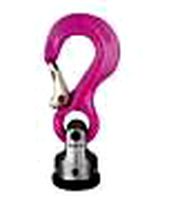
Velux Hook – Sloping Roof Window Handle by Zed42
by Thingiverse
Last crawled date: 2 years, 11 months ago
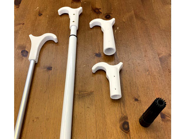
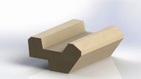
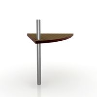
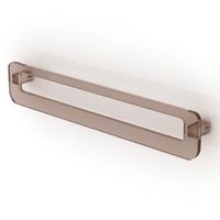
A robust “hook” handle to manage opening and closing of (Velux) sloping roof windows.
The hook is designed to fit an extension (telescopic, paint) pole (originally intended for paint roller) – both with and without the original soft plastic tip and also a round aluminum rod with 15 mm outer diameter.
The hook was designed with intention to absorb rather extensive forces (just in case the window does not move that freely) and is intended for handling opening/closing of the window only. I don’t have any auxiliary accessories like inner shades etc. hence these are ignored for the time being.
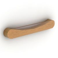
Model A – fits extension pole with the original soft plastic tip on. I.e. the pole goes without any modification except drill through the soft plastic tip in two spots to hold the handle in place. In fact another drill & screw tightening might be needed to keep the plastic tip in place since it is originally only glued atop of the pole however downward forces when opening the window may soon wear the glue out.
The extension pole itself is sold in hobby market(s) – German-headquartered Hornbach in my case – and the original soft plastic tip measures are: bottom diameter = 30 mm, top diameter = 23 mm, length = 120 mm.
Model A is round and appears rather bulky given the size of the soft plastic tip it’s got to swallow.
Model B – just like Model A also Model B fits an extension rod however this time without the original soft plastic tip, i.e. expects evenly round profile of 21 mm in diameter.
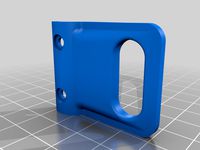
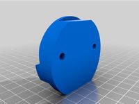
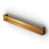
Model C – is designed to sit atop of 15 mm aluminum round rod. Since the rod is expected to be hollow a bottom Cap is provided alongside of this version.
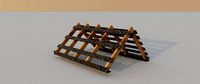
Printing and usage: the hook handles look better when printed standing - however layers in that case have to resist the strongest forces as they are perpendicular to the direction of pull / push force. So I prefer to print them lying horizontally on printer bed.
I myself was printing in 0.3 mm resolution with 9 outline/perimeter shells with 60% infill. The positive effect of several outline/perimeter shells is in particular noticeable with Model C – which is the only model designed as squared on the outside so it prints well in horizontal position. Since this model is rather subtle (compared to A & B) the square outside shape looks & prints well lying on printer build platform. Outline/perimeter shells run alongside of entire shape uninterrupted thus giving good resistance to push/pull force of the print.
The rounded shapes of Model A and B need outer supports (definitely model A as it is also conic) when printing horizontally. When printing inside with supports (recommendable since the inner shape is round also for Model C) I manually removed a row of supports every 10 – 20 mm. In that way I could easily push them in to disengage before pulling them out and the support gaps were easily bridged. Only inside supports needed in case of model C.
The hook is designed to fit an extension (telescopic, paint) pole (originally intended for paint roller) – both with and without the original soft plastic tip and also a round aluminum rod with 15 mm outer diameter.
The hook was designed with intention to absorb rather extensive forces (just in case the window does not move that freely) and is intended for handling opening/closing of the window only. I don’t have any auxiliary accessories like inner shades etc. hence these are ignored for the time being.
Model A – fits extension pole with the original soft plastic tip on. I.e. the pole goes without any modification except drill through the soft plastic tip in two spots to hold the handle in place. In fact another drill & screw tightening might be needed to keep the plastic tip in place since it is originally only glued atop of the pole however downward forces when opening the window may soon wear the glue out.
The extension pole itself is sold in hobby market(s) – German-headquartered Hornbach in my case – and the original soft plastic tip measures are: bottom diameter = 30 mm, top diameter = 23 mm, length = 120 mm.
Model A is round and appears rather bulky given the size of the soft plastic tip it’s got to swallow.
Model B – just like Model A also Model B fits an extension rod however this time without the original soft plastic tip, i.e. expects evenly round profile of 21 mm in diameter.
Model C – is designed to sit atop of 15 mm aluminum round rod. Since the rod is expected to be hollow a bottom Cap is provided alongside of this version.
Printing and usage: the hook handles look better when printed standing - however layers in that case have to resist the strongest forces as they are perpendicular to the direction of pull / push force. So I prefer to print them lying horizontally on printer bed.
I myself was printing in 0.3 mm resolution with 9 outline/perimeter shells with 60% infill. The positive effect of several outline/perimeter shells is in particular noticeable with Model C – which is the only model designed as squared on the outside so it prints well in horizontal position. Since this model is rather subtle (compared to A & B) the square outside shape looks & prints well lying on printer build platform. Outline/perimeter shells run alongside of entire shape uninterrupted thus giving good resistance to push/pull force of the print.
The rounded shapes of Model A and B need outer supports (definitely model A as it is also conic) when printing horizontally. When printing inside with supports (recommendable since the inner shape is round also for Model C) I manually removed a row of supports every 10 – 20 mm. In that way I could easily push them in to disengage before pulling them out and the support gaps were easily bridged. Only inside supports needed in case of model C.
Similar models
thingiverse
free

Velux Hook – Sloping Roof Window Handle by Zed42
...in to disengage before pulling them out and the support gaps were easily bridged. only inside supports needed in case of model c.
thingiverse
free

Velux hook roof window rooflight reinforced by matter13
...t reinforced by matter13
thingiverse
reinforced the window hook to make it stronger and easier to print flat with fewer supports
thingiverse
free

Velux hook by nyx_4
...he adaptator you can use a 20mm or 18mm. thanks to the 3 screw systeme you can surely use a smaller handle and tighten a bit more
thingiverse
free

Shader hook for VELUX skylight windows by Hejzenberg
...ook for velux skylight windows by hejzenberg
thingiverse
replacement window shader hook for velux or any other skylight windows.
thingiverse
free

Hook Velux Roof Windows, by franic
...hook velux roof windows, by franic
thingiverse
hook for the opening and closing bar of a velux brand roof window.
thingiverse
free

Fishing rod replacement tip by paulschonfeld
...erse
this print will replace the tip of a broken fishing rod. the existing stl will fit around a rod that is 2.9 mm in diameter.
thingiverse
free

Tent-Pole Coat Hook by gjodink
...tent-pole coat hook by gjodink
thingiverse
tent-pole coat hook, 23 mm pole diameter
thingiverse
free

Tea Towel Kitchen Multi-hook (20mm) by Mickice
...meter round handles
10~mm big gap
2~mm small gap
pro-tip: ensure you have a good first layer to prevent sharp edges / scratching.
thingiverse
free

Window Stop for velux handle by andyinfrance
...window stop for velux handle by andyinfrance
thingiverse
locks the velux window partly open to let air in.
thingiverse
free

Ergonomic Velux hook by Backmann
...ound.
now it is possible to print this amazing tool on a small printer like the mini fabrikator with a print bed of only 80x80mm.
Zed42
thingiverse
free

Cable Port in 60mm Desk Grommet by Zed42
... a long one with several options hence giving more freedom e.g. for shorter cables while maintaining the same overall rod length.
thingiverse
free
Velux Hook – Sloping Roof Window Handle by Zed42
...in to disengage before pulling them out and the support gaps were easily bridged. only inside supports needed in case of model c.
Velux
3ddd
$1

Мансардное окно Velux
...ардное окно velux
3ddd
окно , velux
мансардное окно velux, может открываться, 1600 polys
thingiverse
free
Velux
...velux
thingiverse
velux sparepart
3d_sky
free

Mansard Windows Velux
...mansard windows velux
3dsky
mansard windows velux, can be opened, 1600 polys
thingiverse
free

Velux Dachfenster Jalousie by GHennrich
...velux dachfenster jalousie by ghennrich
thingiverse
velux dachfenster jalousie
thingiverse
free

Holder for VELUX remote by thingfisch
...holder for velux remote by thingfisch
thingiverse
holder for velux remote
thingiverse
free

Velux VK Verschluss by kadrim
...velux vk verschluss by kadrim
thingiverse
replacement part for velux vk windows
thingiverse
free

Velux Window-Holder by Spider69
...velux window-holder by spider69
thingiverse
velux roof window holder, mounted on the sidewall.
thingiverse
free
Old Velux Strike / Recepteur de serrure pour ancien Velux by richard_8442
... window.
juste une copie des anciennes gâches / receveur de serrure velux. elle a été copié à partir d'un velux ghl4 de 1985.
thingiverse
free

Crochet Velux by yo_yo
...50% infill for robustness
crochet pour fenêtre de toit velux.
imprimé avec des parois de 3mm et 50% infill pour plus de solidité.
thingiverse
free

Velux Part by lordpositron
...sitron
thingiverse
this 3d model can replace ves/v21 velux part.
i printed this with a creality ender 3 pro and a pla filament.
Sloping
design_connected
$11

Slope
...slope
designconnected
miniforms slope computer generated 3d model. designed by skrivo.
3ddd
$1
Pendant lamp SLOPE
...pendant lamp slope
3ddd
slope
pendant lamp slope
3ddd
$1

Italux slope md9193
...italux slope md9193
3ddd
italux
italux slope md9193
turbosquid
$15
slope stone
...osquid
royalty free 3d model slope stone for download as stl on turbosquid: 3d models for games, architecture, videos. (1666168)
3d_export
$9

cameron slope
...cameron slope
3dexport
turbosquid
$12

Sloping armchair
... available on turbo squid, the world's leading provider of digital 3d models for visualization, films, television, and games.
3ddd
free
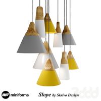
Slope Lamp by Skrivo Design
... miniforms , skrivo design
потолочные подвесные светильники "slope"
3d_export
$30
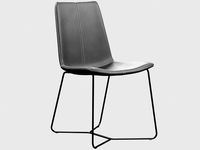
slope chair west elm
...slope chair west elm
3dexport
slope chair west elm max fbx obj
turbosquid
$20

House 2x2 slope
...lty free 3d model house 2x2 slope for download as obj and fbx on turbosquid: 3d models for games, architecture, videos. (1278517)
3d_export
$5

snow slope lowpoly
...snow slope lowpoly
3dexport
Hook
turbosquid
$11

Hooked hooks
... 3d model hooked hooks for download as max, obj, fbx, and stl on turbosquid: 3d models for games, architecture, videos. (1629361)
archibase_planet
free

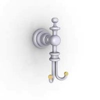
Hook
...hook
archibase planet
coatrack hook peg
hook - 3d model (*.gsm+*.3ds) for interior 3d visualization.
archibase_planet
free

Hook
...hook
archibase planet
coatrack stand hook
hook - 3d model (*.gsm+*.3ds) for interior 3d visualization.
archibase_planet
free

Hook
...hook
archibase planet
coatrack hook peg
hook - 3d model (*.gsm+*.3ds) for interior 3d visualization.
archibase_planet
free
Hook
...hook
archibase planet
hook bathroom ware
hook - 3d model (*.gsm+*.3ds) for interior 3d visualization.
turbosquid
$14

Hook
...ok
turbosquid
royalty free 3d model hook for download as c4d on turbosquid: 3d models for games, architecture, videos. (1436676)
3d_export
$10

butcher hooks
...butcher hooks
3dexport
butcher hooks
3d_export
$5
nut hook
...nut hook
3dexport
nut hook
3d_export
$5

rope hook
...rope hook
3dexport
rope hook
3d_export
$5

j hook
...j hook
3dexport
j hook
Roof
3ddd
$1

Roof
...roof
3ddd
kare , roof
kare кресло roof.
archibase_planet
free
Roof
...roof
archibase planet
roof iron roof
fence roof - 2 - 3d model (*.gsm+*.3ds) for interior 3d visualization.
archibase_planet
free
Roof
...roof
archibase planet
roof iron roof
fence roof-3 - 3d model (*.gsm+*.3ds) for interior 3d visualization.
archibase_planet
free
Roof
...roof
archibase planet
roof iron roof
fence roof-5 - 3d model (*.gsm+*.3ds) for interior 3d visualization.
archibase_planet
free
Roof
...roof
archibase planet
roof iron roof
fence roof-6 - 3d model (*.gsm+*.3ds) for interior 3d visualization.
archibase_planet
free

Roof
...roof
archibase planet
roof iron roof
fence roof-1- 3d model (*.gsm+*.3ds) for interior 3d visualization.
3d_export
free
roof
...roof
3dexport
roof construct
archibase_planet
free
Roof
...roof
archibase planet
roof skylight
fence roof-7 - 3d model (*.gsm+*.3ds) for interior 3d visualization.
archibase_planet
free

Roof
...roof
archibase planet
roof skylight
fence roof-8 - 3d model (*.gsm+*.3ds) for interior 3d visualization.
archibase_planet
free

Roof
...roof
archibase planet
roof house-top
roof n070211 - 3d model (*.gsm+*.3ds) for exterior 3d visualization.
Handle
archibase_planet
free
Handle
...handle
archibase planet
handle furniture handle
handle 1 - 3d model (*.gsm+*.3ds) for interior 3d visualization.
archibase_planet
free
Handle
...handle
archibase planet
handle furniture handle
handle 5 - 3d model (*.gsm+*.3ds) for interior 3d visualization.
archibase_planet
free

Handle
...handle
archibase planet
handle furniture handle
handle 3 - 3d model (*.gsm+*.3ds) for interior 3d visualization.
archibase_planet
free
Handle
...handle
archibase planet
handle furniture handle
handle 6 - 3d model (*.gsm+*.3ds) for interior 3d visualization.
archibase_planet
free
Handle
...handle
archibase planet
handle furniture handle
handle 4 - 3d model (*.gsm+*.3ds) for interior 3d visualization.
archibase_planet
free

Handle
...handle
archibase planet
handle furniture handle
handle 2 - 3d model (*.gsm+*.3ds) for interior 3d visualization.
archibase_planet
free
Handle
...handle
archibase planet
handle furniture handle knob
handle 2 n140814 - 3d model (*.gsm+*.3ds) for interior 3d visualization.
archibase_planet
free

Handle
...handle
archibase planet
handle door knob door-handle
handle n110413 - 3d model (*.gsm+*.3ds) for interior 3d visualization.
archibase_planet
free

Handle
...handle
archibase planet
door-handle handle door-knob
handle n070209 - 3d model (*.gsm+*.3ds) for interior 3d visualization.
archibase_planet
free
Handle
...handle
archibase planet
door-handle handle door-knob
handle n270309 - 3d model (*.gsm+*.3ds) for interior 3d visualization.
Window
3d_ocean
$3

Window
...window
3docean
window
a lowpoly window .
3d_ocean
$2
Window
...window
3docean
window
a lowpoly window.
3d_ocean
$2

Window
...window
3docean
window
a lowpoly window.
3d_ocean
$2
Window
...window
3docean
window
a lowpoly window .
3d_ocean
$5
Window
...window
3docean
window
a high quality window.
3d_ocean
$4
Window
...window
3docean
window
a high quality window.
3d_ocean
$4

Window
...window
3docean
window
a high quality window.
3d_ocean
$4
Window
...window
3docean
window
a high quality window.
3d_ocean
$3

Window
...window
3docean
window
a high quality window.
3d_ocean
$3
Window
...window
3docean
window
a high quality window .