Thingiverse

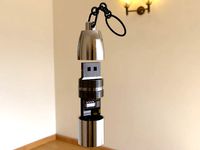
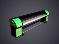
USB Powered Printer Lighting for Lulzbot Mini (or others) Using Eveready LED Flashlight by hemocyanin
by Thingiverse
Last crawled date: 3 years ago
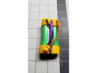
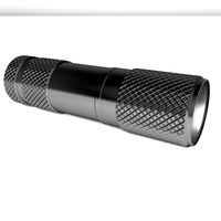
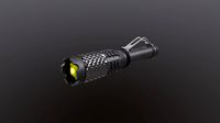
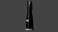
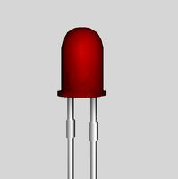
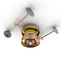
I have many Eveready 6v flashlights because the price of a battery/flashlight combo ($4.97), is only 29 cents more than the cost of a battery alone ($4.68) at my local Home Depot (FN1). It's really hard to force myself to not buy the combo even though I've got these things coming out my ears by now and I almost always break down and just buy the combo. I've finally found a use for some of my dead flashlights: cheap lighting for my printer!
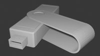
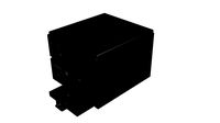
Basically, for 29 cents I get some LEDs and resistors soldered to a board already drilled with mounting holes, a button, and an unbreakable beer mug (not really of course, I doubt the plastic is food grade). The only other non-printed part needed is one of the many now useless mini-USB cords I have sitting in a box because nothing uses those anymore.
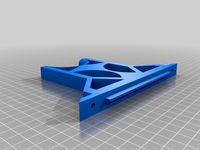
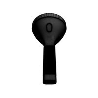
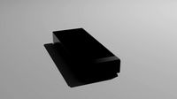
I've uploaded the files in STL and FreeCAD native file format. If you don't have a printer like mine, but do have a stack of these flashlights, I've also included just the button mount for the Eveready button which you can attach to something made for your printer. When printed sideways with the supports in place, the button fits in nice and snug because of the fine bits of support material left over -- you could get away with using no glue to hold it in place. If printed on its back, no support is needed, but you'll probably need glue or epoxy.
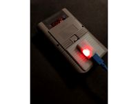
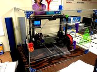
My example is printed in natural ABS on a Lulzbot Mini, Cura basic settings, normal (med) quality.
--- assembly instructions (FN2) ---
Removing the LED board: the first thing to do is grab the large conductive ring at the base of the flashilight head, cut through the plastic supports and attachment bits, and break that off. The board isn't screwed down -- instead little melted plastic posts hold it in place. A few snips will allow you to wiggle it free. You'll see where positive and negative get attached -- take a mental note and clip off the positive wire (negative is just a contact spring).
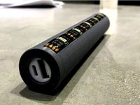
Removing the button: the button is held in place by friction, not a nut. First, remove the rubber weather boot by pulling it off (again, not screwed down). Then, using a flathead screwdriver or something similar, from the inside of the flahslight body pry the switch body down through the hole. It kind of helps to pry along the vertical walls too. You can also try pounding it down through the hole from outside the flashlight body. If you try to use pliers to pull on the switch body from the inside, it will probably split in half, the spring will go sprong and dissapear from the face of the earth, and you won't have a button. Just keep prying with the screwdriver or bash it through. This will take a bit of force, but it'll squeeze out eventually.
Sacrificing mini-USB cord: snip off the useless end, strip outer insulation. Almost certainly, pos and neg will correspond to red and black wires. You can always plug it in and test to be certain. Snip back the data wires, shielding, and anything else (different levels is nice to make shorting almost impossible), leaving just the positive and negative wires. Strip those a little -- red should be pretty short and black fairly long (red will go to one pole of the switch, black to the LED board.
Final Assembly: Break off the four tabs in the button box of the printed part, then feed the USB wire through a hole in the button box of the printed part from outside to inside. Solder the red wire to one pole of the button, then solder another length of wire to the other pole of the button. If the USB cord is loose in its hole, you can add some tape to wedge it in there and it wouldn't hurt to tape over the poles of the switch to prevent anything accidentally running down the USB data lines. Feed the loose positive and negative lines out through another hole, and then slide the button into place. Now you can solder the positive and negative leads to the LED board: red to the positive terminal of the LED board, and black to the negative (big circular pad in the center). The board can then be mounted to the printed bracket with a small screw (FN3).
--- Footnotes ---
FN1: Flashlight/battery combo -- Just the battery. Ridiculous 29 cent difference in price.
FN2: this is for the older 3 LED version. New versions of this flashlight in the store have a single LED. I'm sure it isn't rocket science to get that one out either, but I'm going to wait till the batteries die in my newer flashlights before breaking them down.
FN3: I bought a 1000 of these screws and they're very useful: http://www.amazon.com/gp/product/B00GMQDSRI (I'm not trying to flog this product or push the particular seller -- it just took me forever to find some reasonably priced tiny screws and I spent a lot of money on things that turned out to not be what I wanted, so I thought the link might be useful). If you have different size screws, you can always drill the hole out to make use of whatever you have on hand.
Basically, for 29 cents I get some LEDs and resistors soldered to a board already drilled with mounting holes, a button, and an unbreakable beer mug (not really of course, I doubt the plastic is food grade). The only other non-printed part needed is one of the many now useless mini-USB cords I have sitting in a box because nothing uses those anymore.
I've uploaded the files in STL and FreeCAD native file format. If you don't have a printer like mine, but do have a stack of these flashlights, I've also included just the button mount for the Eveready button which you can attach to something made for your printer. When printed sideways with the supports in place, the button fits in nice and snug because of the fine bits of support material left over -- you could get away with using no glue to hold it in place. If printed on its back, no support is needed, but you'll probably need glue or epoxy.
My example is printed in natural ABS on a Lulzbot Mini, Cura basic settings, normal (med) quality.
--- assembly instructions (FN2) ---
Removing the LED board: the first thing to do is grab the large conductive ring at the base of the flashilight head, cut through the plastic supports and attachment bits, and break that off. The board isn't screwed down -- instead little melted plastic posts hold it in place. A few snips will allow you to wiggle it free. You'll see where positive and negative get attached -- take a mental note and clip off the positive wire (negative is just a contact spring).
Removing the button: the button is held in place by friction, not a nut. First, remove the rubber weather boot by pulling it off (again, not screwed down). Then, using a flathead screwdriver or something similar, from the inside of the flahslight body pry the switch body down through the hole. It kind of helps to pry along the vertical walls too. You can also try pounding it down through the hole from outside the flashlight body. If you try to use pliers to pull on the switch body from the inside, it will probably split in half, the spring will go sprong and dissapear from the face of the earth, and you won't have a button. Just keep prying with the screwdriver or bash it through. This will take a bit of force, but it'll squeeze out eventually.
Sacrificing mini-USB cord: snip off the useless end, strip outer insulation. Almost certainly, pos and neg will correspond to red and black wires. You can always plug it in and test to be certain. Snip back the data wires, shielding, and anything else (different levels is nice to make shorting almost impossible), leaving just the positive and negative wires. Strip those a little -- red should be pretty short and black fairly long (red will go to one pole of the switch, black to the LED board.
Final Assembly: Break off the four tabs in the button box of the printed part, then feed the USB wire through a hole in the button box of the printed part from outside to inside. Solder the red wire to one pole of the button, then solder another length of wire to the other pole of the button. If the USB cord is loose in its hole, you can add some tape to wedge it in there and it wouldn't hurt to tape over the poles of the switch to prevent anything accidentally running down the USB data lines. Feed the loose positive and negative lines out through another hole, and then slide the button into place. Now you can solder the positive and negative leads to the LED board: red to the positive terminal of the LED board, and black to the negative (big circular pad in the center). The board can then be mounted to the printed bracket with a small screw (FN3).
--- Footnotes ---
FN1: Flashlight/battery combo -- Just the battery. Ridiculous 29 cent difference in price.
FN2: this is for the older 3 LED version. New versions of this flashlight in the store have a single LED. I'm sure it isn't rocket science to get that one out either, but I'm going to wait till the batteries die in my newer flashlights before breaking them down.
FN3: I bought a 1000 of these screws and they're very useful: http://www.amazon.com/gp/product/B00GMQDSRI (I'm not trying to flog this product or push the particular seller -- it just took me forever to find some reasonably priced tiny screws and I spent a lot of money on things that turned out to not be what I wanted, so I thought the link might be useful). If you have different size screws, you can always drill the hole out to make use of whatever you have on hand.
Similar models
thingiverse
free

Mini flashlight by VyacheslavSS
...de of the led is bent over the positive side of the battery and is clamped by the cover. fixation with m3 or self-tapping screws.
thingiverse
free
18650 holder 1S / 2S
...make sure they are correctly oriented. 1s instructions follow similar steps as described in the2s construction, however: solder two...
thingiverse
free

Flashlight by Goldeagle_54321
...rts i had.
!!!
instead of the bredboard wires i used to connect the lipo you can just solder the cutoffs from the leds to a wire.
thingiverse
free

12v 23A Battery Holder by FwA
...ing setup you need. i used jst connectors for mine.
i also added a small hole in the bottom to assist with removal of the battery
thingiverse
free

Mother's Day Sculpture Light Up Base by PagliaIndustries
...hould be able to power the 5v led with a male to male usb cable or from usb to a battery pack.
update (05/10/21):
fixed a typo.
thingiverse
free

Amoeba LED Lamp-V1 by ChrisTheViolaNerd
...ints, and negative battery terminal will be wired to the (com) switch point. no wires will be connected to the (nc) switch point.
thingiverse
free
Retrofalg GPI Case - LiPo battery adapter (no mod version)
...protect your solders from short circuits (see pictures)
it was designed for type-c usb 5 v 1a 18650 tp4056 printed circuit board.
thingiverse
free
Portable Ambient Light LED Powerbank by vmi
...te controller 5v
single 18650 diy powerbank
18650 li-ion battery
22mm switch
wire
soldering iron
glue
heat shrink tube
multimeter
thingiverse
free

Ryobi 18V dual QC3.0 USB Charger by rwagz
...upports inside.
you need full supports on the "base" to support the battery snap clips.
no support needed on the insert
cults
free
Amoeba LED Lamp-V1
...nts, and negative battery terminal will be wired to the (com) switch point. no wires will be connected to the (nc) switch point.
Eveready
turbosquid
$30

batteries Eveready AA - AAA - C
... free 3d model battrey for download as 3ds, max, obj, and fbx on turbosquid: 3d models for games, architecture, videos. (1464645)
3d_export
$30
C Battery 3D Model
...battery amp resistance current electricity cell duracell energizer rayovac eveready alkaline power energy c battery 3d model plutonius 22376...
3d_export
$30

AA Battery 3D Model
...battery amp resistance current electricity cell duracell energizer rayovac eveready alkaline power energy aa battery 3d model plutonius 22355...
3d_export
$30
9V Battery 3D Model
...battery amp resistance current electricity cell duracell energizer rayovac eveready alkaline power energy 9v battery 3d model plutonius 22289...
3d_export
$5
Simple Lamp 3D Model
...xenon solar waterproof best buy small brightest rechargable dorcy eveready battery free ablaze cheap crank bulb powerful kit uk...
thingiverse
free
7 x CR2032 to NEDA 215 / Eveready 412 adapter by S0N1C
...to neda 215 / eveready 412 adapter, used in old electronics. 3mm desoldering braid as contacts.
turn to the side before printing!
thingiverse
free

Eveready Model 2602 LED Upgrade by Delphius
...o project page for a complete parts list.
more details here: https://hackaday.io/project/12183-1925-eveready-model-2602-upgrade
thingiverse
free

Eveready 417 to Exell504 15Volt batarry converter for Simpson 260 series 5 by erniepike
...
i made the dimensions slightly smaller than the 417 standard so i could remove it and replace it w/o removing the circuit board.
thingiverse
free

Wheelbarrow Headlight Using Eveready 6V Flashlight Guts by hemocyanin
...sions where the post and the housing are separate pieces which can be epoxied together later -- these will save support material.
thingiverse
free

Threaded Ring for Eveready 6v Flashlight Guts by hemocyanin
...e files to make using it in your own project, or modifying it, easier.
dimensions: inside: 42.75mm radius; outside: 49mm radius
Hemocyanin
turbosquid
$49

Hemocyanin
...
royalty free 3d model hemocyanin for download as ma and obj on turbosquid: 3d models for games, architecture, videos. (1238350)
turbosquid
$16
Hemocyanin
... available on turbo squid, the world's leading provider of digital 3d models for visualization, films, television, and games.
turbosquid
$49

Hemocyanin Structure
...free 3d model hemocyanin structure for download as ma and obj on turbosquid: 3d models for games, architecture, videos. (1238351)
turbosquid
$16

Hemocyanin(1)
... available on turbo squid, the world's leading provider of digital 3d models for visualization, films, television, and games.
thingiverse
free

Hole Test 6mm and 3mm Diameters by hemocyanin
...the 3d equivalent of hello world, but if you want to see how freecad works at the most basic level, it might be worth looking at.
thingiverse
free
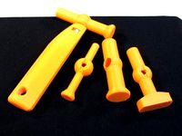
Mallet, Weighted Head by hemocyanin
...handle up a tiny bit to correct that. you'll also probably want to flip the heads over so the wide end is on the buildplate.
thingiverse
free

SSD Adapter for Lenovo TS130 Series by hemocyanin
... the holes don't match up to your specific ssd, i have included the freecad source to make modification of the design easier.
thingiverse
free

Shoe for Hakko FX888D Iron Stand by hemocyanin
...ll enough in that.
i've included the freecad source file to make modifications easier if you want to customize or improve it.
thingiverse
free
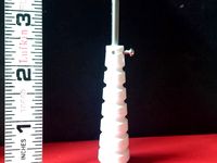
Handle for thread making taps by hemocyanin
... i figure the extra holes are there to be used when i eventually strip a screw hole.
made with freecad -- source file included.
thingiverse
free

Screw Mount Cable Clamps by hemocyanin
...ke them stronger, but these are good enough for my purposes so i'm quitting here.
edit: fixed a small error in 10mm files.
Lulzbot
thingiverse
free
LulzBot Rocktomek by LulzBot
...lulzbot rocktomek by lulzbot
thingiverse
https://download.lulzbot.com/3d_models/rocktomek/
thingiverse
free
THE Lulzbot spool holder
...the lulzbot spool holder
thingiverse
stl and ipt topmount spool holder for lulzbot
thingiverse
free

Lulzbot logo by Halg199703
...lulzbot logo by halg199703
thingiverse
this is the lulzbot logo. i also have a file for dual extruder.
thingiverse
free

LulzBot Bio printer Model
...lulzbot bio printer model
thingiverse
this is a model of the lulzbot bioprinter
thingiverse
free
Lulzbot Taz Enclosure by MrMcGuire
...lulzbot taz enclosure by mrmcguire
thingiverse
parts for an enclosure for lulzbot taz
thingiverse
free

Lulzbot Spool Holder by MAKE
...lulzbot spool holder by make
thingiverse
a spool holder for your lulzbot.
thingiverse
free

Lulzbot mini spool holder by chewie80524
...lulzbot mini spool holder by chewie80524
thingiverse
this part holds the spool on a lulzbot mini. this design came from lulzbot.
thingiverse
free

Lulzbot Claystruder by 102drewt
...r for the lulzbot taz 4. every thing is snap together, and it only requires a threaded rod, a nut to fit it, and a stepper motor.
thingiverse
free

Lulzbot Mini Enclosure brackets by chewie80524
...lulzbot mini enclosure brackets by chewie80524
thingiverse
lulzbot taz/mini enclosure brackets.
thingiverse
free

Lulzbot mini toolbox by nicsna
...t mini using cura scale down to 0.97.
hope you like it and make sure to leave some feedback or suggestions for my next design. :)
Flashlight
3d_export
$5

Flashlight
...flashlight
3dexport
flashlight
3d_ocean
$6
Flashlight
...flashlight
3docean
beam flashlight light
hello! is pleased to present you my new project-flashlight
3d_export
free
Flashlight
...flashlight
3dexport
the most common portable flashlight.
3d_export
$10

flashlight
...flashlight
3dexport
3d model of a flashlight for horror video games or other
3d_export
$15
flashlight
...flashlight
3dexport
low poly model - flashlight, modeling in blender, texturing in substance painter
turbosquid
$2
Flashlight
...squid
royalty free 3d model flashlight for download as blend on turbosquid: 3d models for games, architecture, videos. (1686591)
turbosquid
$1

Flashlight
...squid
royalty free 3d model flashlight for download as blend on turbosquid: 3d models for games, architecture, videos. (1434506)
turbosquid
$10
Flashlights
...ree 3d model flashlights for download as fbx and unitypackage on turbosquid: 3d models for games, architecture, videos. (1286431)
turbosquid
$5

flashlight
...yalty free 3d model flashlight for download as , fbx, and obj on turbosquid: 3d models for games, architecture, videos. (1657266)
turbosquid
free
Flashlight
...
royalty free 3d model flashlight for download as max and obj on turbosquid: 3d models for games, architecture, videos. (1272424)
Usb
3d_ocean
$3
USB Thumbdrive
...usb thumbdrive
3docean
thumbdrive usb usb drive usb stick
this is a swivel type usb thumb drive.
3d_ocean
$5

Usb Stick
...usb stick
3docean
flash stick usb usb memory usb stick
usb stick created using 3ds max 2015 and rendered on mental ray.
3ddd
$1
USB cable
... кабель , провод
высокополигональные модели кабелей usb.
3d_ocean
$5
USB Stick
...usb stick
3docean
32gb computer memory plug plugin protection usb usb stick
an usb stick with built-in plug protection
3d_ocean
$6

USB Stick
...tick
3docean
32 gb flash ram gigabyte memory metal nand plug ram stick usb usb 3 usb stick
usb stick with texture and normal map.
turbosquid
$5

USBS
...bs
turbosquid
royalty free 3d model usbs for download as max on turbosquid: 3d models for games, architecture, videos. (1466594)
3d_export
$5
usb flash
...usb flash
3dexport
usb flash
3d_export
free
usb flash
...usb flash
3dexport
usb flash
3d_export
free
usb flash
...usb flash
3dexport
usb flash driver
3ddd
$1

usb
...usb
3ddd
флешка
флешка
Mini
turbosquid
$10
Mini Mini Luceplan
...
royalty free 3d model mini mini luceplan for download as max on turbosquid: 3d models for games, architecture, videos. (1227359)
3d_ocean
$39
Mini Cooper
...mini cooper
3docean
cabrioler cooper mini
mini cooper cabrioler
3d_export
$30

Mini lathe
...mini lathe
3dexport
mini lathe
3d_export
$5
mini mouse
...mini mouse
3dexport
mini mouse
3d_export
$5
mini house
...mini house
3dexport
mini house
3d_export
free

Mini Mecha
...mini mecha
3dexport
concept of mini mecha
3d_ocean
$20
Mini Gun
...mini gun
3docean
gatling gun gun machine gun mini gun weapon
model of a mini gatling gun.
3ddd
free
Herve mini
... кофейный , herve
http://www.mobiliavenanti.it/ru/products/hervè-mini
3d_export
$5
mini wall
...mini wall
3dexport
mini wall for living room
3d_export
$5

mini bank
...mini bank
3dexport
mini bank 3d model
Led
3d_export
$5
led
...led
3dexport
the led is cut with all the parts.
3ddd
$1
Monacor / PARL56DMX / LED-320RGBW / LED-345RGBW / LED-300RGB
... прожектор
http://www.monacor.dk/
parl56dmx
led-320rgbw
led-345rgbw
led-300rgb
turbosquid
$10
LED
...led
turbosquid
free 3d model led for download as blend on turbosquid: 3d models for games, architecture, videos. (1691856)
3d_export
$5

led lamp
...led lamp
3dexport
led lamp, brightness animation
3ddd
free
leds-c4
...leds-c4
3ddd
leds-c4
современный торшер
3ddd
free
leds-c4
...leds-c4
3ddd
leds-c4
настольный лампа
turbosquid
$19
LED
... available on turbo squid, the world's leading provider of digital 3d models for visualization, films, television, and games.
turbosquid
$12
Led
... available on turbo squid, the world's leading provider of digital 3d models for visualization, films, television, and games.
turbosquid
free

LED
... available on turbo squid, the world's leading provider of digital 3d models for visualization, films, television, and games.
turbosquid
free
LED
... available on turbo squid, the world's leading provider of digital 3d models for visualization, films, television, and games.
Powered
turbosquid
$100
power
...ower
turbosquid
royalty free 3d model power for download as on turbosquid: 3d models for games, architecture, videos. (1421990)
3d_export
$5

Power
...power
3dexport
3d_export
$5
power outlets
...power outlets
3dexport
power outlets
3ddd
$1
lion power
...lion power
3ddd
лев , статуя
lion power gold sculpture
3ddd
$1
Sea Power
...
компас , море , часы
часы с компасом sea power
3ddd
free
Meridiani / Power
...power
3ddd
meridiani , круглый
стол power производитель meridiani, диаметр 120,высота 67
3d_export
$5

Power Surge
...power surge
3dexport
the power surge is a all mesh carnival ride to lower in game part count and lag
turbosquid
$8
Airport Ground Power Unit (AXA Power )
... available on turbo squid, the world's leading provider of digital 3d models for visualization, films, television, and games.
turbosquid
$50

Power Houser
...rbosquid
royalty free 3d model power houser for download as on turbosquid: 3d models for games, architecture, videos. (1333800)
3d_export
$5

power outlet
...power outlet
3dexport
power outlet<br>format file maya 2018, 3d max 2017, obj, fbx
Printer
archibase_planet
free
Printer
...inter
archibase planet
printer laser printer pc equipment
printer n120614 - 3d model (*.gsm+*.3ds) for interior 3d visualization.
archibase_planet
free
Printer
...rchibase planet
laser printer office equipment computer equipment
printer - 3d model (*.gsm+*.3ds) for interior 3d visualization.
turbosquid
$100
Printer
...er
turbosquid
royalty free 3d model printer for download as on turbosquid: 3d models for games, architecture, videos. (1487819)
turbosquid
$3
Printer
...turbosquid
royalty free 3d model printer for download as max on turbosquid: 3d models for games, architecture, videos. (1670230)
turbosquid
$1
printer
...turbosquid
royalty free 3d model printer for download as max on turbosquid: 3d models for games, architecture, videos. (1595546)
turbosquid
$1
printer
...turbosquid
royalty free 3d model printer for download as max on turbosquid: 3d models for games, architecture, videos. (1595105)
turbosquid
$10
Printer
...id
royalty free 3d model printer for download as max and 3dm on turbosquid: 3d models for games, architecture, videos. (1607146)
turbosquid
$7
Printer
...royalty free 3d model printer for download as ma, ma, and obj on turbosquid: 3d models for games, architecture, videos. (1644580)
turbosquid
$30
Printer
... available on turbo squid, the world's leading provider of digital 3d models for visualization, films, television, and games.
turbosquid
$20
Printer
... available on turbo squid, the world's leading provider of digital 3d models for visualization, films, television, and games.
Lighting
archibase_planet
free
Light
...light archibase planet lamp lighting light light - s2 - 3d model for interior...
archibase_planet
free
Light
...light archibase planet light luminaire lighting light l0465 - 3d model (*.gsm+*.3ds) for interior 3d...
3d_export
$5
lighting
...lighting
3dexport
lighting
3d_export
$5

lighting
...lighting
3dexport
lighting in livingroom
turbosquid
$3
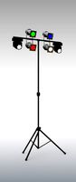
Lighting Tree with Lights
...d model lighting tree with lights for download as max and 3ds on turbosquid: 3d models for games, architecture, videos. (1585507)
archibase_planet
free
Light
...light archibase planet luster lighting solution light - s - 3d model for interior...
archibase_planet
free
Light
...light archibase planet luster lamp lighting light 1 - 3d model for interior 3d...
archibase_planet
free
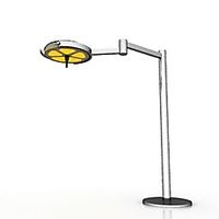
Lights
...lights
archibase planet
surgical lights surgical lamp
surgical lights (floor) - 3d model for interior 3d visualization.
archibase_planet
free
Light
...light archibase planet lighting luminaire candlelight light l0463 - 3d model (*.gsm+*.3ds) for...
3d_export
$18
street light-lighting-light-xia bing
...
3dexport
street light-lighting-light-xia bing<br>max 2015 v-ray 3 max 2015<br>textures<br>all files in zip...
Others
design_connected
$16
ST12 Other
...signconnected
photo-realistic 3d models of the st12 other stool from e15 for 3d architectural and interior design presentations.
turbosquid
$26

Oar and Other
...quid
royalty free 3d model oar and other for download as fbx on turbosquid: 3d models for games, architecture, videos. (1473409)
turbosquid
$5
chair with other
...id
royalty free 3d model chair with other for download as ma on turbosquid: 3d models for games, architecture, videos. (1171468)
3ddd
$1
parfume and other
...parfume and other
3ddd
тумбочка
create by sametyuzer
turbosquid
$79
The Others Collection
...others collection for download as 3ds, max, obj, fbx, and dae on turbosquid: 3d models for games, architecture, videos. (1480228)
turbosquid
$25

Other Man
... available on turbo squid, the world's leading provider of digital 3d models for visualization, films, television, and games.
turbosquid
$15

other car.max
... available on turbo squid, the world's leading provider of digital 3d models for visualization, films, television, and games.
turbosquid
$2
Other Mothers Hand
... 3d model other mothers hand for download as ma, fbx, and obj on turbosquid: 3d models for games, architecture, videos. (1663825)
turbosquid
$8

other sport wheel
... available on turbo squid, the world's leading provider of digital 3d models for visualization, films, television, and games.
turbosquid
$2

pool and other elements
... available on turbo squid, the world's leading provider of digital 3d models for visualization, films, television, and games.
Using
3ddd
$1
US flag
...us flag
3ddd
флаг
us flag
3d_export
free

Among us
...among us
3dexport
among us red
3d_export
free

Among Us
...among us
3dexport
this 3d-model of a character from the game "among us". it can be used as a toy or decoration.
3d_export
$6
among us
...among us
3dexport
doll from among us in red
3d_export
$5
amoung us
...amoung us
3dexport
amoung us character. was created by cinema 4d 19
3d_export
$5
Humvee us
...humvee us
3dexport
humvee us 3d model good quality for animation
3d_export
$15

among us
...among us
3dexport
turbosmooth modifier can be used to increase mesh resolution if necessary
3d_export
$25

mailbox us
...mailbox us
3dexport
low poly model mailbox us. modeling in the blender, texturing in substance painter
design_connected
$13
Use Me
...use me
designconnected
sitland use me computer generated 3d model. designed by paolo scagnellato.
3d_export
$5

Among Us
...rt
the among us model comes in a variety of colors that can be customized by anyone, and even works with little in the animation