Thingiverse
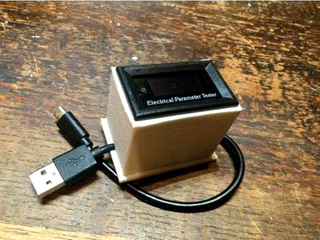
USB electrical parameter tester - volt amp power watt by Fluby
by Thingiverse
Last crawled date: 3 years ago
What's this then?
I wanted to know how much current is being drawn by my Pico when running whatever
Parts
7in1 OLED Electrical Parameter Meter Voltage Current Power Energy Tester about £10
Any USB A to micro cable - but of course you could use any cable that charges things
Little bit of stripboard, and a few bits of thin cable
Solder and soldering iron
What to do
order your parts
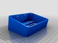
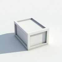
Print the case
Clean it up - the base fit is tight - so might need sanding/scraping. Make the base fit the body first.
Cut your USB cable in half (or whatever proportions you like)
Strip 10mm of sleeving, and expose 2mm of the ends of the 4 wires on each end
Unless you have a strange cable, Red is +, Black is GND and the other two are the signals. You can check with a voltmeter
take a bit of stripboard ()or any other method you like) that will fit in the bottom of the box, and solder + and - to one end for the USB A (that's the power IN) and + and - from the micro usb to the other end (that's power OUT)
Then read the connection guide. You will find it easier to make the wires fit if you shorten the thick ones by about half before you start soldering
You will need to make sure that the +IN and the + OUT are connected together (that's the BLUE connection on the diagram), and the THICK red one to - OUT (or the polarity will be wrong)
The rest, just follow the guide.
Connect the other two USB signal wires back together with some spare bits of wire - mine was green to green, white to white but follow your colours - insulate somehow.
Insulate the thin black wire too.
Fit the tester into the top of the box (not the end with the 2 cutouts!)
turn upside down
stuff in the loose bits, then line up the wires and close the base
Test
Plug the USB A into something that is ON. The tester should show a decent voltage, and the current will be 0.
Plug the micro USB end into your Pico (or indeed anything else!) - then the current will show. If that doesn't work check the polarity of the output with a meter. After that you are on your own!
WARNING on accuracy
This works OK above 3.7 volts. When below that, I've found that the reported current falls below what's being drawn before (otherwise it would be magic!) and the other parameters with it. At or below 3.5V it stops working altogether.So for a normal USB feed it will be fine, but as the battery runs down to these levels it isn't.
On the specs (just read them after making it):
Input voltage: 4-20V
Main measurement parameters: run time, temperature, current, voltage, power, capacity, energy.
Size: 4.8 x 3 x 2cm/1.89 x 1.18 x 0.79inch
Weight:31g
Voltage range:DC0-33.00V,DC0-33.00V,DC00.0-99.9V
Current range:0-3.000A,0-9.99A,0-9.99A
Power range:0-99.00W,0-99.99W -330.0W,0-99.99W -999.9W
Energy range:0-999.99Wh,0-3300.0Wh,0-9999.9Wh
Voltage accuracy:(0.3% +2digits),(0.3% +2digits),±(0.5% +1digit)
Current accuracy:±(0.8% +3digits),±(1% +2digits),±(1% +2digits)
Capacity range:0-99.999Ah
Time range: 0-99h59min
Temperature range: -15~60°
I wanted to know how much current is being drawn by my Pico when running whatever
Parts
7in1 OLED Electrical Parameter Meter Voltage Current Power Energy Tester about £10
Any USB A to micro cable - but of course you could use any cable that charges things
Little bit of stripboard, and a few bits of thin cable
Solder and soldering iron
What to do
order your parts
Print the case
Clean it up - the base fit is tight - so might need sanding/scraping. Make the base fit the body first.
Cut your USB cable in half (or whatever proportions you like)
Strip 10mm of sleeving, and expose 2mm of the ends of the 4 wires on each end
Unless you have a strange cable, Red is +, Black is GND and the other two are the signals. You can check with a voltmeter
take a bit of stripboard ()or any other method you like) that will fit in the bottom of the box, and solder + and - to one end for the USB A (that's the power IN) and + and - from the micro usb to the other end (that's power OUT)
Then read the connection guide. You will find it easier to make the wires fit if you shorten the thick ones by about half before you start soldering
You will need to make sure that the +IN and the + OUT are connected together (that's the BLUE connection on the diagram), and the THICK red one to - OUT (or the polarity will be wrong)
The rest, just follow the guide.
Connect the other two USB signal wires back together with some spare bits of wire - mine was green to green, white to white but follow your colours - insulate somehow.
Insulate the thin black wire too.
Fit the tester into the top of the box (not the end with the 2 cutouts!)
turn upside down
stuff in the loose bits, then line up the wires and close the base
Test
Plug the USB A into something that is ON. The tester should show a decent voltage, and the current will be 0.
Plug the micro USB end into your Pico (or indeed anything else!) - then the current will show. If that doesn't work check the polarity of the output with a meter. After that you are on your own!
WARNING on accuracy
This works OK above 3.7 volts. When below that, I've found that the reported current falls below what's being drawn before (otherwise it would be magic!) and the other parameters with it. At or below 3.5V it stops working altogether.So for a normal USB feed it will be fine, but as the battery runs down to these levels it isn't.
On the specs (just read them after making it):
Input voltage: 4-20V
Main measurement parameters: run time, temperature, current, voltage, power, capacity, energy.
Size: 4.8 x 3 x 2cm/1.89 x 1.18 x 0.79inch
Weight:31g
Voltage range:DC0-33.00V,DC0-33.00V,DC00.0-99.9V
Current range:0-3.000A,0-9.99A,0-9.99A
Power range:0-99.00W,0-99.99W -330.0W,0-99.99W -999.9W
Energy range:0-999.99Wh,0-3300.0Wh,0-9999.9Wh
Voltage accuracy:(0.3% +2digits),(0.3% +2digits),±(0.5% +1digit)
Current accuracy:±(0.8% +3digits),±(1% +2digits),±(1% +2digits)
Capacity range:0-99.999Ah
Time range: 0-99h59min
Temperature range: -15~60°
Similar models
grabcad
free

USB Current Voltage Tester
...testing for usb port output voltage and output current, real-time display
detection range 3~7v / 0~3a
measurement error: +/- 1%
grabcad
free

Drok Buck Power Supply 15A/750W
...tion function: overvoltage, overcurrent, overpower value can be set by user, which will help to protect the module from damaging.
thingiverse
free
Peacefair PZEM-051 Volt/Am meter enclosure by sb43201
...t is 10~9999kwh.
voltage: test range: 6.5~100v
display format: 6.50~99.99v
current: test range: 0~100a
display format: 0.00~99.99
thingiverse
free

JUUL Micro usb charger sleeve by clayshieh
...arry around the juul charger.
all you need are:
smd micro usb type b female socket
a bit of hard bendable wire
a bit of thin wire
thingiverse
free

TEVO Black Widow Control Box Cover with PZEM-051 Wattage Meter by sb43201
...t is 10~9999kwh.
voltage: test range: 6.5~100v
display format: 6.50~99.99v
current: test range: 0~100a
display format: 0.00~99.99
thingiverse
free
Makita Battery USB Power Distribution
...er to make changes. some very simple wiring is required to connect the battery, a power switch, and the power distribution board.
grabcad
free

4 DIGIT Bit 0.36 inch Mini Digital Voltmeter Volt Voltage Meter LED Panel Electric Voltage Tester 3 Wires DC 0-100V 12V DC Voltmeter
...voltmeter volt voltage meter led panel electric voltage tester 3 wires 12v 24v 48v dc 0-100v dc voltmeter for auto car motorcycle
3dwarehouse
free

usb to micro usb cable
...usb to micro usb cable
3dwarehouse
usb to micro usb cable #cable #connector #cord #micro #plug #usb #wire
cg_trader
$2

magnetic cable USB types
...on kindly
voxelize cable charger usb micro usbc iphone android wire power technology connection plug electrical electronics other
cg_trader
$9

Utility Power Pole Electrical Distribution
...ricity technology equipment connection energy cable wire supply connector electrical outlet voltage various models various models
Fluby
thingiverse
free

pico standoff remixed by Fluby
...mixed by fluby
thingiverse
just changed to suit my need, cut out some of the detail to aid cooling, and extended the lugs a bit.
thingiverse
free

filament guide with wheeled bearing by Fluby
...ing by fluby
thingiverse
remix of work of others done here. fits the z axis to bearing here.
608 'roller skate' bearing
thingiverse
free

6 bearing spool holder by Fluby
... to change, and fits any ender with the steel upright. works with the rest of the filament management on here.
use 608 bearings.
thingiverse
free

camera bracket base stronger by Fluby
...m wall for strength.
maybe print horizontal? my original sheared off.
print supports everywhere. it needs them inside the model.
thingiverse
free

fancy z axis knob by Fluby
...uite fine for best effect. (this was printed with a .6 nozzle - bit rubbish)
made small to avoid it hitting my to z axis mounting
thingiverse
free

3mm sheet connectors propogator by Fluby
..., and this stuff joins it or holds while glueing, or locates to the rather unique base.
no idea if anyone will find them helpful
thingiverse
free

z axis top-guide-plus-filament-guide-bracket by Fluby
...r work people have done. fits the filament roller here
remix of this - but stronger - mine broke when printed so i beefed it up
thingiverse
free

extruder knob helix motion indicator by Fluby
...nob that was restricting the height of my models when at the top, hitting my z axis top bracket
best printed at a high resolution
thingiverse
free

BTT filament sensor bracket and filament guide for upgraded metal extruder head by Fluby
...t.
seehttps://www.thingiverse.com/thing:4717518https://www.thingiverse.com/thing:4651070https://www.thingiverse.com/thing:3061551
thingiverse
free

Case for IR-CUT Focusable Camera Module 5MP Webcam Video 1080p For Raspberry Pi by Fluby
...nent file as requested. you might ant to flatten them if you do further edits - my editor couldn't handle that.
use 3mm bolts
Tester
turbosquid
$2

tester
... available on turbo squid, the world's leading provider of digital 3d models for visualization, films, television, and games.
turbosquid
$10

Virus tester
... free 3d model virus tester for download as max, fbx, and obj on turbosquid: 3d models for games, architecture, videos. (1526983)
turbosquid
$24
Hipot Tester
...odel hipot tester for download as skp, 3ds, dae, fbx, and obj on turbosquid: 3d models for games, architecture, videos. (1651595)
turbosquid
$10
Tester Cube
... available on turbo squid, the world's leading provider of digital 3d models for visualization, films, television, and games.
turbosquid
free

BIPED tester
... available on turbo squid, the world's leading provider of digital 3d models for visualization, films, television, and games.
turbosquid
$30
99 Tester SM
...e 3d model 99 tester sm for download as ma, max, obj, and fbx on turbosquid: 3d models for games, architecture, videos. (1258979)
turbosquid
$19

Concrete Compression Tester
... available on turbo squid, the world's leading provider of digital 3d models for visualization, films, television, and games.
turbosquid
$15

AC Electric Tester 2
...ectric tester 2 for download as max, ige, obj, stl, and sldpr on turbosquid: 3d models for games, architecture, videos. (1464810)
turbosquid
$14

Digital Electric Tester Pen
...tric tester pen for download as max, ige, obj, stl, and sldpr on turbosquid: 3d models for games, architecture, videos. (1416100)
3d_export
$15
Probe Screwdriver 3D Model
...screw driver voltage volt electronic equipment tool electric contact tester detector flat head electrician electrical probe screwdriver 3d model...
Volt
turbosquid
$49

LG Volt
... available on turbo squid, the world's leading provider of digital 3d models for visualization, films, television, and games.
turbosquid
$5

LG Volt
... available on turbo squid, the world's leading provider of digital 3d models for visualization, films, television, and games.
3d_ocean
$89

Chevrolet Volt 2011
...com/watch?v=bkrxjnzzuf8 the 3d model was created on real car base. model is created accurately, in real units of measurement, ...
3d_export
$5

9 volts battery
...9 volts battery
3dexport
name:
turbosquid
$25
Volt Steampunk Pistol
...yalty free 3d model volt steampunk pistol for download as 3dm on turbosquid: 3d models for games, architecture, videos. (1485860)
turbosquid
$9

Volt black coin
...id
royalty free 3d model volt black coin for download as max on turbosquid: 3d models for games, architecture, videos. (1634433)
turbosquid
$9

Volt gold coin
...uid
royalty free 3d model volt gold coin for download as max on turbosquid: 3d models for games, architecture, videos. (1634429)
turbosquid
$2
plug 220 volt
...id
royalty free 3d model plug 220 volt for download as blend on turbosquid: 3d models for games, architecture, videos. (1499018)
turbosquid
$20
Volte Gun 2
...royalty free 3d model volte gun 2 for download as max and fbx on turbosquid: 3d models for games, architecture, videos. (1383285)
3d_ocean
$18

Chevrolet Volt rim
...hysically accurate materials. it is separated on parts and they are correctly named. so it is easy to use and modify the model...
Watt
3ddd
$1

Watt & Veke
...watt & veke
3ddd
watt & veke
настольная лампа messina фабрики watt & veke.
3ddd
$1

Watt & veke / Soomkai
...
watt & veke , ротанг
стильная люстра из ротанга soomkai фабрики watt&veke.;
3ddd
free
ROLLE Watt&Veke
...rolle , watt&veke
подвесной светильник rolle watt&veke; из осенней коллекции
turbosquid
$35

We Watt Kiosk
...yalty free 3d model we watt kiosk for download as max and fbx on turbosquid: 3d models for games, architecture, videos. (1461926)
3ddd
$1

Luceplan / OTTO Watt
...условия для любых задач, отдыха или работы. пожалуй, идеальный спутник вашего стола.
дополнительные форматы: max(2010), fbx, 3ds.
3d_export
free
1300 watt subwoofer for cars
...1300 watt subwoofer for cars
3dexport
the model is made to take up space in the house or in the car. power 1300 watts.
3ddd
free
Watt&Veke Spring
...авесной светильник от watt & veke spring, подойдет как для детских, так и для строгих интерьеров, особенно в стилистике лофт.
3d_export
$5

30 watts of power 3D Model
...port
30 watts power 3d model factory electric electrical energy high poly
30 watts of power 3d model karenmodeling 84649 3dexport
3ddd
$1
Watt&Veke Table Lamp
...ble lamp
3ddd
watt&veke
производитель watt&veke;
абажур - vivianne19 h16 ∅19 ∅14
опора для абажура - henning h30 ∅12
3d_export
$5

Substation 110 watts power 3D Model
...odel factory electric electrical energy high poly substation 110
substation 110 watts power 3d model karenmodeling 84650 3dexport
Parameter
turbosquid
$15

06 PARAMETIC PATTERN
...l 06 parametic pattern for download as 3ds, max, obj, and fbx on turbosquid: 3d models for games, architecture, videos. (1435324)
turbosquid
$15

04 PARAMETIC PATTERN
...l 04 parametic pattern for download as 3ds, max, obj, and fbx on turbosquid: 3d models for games, architecture, videos. (1435316)
turbosquid
$15

03 PARAMETIC PATTERN
...l 03 parametic pattern for download as 3ds, max, obj, and fbx on turbosquid: 3d models for games, architecture, videos. (1435314)
turbosquid
$15

01 PARAMETIC PATTERN
...l 01 parametic pattern for download as 3ds, max, obj, and fbx on turbosquid: 3d models for games, architecture, videos. (1435224)
turbosquid
free

Short chair Revit 2012 (with material parameter)
... available on turbo squid, the world's leading provider of digital 3d models for visualization, films, television, and games.
turbosquid
free

Executive chair Revit 2012 (with material parameters)
... available on turbo squid, the world's leading provider of digital 3d models for visualization, films, television, and games.
turbosquid
free

Concrete Truck (Revit 2012 with material parameters)
... available on turbo squid, the world's leading provider of digital 3d models for visualization, films, television, and games.
turbosquid
free

Office Seat in Revit 2012 (with material parameter)
... available on turbo squid, the world's leading provider of digital 3d models for visualization, films, television, and games.
turbosquid
free
Sofa (Revit 2012 with materials and dimensions parameters)
... available on turbo squid, the world's leading provider of digital 3d models for visualization, films, television, and games.
turbosquid
free

Office Desk Revit 2012 (materials and dimenions parameters)
... available on turbo squid, the world's leading provider of digital 3d models for visualization, films, television, and games.
Usb
3d_ocean
$3
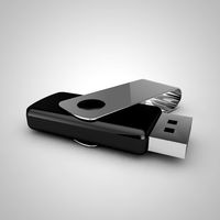
USB Thumbdrive
...usb thumbdrive
3docean
thumbdrive usb usb drive usb stick
this is a swivel type usb thumb drive.
3d_ocean
$5

Usb Stick
...usb stick
3docean
flash stick usb usb memory usb stick
usb stick created using 3ds max 2015 and rendered on mental ray.
3ddd
$1
USB cable
... кабель , провод
высокополигональные модели кабелей usb.
3d_ocean
$5
USB Stick
...usb stick
3docean
32gb computer memory plug plugin protection usb usb stick
an usb stick with built-in plug protection
3d_ocean
$6

USB Stick
...tick
3docean
32 gb flash ram gigabyte memory metal nand plug ram stick usb usb 3 usb stick
usb stick with texture and normal map.
turbosquid
$5

USBS
...bs
turbosquid
royalty free 3d model usbs for download as max on turbosquid: 3d models for games, architecture, videos. (1466594)
3d_export
$5
usb flash
...usb flash
3dexport
usb flash
3d_export
free
usb flash
...usb flash
3dexport
usb flash
3d_export
free

usb flash
...usb flash
3dexport
usb flash driver
3ddd
$1

usb
...usb
3ddd
флешка
флешка
Electrical
3d_export
$5
Electric pole
...electric pole
3dexport
electric pole for street, electricity line
3ddd
$1
electric mixer
...electric mixer
3ddd
electric mixer , миксер
electric mixer
3ddd
$1

electrical installation
...electrical installation
3ddd
electrical installation , розетка
electrical installation
turbosquid
$19
The electric water heater electric
... available on turbo squid, the world's leading provider of digital 3d models for visualization, films, television, and games.
turbosquid
free
Electrical Outlet electric splitter
... available on turbo squid, the world's leading provider of digital 3d models for visualization, films, television, and games.
3d_ocean
$20
Electric Guitar
...electric guitar
3docean
electric electric guitar guitar music music instrument
model of a electric guitar created in maya.
3d_ocean
$12
Electric Shaver
...electric shaver
3docean
electric electric shaver hair removal personal care shaver shaving
electric shaver created in 3ds max.
3ddd
$1
electrical switch
...h
3ddd
electrical , розетка
electrical switch from bticino company
series livinglight
3d_export
$7
Electric Conveyor
...electric conveyor
3dexport
electric conveyor
3d_export
$5
electric drums
...electric drums
3dexport
electric drums
Power
turbosquid
$100
power
...ower
turbosquid
royalty free 3d model power for download as on turbosquid: 3d models for games, architecture, videos. (1421990)
3d_export
$5

Power
...power
3dexport
3d_export
$5
power outlets
...power outlets
3dexport
power outlets
3ddd
$1
lion power
...lion power
3ddd
лев , статуя
lion power gold sculpture
3ddd
$1
Sea Power
...
компас , море , часы
часы с компасом sea power
3ddd
free

Meridiani / Power
...power
3ddd
meridiani , круглый
стол power производитель meridiani, диаметр 120,высота 67
3d_export
$5

Power Surge
...power surge
3dexport
the power surge is a all mesh carnival ride to lower in game part count and lag
turbosquid
$8
Airport Ground Power Unit (AXA Power )
... available on turbo squid, the world's leading provider of digital 3d models for visualization, films, television, and games.
turbosquid
$50

Power Houser
...rbosquid
royalty free 3d model power houser for download as on turbosquid: 3d models for games, architecture, videos. (1333800)
3d_export
$5

power outlet
...power outlet
3dexport
power outlet<br>format file maya 2018, 3d max 2017, obj, fbx
Amp
design_connected
$16
Amp
...amp
designconnected
normann copenhagen amp computer generated 3d model. designed by legald, simon.
3ddd
$1
amp
...amp
3ddd
:-o
3ddd
free
A&X
...a&x
3ddd
a&x
современная кровать фабрики a&x;
3ddd
$1

Molteni & C Night & Day
...molteni & c night & day
3ddd
molteni&c
molteni & c night & day nel248a
3ddd
$1

Molteni & C - Night & Day
...mp;amp; day
3ddd
molteni&c , кушетка
molteni & c - night & day ncl 126/a
3ddd
$1

Villeroy & Boch / Loop & Friends & L'Aura
...op & friends & l'aura
3ddd
villeroy&boch
loop & friends раковина для установки на столешницу
3ddd
free
barovier&toso
...ddd
классическая люстра barovier&toso , barovier&toso
barovier&toso;
3ddd
$1
Стул A&D
...стул a&d
3ddd
a&d
chair a&d;
3ddd
$1

Night&Day
...p;c , night&day
http://www.formul.ru/products/mebel_dlja_spalni/196588
3ddd
$1
B&B
...b&b
3ddd
b&b italia
statue b&b italy