Thingiverse
Ultralight Endfed Triband Half-Wave Antenna by mfhepp
by Thingiverse
Last crawled date: 3 years, 1 month ago
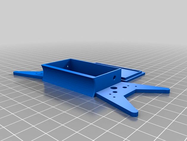
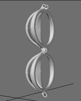
These are all the mechanical parts to build a superlight version of a popular design for a compact tri-band endfed antenna for 40, 20, and 10 m with a loading coil.
The antenna is basically the design described by VK3YY at https://vk3yy.wordpress.com/2014/08/31/end-fed-for-40m20m10m/. The 3D-printed parts allow, however, for a much lighter version with a better handling.
You need to print the following parts:
1 x winder with cover
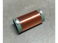
1 x loading coil tube
2 x loading coil tube caps
2 x clips
1 x insulator (or 2 for inverted vee option).
Here is a brief description of the parts:
The winder and cover is for the T82-43 or T50-43 toroid for the impedance transformer. The 3.2 mm holes are meant for RG174 coax and act as a strain relief, too. Be careful not to bend the coax too sharply or it may be damaged and a high SWR could be the result.
The smaller holes in the winder are meant as a strain relief for the main radiator and a ca. 2m counterpoise, which I found helpful.
The loading coil is to be wound on the 45 mm tube with AWG 26 wire (51 turns) or similar. Glue the ends of the wire to the tube with superglue.
Then, feed the antenna wire for the 40m part (ca. 2m) and the main part (ca. 11 m) through the holes in the cap part for the coil.
Finally, mount the caps to the tube with superglue. Since this is irreversible and you cannot re-insert the antenna wire afterwards, make sure they are in place and can't slip out.
Solder the antenna wire to the AWG26 and secure the loose cables with superglue. Afterwards, the whole coil and all holes should be protected with shrink tube and ideally liquid electrical tape, as available from sotabeams.
Feed a ca. 50 - 60 mm rubber band through each of the two clips (hooks). The clips serve two purposes: First, they hold the coil attached to the matching round side of the winder during transport. Second, one of them can and should be used to attach the loading coil to the antenna mast (if it is a lightweight, fishing pole type, as from DX wire or sotabeams). This greatly reduces the stress on the top of the mast. The second one can be used to fix the end of the antenna wire to the mast ca. 1.5 m above the ground and guide it to the ground in a sloped style. This is necessary with masts shorter than 10 m because the overall antenna radiator is ca. 12m long.
The insulator is for the top part of the antenna wire when used as a vertical or sloper. If you want to use it as an inverted vee, you may want to add another one shortly after the loading coil (in the direction to the winder/transformer).
When tuning the antenna, start with the 20m section (with the coil and 40m part already attached) and tune it to minimum SWR on ca. 14100 KHz. When done, tune the 2m part of the wire to ca. 7050 KHz.
It is much easier to adjust the antenna wire length at the winder side, even if this means you will have a solder link in the final wire.
Enjoy, and meet you on the bands!
Addition 2016-12-13:
I added a short version of the loading coil, which is just 35 mm long. If you use 0.40mm wire, this will be sufficient to hold the 51 or 51 windings. If you use thicker wire, use the original 45 mm long version. Keep in mind that the length of the coil influences its inductance, so you will need more windings with thicker wire or if you have space between the windings.
I also added a longer coil for the 80m version described by PD7MAA at http://pa-11019.blogspot.de/2012/04/149-transformer-for-endfed-antennas-35.html.
Note that my coil is designed for 0.40 mm wire and thus requires only 138-147 windings to reach an inductance of 110 uH.
There is also a new winder for the 80m coil in the files. This one has room for the coil in the middle of the winder. In this case, you have to put the components for the matching unit into a small extra enclosure of your choice.
The antenna is basically the design described by VK3YY at https://vk3yy.wordpress.com/2014/08/31/end-fed-for-40m20m10m/. The 3D-printed parts allow, however, for a much lighter version with a better handling.
You need to print the following parts:
1 x winder with cover
1 x loading coil tube
2 x loading coil tube caps
2 x clips
1 x insulator (or 2 for inverted vee option).
Here is a brief description of the parts:
The winder and cover is for the T82-43 or T50-43 toroid for the impedance transformer. The 3.2 mm holes are meant for RG174 coax and act as a strain relief, too. Be careful not to bend the coax too sharply or it may be damaged and a high SWR could be the result.
The smaller holes in the winder are meant as a strain relief for the main radiator and a ca. 2m counterpoise, which I found helpful.
The loading coil is to be wound on the 45 mm tube with AWG 26 wire (51 turns) or similar. Glue the ends of the wire to the tube with superglue.
Then, feed the antenna wire for the 40m part (ca. 2m) and the main part (ca. 11 m) through the holes in the cap part for the coil.
Finally, mount the caps to the tube with superglue. Since this is irreversible and you cannot re-insert the antenna wire afterwards, make sure they are in place and can't slip out.
Solder the antenna wire to the AWG26 and secure the loose cables with superglue. Afterwards, the whole coil and all holes should be protected with shrink tube and ideally liquid electrical tape, as available from sotabeams.
Feed a ca. 50 - 60 mm rubber band through each of the two clips (hooks). The clips serve two purposes: First, they hold the coil attached to the matching round side of the winder during transport. Second, one of them can and should be used to attach the loading coil to the antenna mast (if it is a lightweight, fishing pole type, as from DX wire or sotabeams). This greatly reduces the stress on the top of the mast. The second one can be used to fix the end of the antenna wire to the mast ca. 1.5 m above the ground and guide it to the ground in a sloped style. This is necessary with masts shorter than 10 m because the overall antenna radiator is ca. 12m long.
The insulator is for the top part of the antenna wire when used as a vertical or sloper. If you want to use it as an inverted vee, you may want to add another one shortly after the loading coil (in the direction to the winder/transformer).
When tuning the antenna, start with the 20m section (with the coil and 40m part already attached) and tune it to minimum SWR on ca. 14100 KHz. When done, tune the 2m part of the wire to ca. 7050 KHz.
It is much easier to adjust the antenna wire length at the winder side, even if this means you will have a solder link in the final wire.
Enjoy, and meet you on the bands!
Addition 2016-12-13:
I added a short version of the loading coil, which is just 35 mm long. If you use 0.40mm wire, this will be sufficient to hold the 51 or 51 windings. If you use thicker wire, use the original 45 mm long version. Keep in mind that the length of the coil influences its inductance, so you will need more windings with thicker wire or if you have space between the windings.
I also added a longer coil for the 80m version described by PD7MAA at http://pa-11019.blogspot.de/2012/04/149-transformer-for-endfed-antennas-35.html.
Note that my coil is designed for 0.40 mm wire and thus requires only 138-147 windings to reach an inductance of 110 uH.
There is also a new winder for the 80m coil in the files. This one has room for the coil in the middle of the winder. In this case, you have to put the components for the matching unit into a small extra enclosure of your choice.
Similar models
thingiverse
free

SOTA 3-Band Vertical Antenne with Loading Coil by mfhepp
...6m fiberglass mast from lambdahalbe.de; it may fit other similar masts. you need 2mm gold-plated plugs (normally used for...
thingiverse
free

Superlight SOTA Vertical for 40-30-20m with Loading Coil by mfhepp
...balun" from richard newstead, g3cwi, available via sotabeams (https://www.sotabeams.co.uk/pico-balun-1-1-or-4-1-balun-kit/).
thingiverse
free

Antenna Wire Reel (fits 40m Electric Fence Wire)
...te on. i use petg, since that seems to cope well with rf.
as always i included the freecad file for you to make easy adjustments.
thingiverse
free

Insulating tentioning clip for Antenna Wire (Electric Fence)
... antenna. i use petg since it seems to cope well with rf.
as always i included the freecad file for you to make easy adjustments.
thingiverse
free

Wire Winder by FJAW
...wire winder by fjaw
thingiverse
winder for sota coax / wire (with freecad).
thingiverse
free

Case for simple QRP Endfed Transformer by dhg864
...ded to the holes if required.
the top of the case can be fixed with m3 screws, but you need to drill the thread into the plastic.
thingiverse
free

Air Coil Winder Tool (pitch = double wire diameter) by dhg864
...circuits and antennas.
aircoilwinder-10-d05-p1-80 means:
10mm coil diameter
d05=0.5mm wire diameter
p1=1mm pitch
80mm tool height
thingiverse
free
110uH Loading Coil Form for Short EFHW Antenna by Chetmystery
...terminals and 4mm bolts/hardware. second 4.5mm hole on each end can be used to loop antenna wire through to allow strain relief.
thingiverse
free

2.4 GHz Coax Antenna Stiffener by polysquare
... it as a cutting template to trim the coax core if needed.
fusion360 link to download or review cad files: http://a360.co/2hwyv06
thingiverse
free

Antenna Core by GreyhoundDesign
...inding antenna coils is 8mm and length with space for coils is around 12,2cm.
you need thin painted wire to create coils on core.
Endfed
thingiverse
free
Case for simple QRP Endfed Transformer by dhg864
...ded to the holes if required.
the top of the case can be fixed with m3 screws, but you need to drill the thread into the plastic.
thingiverse
free

40m - 10m multiband EFHW antenna for SOTA
...a step by step building guide on my blog: http://9a5alx.com/40-20-10m-endfedantenna/ ...
thingiverse
free

High-Z End-fed Antenna from Yota 2016 Austria by s00500
...s00500 thingiverse this is the centerpart for the high-z endfed antenna from the workshop at youngsters on the air...
thingiverse
free
Insulating tentioning clip for Antenna Wire (Electric Fence)
...i use it along with my 10m to 80m endfed half wave electric fence antenna. i use petg since...
thingiverse
free

EFHW antenna case and winder for Ham radio by OE5JFE
...ham radio by oe5jfe thingiverse winder and case for endfed half wave antenna for portable radio operation like sota...
Mfhepp
thingiverse
free

Enclosure for the Norcal BLT Tuner (and others) by mfhepp
...nd one for high z vs. low z)
1 5 mm indicator led
2 variable capacitors.
enjoy and hope to meet you on the air!
73s
martin, dk3it
thingiverse
free
Centerpiece for Dipole / Doublet Antennas & Toroid Mount by mfhepp
...pole arms and the rg 174 is done via 1.5 mm and 3 mm holes in the main piece.
enjoy and meet you on the bands!
73s
martin, dk3it
thingiverse
free

Antenna Mast Mount for Elecraft T1 Tuner by mfhepp
...e, you could either use regular rubber bands or apply liquid rubber to the surface of the mount.
enjoy, and see you on the bands!
thingiverse
free
SOTA 3-Band Vertical Antenne with Loading Coil by mfhepp
...design from https://www.thingiverse.com/thing:1173824/ but scaled to 66% in the x and y axis and 100% for the z axis (3 mm high).
thingiverse
free
Superlight SOTA Vertical for 40-30-20m with Loading Coil by mfhepp
...balun" from richard newstead, g3cwi, available via sotabeams (https://www.sotabeams.co.uk/pico-balun-1-1-or-4-1-balun-kit/).
Triband
thingiverse
free

Customizable Triband Flag by daozenciaoyen
...nto triband (three color striped) flags. use the "include shape" selector to create each part separately (1, 2, and 3).
thingiverse
free

uSDX Tri-Band HF Radio Case by scottbaker
...the usdx tri-band radio project can be found here: https://antrak.org.tr/blog/usdx-tribandsdr-all-mode-qrp-transceiver to build this case you will need (in addition...
grabcad
free

Diamond TriBand 2 m VHF, 1.25 m VHF, & 70 cm UHF Amateur Radio / Scanner Antenna
...ge with a sma connector. it has a gain of +4db (2.5x), maximum power capability of 10 watts, and is 13.75" (349.25 mm) long.
grabcad
free

Yaesu VX-7R 2 m VHF, 1.25 m VHF, & 70 cm UHF Amateur Radio / Scanner Antenna
...scanner antenna grabcad this is a stock yaesu vx-7r triband 2 m thru 70 cm amateur radio uhf scanner...
3dwarehouse
free

Triband cocktail table and end table
...triband cocktail table and end table
3dwarehouse
glass and metal cocktail and end table
3dwarehouse
free

T65-24-66A4
...t65-24-66a4 3dwarehouse triband antenna from csa jaybeam #antenna...
3dwarehouse
free

Flag of Barbados
...the island's first independence day. it consists of a triband of two bands of ultramarine separated by a golden...
Ultralight
3d_export
$70

Ultralight 3D Model
...export
ultralight hang glider hangglider air airplane plane wind sailplane sail powered
ultralight 3d model tartino 6235 3dexport
turbosquid
$3

cartoon ultralight
... available on turbo squid, the world's leading provider of digital 3d models for visualization, films, television, and games.
turbosquid
$4

Zephyr 2000 ultralight aircraft Zephyr 2000 ultralight aircraft
... available on turbo squid, the world's leading provider of digital 3d models for visualization, films, television, and games.
turbosquid
$55

Ultralight Helicopter Mozzie Mk III
... helicopter mozzie mk iii for download as blend, obj, and fbx on turbosquid: 3d models for games, architecture, videos. (1532511)
cg_studio
$70
Ultralight3d model
...tralight3d model
cgstudio
.3ds .c4d .obj - ultralight 3d model, royalty free license available, instant download after purchase.
3d_export
$27
SuprGyro 3D Model
...suprgyro 3d model 3dexport micro microlight ultra ultralight gyro gyrocoptor concept new motion aircraft design suprgyro 3d...
3d_export
$60

Paraglider 3D Model
...paraglider 3d model 3dexport paraglider parachute parafoil parasail glider ultralight harness hang gliding flying sail para hangglider paraglider 3d...
3d_export
$58

CriCri 3D Model
...3d 3ds max mesh new aircraft aeroplane smallest twin ultralight microlight lod detail cricri 3d model zarday321 798...
cg_studio
$1900
Jabiru3d model
...jabiru3d model cgstudio aircraft jabiru jabaru ultralite ultralight private small personal general aviation enclosed cockpit composite fibreglass...
3d_export
$80

Ariel Atom 3D Model
...ariel atom 3d model 3dexport ariel atom supercar light ultralight acceleration british sports car top gear alien jay leno...
Wave
3ddd
$1
Wave
...wave
3ddd
wave
wave
3ddd
free

Mobilidea Wave
...mobilidea wave
3ddd
mobilidea , wave
mobilidea wave
design_connected
$22

Wave
...wave
designconnected
royal botania wave computer generated 3d model. designed by nyberg, erik.
3ddd
$1

Elica Wave
... вытяжка , островная
вытяжка подвесная elica wave
3d_export
$5
sideboard wave
...sideboard wave
3dexport
sideboard wave kare design
turbosquid
$5

Waves
... available on turbo squid, the world's leading provider of digital 3d models for visualization, films, television, and games.
turbosquid
$3

Wave
... available on turbo squid, the world's leading provider of digital 3d models for visualization, films, television, and games.
turbosquid
free
Wave
... available on turbo squid, the world's leading provider of digital 3d models for visualization, films, television, and games.
3ddd
$1

Бра PANZERI WAVE
... wave , led , panzeri wave
бра panzeri wave
3ddd
$1

Wave armchair
...
wave , jihye choi
кресло wave armchair от jihye choi. сделано из сталя, дерева и ткани.
Antenna
archibase_planet
free
Antenna
...chibase planet
antenna aerial television antenna
antenna kathrein n090913 - 3d model (*.gsm+*.3ds) for exterior 3d visualization.
archibase_planet
free
Antenna
...antenna
archibase planet
satellite antenna
antenna 1 - 3d model (*.gsm+*.3ds) for exterior 3d visualization.
archibase_planet
free
Antenna
...antenna
archibase planet
equipment satellite antenna
antenna 2 - 3d model (*.gsm+*.3ds) for exterior 3d visualization.
archibase_planet
free
Antenna
...ntenna
archibase planet
satellite antenna equipment dish aerial
antenna 3 - 3d model (*.gsm+*.3ds) for exterior 3d visualization.
archibase_planet
free
Antenna
...antenna
archibase planet
satellite antenna dish dish aerial
antenna 4 - 3d model (*.gsm+*.3ds) for exterior 3d visualization.
archibase_planet
free
Antenna
...e planet
antenna dish dish aerial
antenna c-band satellite s180-g n210612 - 3d model (*.gsm+*.3ds) for exterior 3d visualization.
3d_export
$5

car antenna
...car antenna
3dexport
car antenna, antenna, car gadgets
turbosquid
$1

antenna
...rbosquid
royalty free 3d model antenna for download as blend on turbosquid: 3d models for games, architecture, videos. (1655786)
3d_export
free

Station with antenna
...station with antenna
3dexport
station with antenna
turbosquid
$5

Antenna
...id
royalty free 3d model antenna for download as max and fbx on turbosquid: 3d models for games, architecture, videos. (1381532)
Half
turbosquid
$24

Half and Half creamer
... available on turbo squid, the world's leading provider of digital 3d models for visualization, films, television, and games.
3d_ocean
$4
Half Orange
...half orange
3docean
fruit half half orange orange
half orange
3d_export
$5

half-coupling
...g is a part of the gearbox. it is used to connect gearboxes to shafts. also, the half-coupling connects the motors to the shafts.
turbosquid
$2
Pearl_Mermaid Half
...
royalty free 3d model pearl_mermaid half for download as stl on turbosquid: 3d models for games, architecture, videos. (1386771)
turbosquid
$1

Zombie To The Half
...
royalty free 3d model zombie to the half for download as fbx on turbosquid: 3d models for games, architecture, videos. (1472113)
turbosquid
$1

Half Watermelon
...uid
royalty free 3d model half watermelon for download as ma on turbosquid: 3d models for games, architecture, videos. (1671088)
turbosquid
$40
Half-track
...
royalty free 3d model half-track for download as obj and fbx on turbosquid: 3d models for games, architecture, videos. (1300753)
turbosquid
$5

Half watermelon
...lty free 3d model half watermelon for download as obj and stl on turbosquid: 3d models for games, architecture, videos. (1597323)
turbosquid
$5

Half Cabbage
...oyalty free 3d model half cabbage for download as obj and stl on turbosquid: 3d models for games, architecture, videos. (1597317)
turbosquid
$5

Half Cabbage
...oyalty free 3d model half cabbage for download as obj and stl on turbosquid: 3d models for games, architecture, videos. (1597310)