Thingiverse
TTGO T-Beam LORA with buttons and USB by idleshands
by Thingiverse
Last crawled date: 3 years, 4 months ago
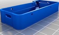
The case by thekwijibo has a few nice features missing from the other models on thingiverse... access to the buttons/USB, a case that allows for "tilted table operation", and it aligned properly with my asymmetrical antenna board.
However, it didn't quite work for my needs, largely because I had a 1-inch screen instead of the 1.3" OLED. This turned out to be something of a blessing, since it also turned out that my preassembled screens weren't mounted squarely, so even if the hole was the correct size, it wouldn't have lined up correctly with my screen.
I ordered my boards (915Mhz) from the "official" aliexpress listing: https://www.aliexpress.com/item/4001220665769.html?spm=a2g0s.9042311.0.0.38664c4dkrE54I
My additions:
1 inch screen insert.stl
This is an insert that snugly fits around the actual screen part of the preassembled 1-inch screen that I received as part of my T-Beam order from aliexpress, since it clips around the screen itself (and not around the circuit board), it allows for a lot of slop in terms of how squarely the assemblers put it together
Since it wraps directly around the screen and "floats" over the opening in the case, it allows some very wide tolerances in screen placement
You may need to play with scaling on this one depending on printer tolerance and/or filament... for one of my filaments it printed so perfectly that it actually "clips on" to the screen, but for another filament it was loose enough that I had to hold it in place while putting it into the case
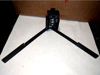
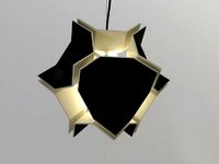
GPS antenna holder.stl
This provides an alternate position for the GPS antenna... stock it's mounted directly beside the LoRa antenna and winds up directly below the case lid... my understanding is that even RF transparent materials can cause reception issues if they are too close (within 3-4mm) to the antenna... so this antenna holder moves the GPS antenna a little further away from the lid, as well as away from the other antenna and a bit further from the circuit board. I'm not an expert by any means, so I'll be testing this to see if it actually improves GPS reception at all, but it made sense to me
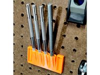
The GPS holder should be added after the PCB is already in the case, if you attempt to add it all at once, it's very difficult to get into the case opening. Once the PCB (and everything below it) is seated as desired, then you can wiggle the GPS holder into place with the arm that runs along the top of the battery holder skewed slightly, so that it will go around the antenna pin, and then slide it back so it's flush against the PCB, and the antenna pin should help hold it in place (see image 3 and notice how the right-most pin is over the top of the "notch" in the GPA antenna holder). There isn't anything permanently attaching the GPS antenna holder and the PCB by default, they sort of just clip/rest together, since there's not a lot of places it can go once the lid is in place .
The screw hole in the GPS antenna holder was originally meant to allow mounting to the PCB, but it turns out the case opening is too small to comfortably allow this, so you should think of it as a visual indicator for orienting the part against the board, rather than as a hole for mounting. If you got creative, you could probably use fishing line or something similar to tie the two together through this hole after assembly.
The GPS antenna holder was designed against my board, and the little notch is supposed to "clip" underneath the nearest pin of the antenna... if the pins of your antenna don't allow for this, you'll likely need to trim that arm back so it doesn't run into the pins, and if the antenna holder winds up moving too much without this, you may want to find an alternative way to secure the antenna holder (hot glue?), or just leave the GPS antenna in the stock position on top of the battery holder. Lots of people use this configuration without issue.
Also note... I saw another case which had a GPS antenna holder, but it mounted the GPS sideways... the metal dot on the GPS antenna is supposed to point a the sky, so make sure however you mount the GPS antenna, it's oriented so that the dot is in the "up" position most of the time when you're using it... it can certainly work in other orientations, but if you want the best performance, point it at the sky.
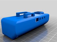
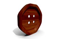
USB Insert - 1.Xmm.stl
This is just a simple insert that goes around the USB plug and covers the surrounding hole to make it look cleaner and possible keep out debris... due to possible differences between boards, it's designed to hook around the board/port, and "float" over the opening in the case
Because of differences in USB cables... you may have problems with certain cables not plugging in all the way with this insert
Designed in 3 different thicknesses (between the "face" of the USB port and the inside of the case), to hopefully account for different USB ports and mounting distances... for my boards, the 1.8mm size was the right fit
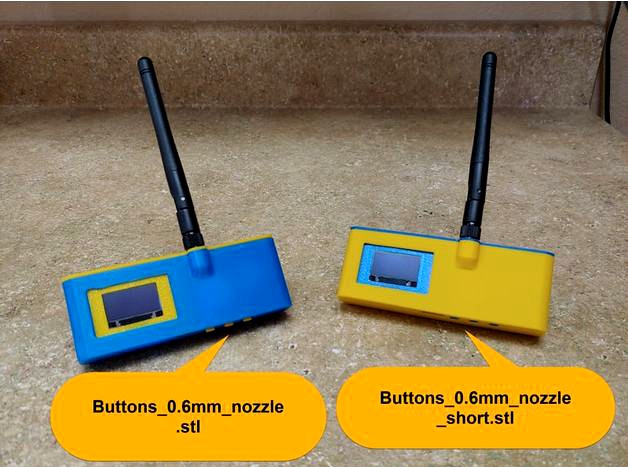
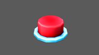
Buttons_0.6mm_nozzle.stl
This is a simple remix of the buttons thekwijibo made, because his design was too fine to work with the 6mm nozzle I have in my printer. This design should also print fine on smaller nozzles
Buttons_0.6mm_nozzle_short.stl
Same as above, but I also shortened the buttons down, so they sit flush with the case. These buttons are much harder to find just by touch (if you have this need, you could remix the buttons with some texture on top to help with this), but they are plenty easy to press even though they are flush with the case.
The original button height makes the buttons easier to press (especially if you're wearing gloves, or trying to operate blindly), but the buttons also stand so proud that you can press them just by setting the radio down on the "bottom" of the case.
The rest of the files included are unchanged from the original design. I beleive "Case.stl" and "096_Body.stl" are largely the same, with just a difference in screen size. For my radios, I printed "Case.stl", since that matched the naming convention of "Lid.stl", all the images you see of my radios in this design are using the "Case.stl" model.
General note, when printing PETG, I've noticed vertical holes seem to "shrink" more than PLA (in this model, it can play a factor in the button and antenna holes, which I have not modified at all from thekwijibo's original model). I suspect this is due to PETG being higher temp and also slightly more elastic than PLA, so when it's printing around a hole, it's basically stretching a molten rubber band around the edge, which winds up pulling itself in further... I believe lowering the temp or slowing the speed might help with this, but I haven't messed with it enough to really say for sure.
However, it didn't quite work for my needs, largely because I had a 1-inch screen instead of the 1.3" OLED. This turned out to be something of a blessing, since it also turned out that my preassembled screens weren't mounted squarely, so even if the hole was the correct size, it wouldn't have lined up correctly with my screen.
I ordered my boards (915Mhz) from the "official" aliexpress listing: https://www.aliexpress.com/item/4001220665769.html?spm=a2g0s.9042311.0.0.38664c4dkrE54I
My additions:
1 inch screen insert.stl
This is an insert that snugly fits around the actual screen part of the preassembled 1-inch screen that I received as part of my T-Beam order from aliexpress, since it clips around the screen itself (and not around the circuit board), it allows for a lot of slop in terms of how squarely the assemblers put it together
Since it wraps directly around the screen and "floats" over the opening in the case, it allows some very wide tolerances in screen placement
You may need to play with scaling on this one depending on printer tolerance and/or filament... for one of my filaments it printed so perfectly that it actually "clips on" to the screen, but for another filament it was loose enough that I had to hold it in place while putting it into the case
GPS antenna holder.stl
This provides an alternate position for the GPS antenna... stock it's mounted directly beside the LoRa antenna and winds up directly below the case lid... my understanding is that even RF transparent materials can cause reception issues if they are too close (within 3-4mm) to the antenna... so this antenna holder moves the GPS antenna a little further away from the lid, as well as away from the other antenna and a bit further from the circuit board. I'm not an expert by any means, so I'll be testing this to see if it actually improves GPS reception at all, but it made sense to me
The GPS holder should be added after the PCB is already in the case, if you attempt to add it all at once, it's very difficult to get into the case opening. Once the PCB (and everything below it) is seated as desired, then you can wiggle the GPS holder into place with the arm that runs along the top of the battery holder skewed slightly, so that it will go around the antenna pin, and then slide it back so it's flush against the PCB, and the antenna pin should help hold it in place (see image 3 and notice how the right-most pin is over the top of the "notch" in the GPA antenna holder). There isn't anything permanently attaching the GPS antenna holder and the PCB by default, they sort of just clip/rest together, since there's not a lot of places it can go once the lid is in place .
The screw hole in the GPS antenna holder was originally meant to allow mounting to the PCB, but it turns out the case opening is too small to comfortably allow this, so you should think of it as a visual indicator for orienting the part against the board, rather than as a hole for mounting. If you got creative, you could probably use fishing line or something similar to tie the two together through this hole after assembly.
The GPS antenna holder was designed against my board, and the little notch is supposed to "clip" underneath the nearest pin of the antenna... if the pins of your antenna don't allow for this, you'll likely need to trim that arm back so it doesn't run into the pins, and if the antenna holder winds up moving too much without this, you may want to find an alternative way to secure the antenna holder (hot glue?), or just leave the GPS antenna in the stock position on top of the battery holder. Lots of people use this configuration without issue.
Also note... I saw another case which had a GPS antenna holder, but it mounted the GPS sideways... the metal dot on the GPS antenna is supposed to point a the sky, so make sure however you mount the GPS antenna, it's oriented so that the dot is in the "up" position most of the time when you're using it... it can certainly work in other orientations, but if you want the best performance, point it at the sky.
USB Insert - 1.Xmm.stl
This is just a simple insert that goes around the USB plug and covers the surrounding hole to make it look cleaner and possible keep out debris... due to possible differences between boards, it's designed to hook around the board/port, and "float" over the opening in the case
Because of differences in USB cables... you may have problems with certain cables not plugging in all the way with this insert
Designed in 3 different thicknesses (between the "face" of the USB port and the inside of the case), to hopefully account for different USB ports and mounting distances... for my boards, the 1.8mm size was the right fit
Buttons_0.6mm_nozzle.stl
This is a simple remix of the buttons thekwijibo made, because his design was too fine to work with the 6mm nozzle I have in my printer. This design should also print fine on smaller nozzles
Buttons_0.6mm_nozzle_short.stl
Same as above, but I also shortened the buttons down, so they sit flush with the case. These buttons are much harder to find just by touch (if you have this need, you could remix the buttons with some texture on top to help with this), but they are plenty easy to press even though they are flush with the case.
The original button height makes the buttons easier to press (especially if you're wearing gloves, or trying to operate blindly), but the buttons also stand so proud that you can press them just by setting the radio down on the "bottom" of the case.
The rest of the files included are unchanged from the original design. I beleive "Case.stl" and "096_Body.stl" are largely the same, with just a difference in screen size. For my radios, I printed "Case.stl", since that matched the naming convention of "Lid.stl", all the images you see of my radios in this design are using the "Case.stl" model.
General note, when printing PETG, I've noticed vertical holes seem to "shrink" more than PLA (in this model, it can play a factor in the button and antenna holes, which I have not modified at all from thekwijibo's original model). I suspect this is due to PETG being higher temp and also slightly more elastic than PLA, so when it's printing around a hole, it's basically stretching a molten rubber band around the edge, which winds up pulling itself in further... I believe lowering the temp or slowing the speed might help with this, but I haven't messed with it enough to really say for sure.
Similar models
thingiverse
free

STM32F411 Black pill simple 3D model by eljotto
...ements are not as interesting, and are way smaller to cause issues when designing 3d prints around this board, so i skipped them.
thingiverse
free

Sino:bit case by larryl719
... devices at the moment, i put tie wraps through the pairs of holes on either side by the buttons to hold the board into the case.
thingiverse
free

NCE BD20 mount
...9;ve uploaded a fusion 360 archive file so you can change the "board" parameters to match any mountless board you have.
thingiverse
free

Sdrive Max 2.4" Case
...ow for the smaller screen. you will need to desolder the button which is on the top of the board so the case can close properly.
thingiverse
free

Snap Panel Mount for Micro-USB Breakout by Sp4rkai
...reakout board.
fits an 11/16th" (11.2mm) hole, built around an asafruit board, but will fit any 1/8" (3.2mm) pcb board.
thingiverse
free
X8R case by mlinuxguy
...rs at the end to help "clip" in the antenna's. the locking tab is also a tiny bit taller to help lock in the x8r.
thingiverse
free

Case for 4 Smoother Diode Boards (JeffCo) by Jeff5263
...i don't have any specific place in mind to mount it. if nothing else you can use one bracket to keep it from rattling around.
thingiverse
free

PCB case VL4.1 by TheMatt2582
...se
i made a case to protect my pcb. i made holes in the bottom so you can secure your pcb and bridges so it's easy to print.
thingiverse
free
Razor Knives (8mm) Pegboard Holder by danda398476
.... i've added an extended pin but be warned i haven't tested it yet. if you beat me to it, please let me know how it went.
thingiverse
free

Mikromedia Board Case by giufini
...oom to also host an extension board, so enabling user to place components and provide additional functionality to the base board.
Idleshands
thingiverse
free

Ear Wall Hooks by idleshands
...e of filament colors for these :)
printed mine at .15mm layer height and they came out looking pretty great, no supported needed.
thingiverse
free

Versaflo mask to CPAP hose adapter by idleshands
...ask and lock it into place). this also means you might have to play with scaling to adjust for differences in printer tolerances.
Ttgo
thingiverse
free
Case ESP32 TTGO by binaryfpv
...case esp32 ttgo by binaryfpv
thingiverse
case esp32 ttgo
thingiverse
free

TTGO TM ESP32 case
...ttgo tm esp32 case
thingiverse
new case for ttgo tm
thingiverse
free

TTGO T5 Case by Niklas_Voigt
...ttgo t5 case by niklas_voigt
thingiverse
simple case for wallmount the ttgo t5.
thingiverse
free

TTGO T5 v2.2 case
...ttgo t5 v2.2 case
thingiverse
simple case for ttgo t5 v2.2
thingiverse
free

TTGO with Battery by sash482
...ttgo with battery by sash482
thingiverse
remix for pla
thingiverse
free

TTGO LoRa Case by sqij
...ttgo lora case by sqij
thingiverse
a case for the ttgo lora32 v2 board: https://it.aliexpress.com/item/4000632993971.html
thingiverse
free

TTGO Lora32 Esp32 Oled_case
...ttgo lora32 esp32 oled_case
thingiverse
caja para meter la pcb ttgo lora32 esp32 con pantalla oled
thingiverse
free

TTGO Decoder T-Beam V07
...ttgo decoder t-beam v07
thingiverse
ttgo -t (v07) beam decoder with oled
thingiverse
free
TTGO LoRa ESP32 case by ED8617
...ttgo lora esp32 case by ed8617
thingiverse
case for ttgo lora esp32 module with external antenna.
thingiverse
free

TTGO ESP32 OLED 18650 module
...ttgo esp32 oled 18650 module
thingiverse
3d model of ttgo module with esp32, 18650 battery and oled screen
Lora
3ddd
$1
Lora
...lora
3ddd
lora
детская мебель фабрики lora, spain.три цветовых решения в трех файлах.в превью только часть.
turbosquid
$25

lora character
...d
royalty free 3d model lora character for download as blend on turbosquid: 3d models for games, architecture, videos. (1484892)
3d_export
$5
Armchair LORA 3D Model
...armchair lora 3d model
3dexport
armchair lora
armchair lora 3d model yakoff 72258 3dexport
turbosquid
$31

Lora Missile
... available on turbo squid, the world's leading provider of digital 3d models for visualization, films, television, and games.
turbosquid
$15
Lora Stone
... available on turbo squid, the world's leading provider of digital 3d models for visualization, films, television, and games.
turbosquid
$100
Lora Missile Launcher
... available on turbo squid, the world's leading provider of digital 3d models for visualization, films, television, and games.
turbosquid
$16

Lorae Swivel Chair
... available on turbo squid, the world's leading provider of digital 3d models for visualization, films, television, and games.
3d_export
$80
Cafe Lora 3D Model
...model
3dexport
dining room hall scene chair table ditaliiled cafe restaurant interior
cafe lora 3d model lipenko95 93262 3dexport
turbosquid
$49
Ursula and Lora Table Set
...model ursula and lora table set for download as obj and blend on turbosquid: 3d models for games, architecture, videos. (1155806)
turbosquid
$9

Nightstand, sideboard Lora by Evmoda
...deboard lora by evmoda for download as max, max, max, and obj on turbosquid: 3d models for games, architecture, videos. (1645025)
Beam
archibase_planet
free
Beam
...beam
archibase planet
beam camber-beam hammer-beam
balance beam 2 - 3d model for interior 3d visualization.
design_connected
$16
Beam
...beam
designconnected
van rossum beam computer generated 3d model. designed by rossum, van.
design_connected
$11
Beam
...beam
designconnected
mdf italia beam computer generated 3d model. designed by arrivillaga, luis alberto.
turbosquid
$25

beam
...am
turbosquid
royalty free 3d model beam for download as stl on turbosquid: 3d models for games, architecture, videos. (1674400)
turbosquid
free

beam
... available on turbo squid, the world's leading provider of digital 3d models for visualization, films, television, and games.
3ddd
$1
ZERO, BEAM
...zero, beam
3ddd
zero
поворотная люстра zero , beam
archive3d
free

Beam 3D Model
...archive3d
beam camber-beam hammer-beam
balance beam 2 - 3d model for interior 3d visualization.
3ddd
free
Studio Beam
... navy
светильники studio beam
модели: mariner, ocean mariner, navy.
могут быть в разных цветах
3ddd
$1
Studio Beam
...grupius
производитель studio beam
модели: edison’s rocket pendant, edison’s rocket table lamp,romanov,elena pendant,grupius 1919.
design_connected
$11
I-Beam
...i-beam
designconnected
glas italia i-beam computer generated 3d model. designed by massaud, jean-marie.
Usb
3d_ocean
$3
USB Thumbdrive
...usb thumbdrive
3docean
thumbdrive usb usb drive usb stick
this is a swivel type usb thumb drive.
3d_ocean
$5

Usb Stick
...usb stick
3docean
flash stick usb usb memory usb stick
usb stick created using 3ds max 2015 and rendered on mental ray.
3ddd
$1
USB cable
... кабель , провод
высокополигональные модели кабелей usb.
3d_ocean
$5
USB Stick
...usb stick
3docean
32gb computer memory plug plugin protection usb usb stick
an usb stick with built-in plug protection
3d_ocean
$6

USB Stick
...tick
3docean
32 gb flash ram gigabyte memory metal nand plug ram stick usb usb 3 usb stick
usb stick with texture and normal map.
turbosquid
$5

USBS
...bs
turbosquid
royalty free 3d model usbs for download as max on turbosquid: 3d models for games, architecture, videos. (1466594)
3d_export
$5
usb flash
...usb flash
3dexport
usb flash
3d_export
free
usb flash
...usb flash
3dexport
usb flash
3d_export
free
usb flash
...usb flash
3dexport
usb flash driver
3ddd
$1

usb
...usb
3ddd
флешка
флешка
Buttons
archibase_planet
free
Buttons
...buttons
archibase planet
lift elevator call buttons
elevator call buttons - 3d model for interior 3d visualization.
3ddd
$1
Button
... button , john reeves
набор мебели button от дизайнера john reeves
3d_export
$5
Button
...button
3dexport
smd button<br>verts 2.180<br>faces 3.848
turbosquid
$4

Button
...
turbosquid
royalty free 3d model button for download as fbx on turbosquid: 3d models for games, architecture, videos. (1297941)
turbosquid
$1

Button
...
turbosquid
royalty free 3d model button for download as fbx on turbosquid: 3d models for games, architecture, videos. (1392935)
turbosquid
$9
buttons
...id
royalty free 3d model buttons for download as max and fbx on turbosquid: 3d models for games, architecture, videos. (1404875)
turbosquid
$6

button
...uid
royalty free 3d model button for download as 3dm and max on turbosquid: 3d models for games, architecture, videos. (1669204)
turbosquid
$5
Button
...uid
royalty free 3d model button for download as max and fbx on turbosquid: 3d models for games, architecture, videos. (1710868)
turbosquid
$3

Button
...quid
royalty free 3d model button for download as ma and obj on turbosquid: 3d models for games, architecture, videos. (1510524)
turbosquid
$3
Button
...quid
royalty free 3d model button for download as ma and obj on turbosquid: 3d models for games, architecture, videos. (1509961)
T
design_connected
$11
T & T
...t & t
designconnected
dark t & t computer generated 3d model. designed by de ryck, christophe.
3d_export
$5

t-800
...t-800
3dexport
t-800
3ddd
$1
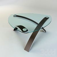
Table T
...table t
3ddd
журнальный
table t
3ddd
free
T-Rex
...t-rex
3ddd
t-rex
rrrrrr
3d_export
$5
t-virus
...t-virus
3dexport
it's t-virus
3d_export
$5

T-26T
...t-26t
3dexport
artillery tractor on the t-26 chassis ussr
3ddd
$1
T 45
...t 45
3ddd
t-45
кабинет руководителя t 45
12 предметов
подробнее:http://www.prezident-mebel.ru/index.php?productid=1541
3ddd
free

SAFE T
...safe t
3ddd
огнетушитель
креативные огнетушители от компании safe t
3d_export
free
t-rex
...t-rex
3dexport
t-rex have normal map and base color textures
3d_export
$75
T-55
...nally, but these improvements made the tank more efficient and lethal. the t-55 was officially adopted by the soviet army in 1958