Thingiverse
Tracked Inspection Bot (TPU) by CammServices
by Thingiverse
Last crawled date: 3 years, 1 month ago
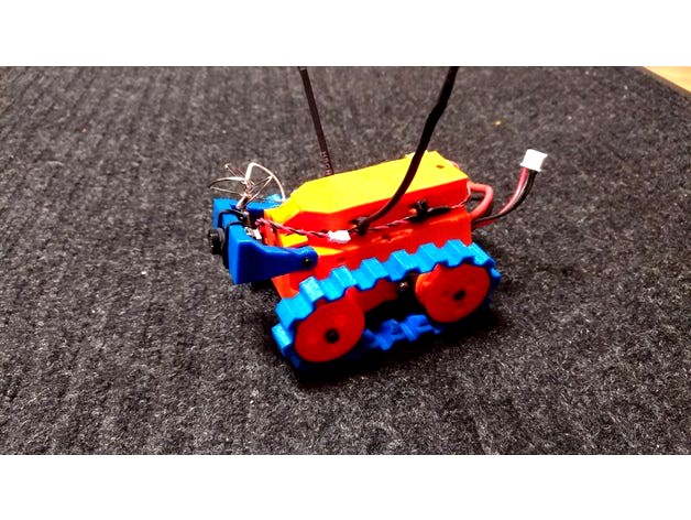
Great Micro Go anywhere tank with tilting FPV camera. I will be adding more options as time goes on, but I wanted to get these files live so people can start printing. I will be posting a build video shortly. This is a TPU/TPE (Semi Flex) print material only design. Turn Off Support material for all parts, you shouldn't need it.
When you finish printing the track give them a bit of stretching to soften them up a bit. They should fit with a bit of slack above the wheels. The Drive wheels are cogged and will move the tracks along just fine.
Battery Bay Dimensions Are:
32mm Wide
10mm Tall
65mm Long
The design will flex to accommodate if sections of the battery are larger. One of the reasons I chose TPU for the material.
Parts List
2x HexTronik MG14 Digital Metal Gear Servos (Modding Information Available Below)
1x Turnigy D56LV Digital Metal Gear Servo
1x Eachine TX03 3-in-1 FPV Camera
1x 3amp Micro UBEC
2 Cell Battery Pack (Recommend: Tattu 650mah for easy 4 hours of drive time.)
A Receiver (Recommend X6R, S6R, X4R or smaller.) X6R and S6R allow for Voltage Telemetry
2x 20mm M3 Screws (Front Riding Wheels)
2x 18mm M3 Screws (From Battery Compartment down to the bottom middle) (Button Cap Recommended)
1x 8mm M3 Screw (Rear) (Button Cap Recommended)
1x 12mm M3 Screw (Front Side Opposite of Servo Output)
1x 14mm M3 Screw (Front Center to RX Bay)
2x 3m Lock Nuts (Inside Lower Body Ride Wheel Axles)
7x 3m Nuts
1x 5mm M2 Screw (Front Servo Camera Mount)
All screws with the exception of the 20mm screws, should be a lower profile button cap design.
Modding the MG14 Servo for continuous Rotation:
-Remove the 4 screws and lift off the bottom housing
-Slide some extra servo wire though to make things easier.
-pushing firmly on the bottom of the motor, release the gear train section from the metal case. Be careful to not separate the gear train section. You will now see the square cased potentiometer next to the motor. Release it from the drive axle. It will be secured with a little bit of adhesive.
-Once the potentiometer is free connect the servo to a servo center tool or a paired receiver with a channel outputting 1500u. Now rotate the center of the potentiometer until the servo stops rotating. It may be a little difficult to find center. If you are not exact after the mod, don't worry you can trim it out with the radio.
-Now Glue the potentiometer so it can't rotate and fold the pins against the potentiometer and cover with a thin bit of shrink wrap.
-Now carefully fit everything back inside of the servo casing with the servo lead exiting out the opposite side of the servo output shaft. The bottom cap may have a small circular spacer depending on the generation. You can remove that piece with a set of needle nose pliers to give yourself more room. Everything should fit back inside the housing.
I would also like to thank the Facebook Group (Tiny Trak - Micro FPV Crawler) Community. It's how I got hooked on these little Crawlers. Their comments and support have been of great help.
https://www.youtube.com/watch?v=YRERZqmnnxM
Similar models
thingiverse
free
Mazebot by chickenchuck
...)
m3 nuts (2x)
for more information about me and my other projects, check out my website at http://netzero.solarlogic.net/andrew/
thingiverse
free

HG P407 forward mounted electronics tray
...2 3mm holes in the battery tray 37.5mm apart.
use 3mm drill bit to clean printed part screw holes.
screw part on to battery tray.
thingiverse
free

Autonomous toy car and FPV car by Inventoteca
...13 bolts m3 (various lengths) 4 screw m2x10 (or similar 4 screw to mount servos 18 bamboo sticks ⌀3...
thingiverse
free

Battery Mount
...ra, it just needed a mount. now it has one.
to assemble, you will need 1x m4x30 screw, 1x m4 nut, 2x m3x10 screws and 2x m3 nuts.
3dwarehouse
free

GRASS Drawer Vionaro H185, Inset accessory set
...device (2x) and special screws (4x) recommended accessoires grass drawer vionaro grass vionaro inset panel, for inset drawer h185
thingiverse
free

PrintBot Droide by DroideComunidad
...ller bqzum
2x continuos rotation servo
1x micro servo (for ultrasonic module or claws)
2x ir module sensor
1x battery compartment
thingiverse
free

Kame: quadruped robot (version with cheap servo)
...on on the board with a multimeter)
trim - d0 (io-16 on esp-12e wifi module, check the connection on the board with a multimeter)
3dwarehouse
free

GRASS Drawer Vionaro H89, Inset accessory set
... device (2x) and special screws (4x) recommended accessoires grass drawer vionaro grass vionaro inset panel, for inset drawer h89
thingiverse
free

Rubber Gun for FPV-Rover by markus_p
...tp://bit.ly/2hy1mvc
2x m5 nuts
1x m5 threaded bar (10cm-15cm)
2x 6mm metal pipe (10cm-15cm)
1x 6mm metal pipe with 5mm hole (5cm)
thingiverse
free

Micro Servo Claw by FelixFoundSheep
... receiver
1x remote control
1x 5-6v battery pack
7x m3 bolts (12-16mm length)
7x m3 nuts
7x locking washers (optional)
7x washers
Cammservices
thingiverse
free

14mm Beeper Holder (Zip Tie) by CammServices
...14mm beeper holder (zip tie) by cammservices
thingiverse
zip tie mount for 14mm beeper
thingiverse
free

Hercules 500mm QuadCopter Dome by CammServices
...es
thingiverse
some of the parts i designed and used on my hobbyking hercules 500mm quad
recommend using tpe/tpu like filaments.
thingiverse
free

Martian II (Battery Holder and Frame Guards) by CammServices
...artian ii (battery holder and frame guards) by cammservices
thingiverse
extras for the martian ii frame
print in tpu or similar.
thingiverse
free

Tough Ducted Micro ABS by CammServices
...ame
for use with:
8.5mm diameter motors
600mah 1 cell
fx798t or similar camera / eachine ef-01 camera
abs is strongly recommended
thingiverse
free

Eachine QX90 (Plus Parts) by CammServices
... or just print rear wire part for all 4 arms.
i designed this for a friend and had to build one of my own.
15 degree camera tilt,
thingiverse
free

RunCam 2 Holder/Guard 15 Degree by CammServices
...ree by cammservices
thingiverse
designed to strap a runcam 2 to the top of a 30mm wide battery using existing strap.
use tpu/tpe
thingiverse
free

Detroit Multirotor Pixel, BeastMode and Whippet Parts by CammServices
...for the detroit multirotor pixel, beastmode and whippet.
for the camera mount: be sure to mirror the print for the opposite side.
thingiverse
free

XT60 LiPo Cap (TPU) by CammServices
...ck i just toss the cap in the box until i charge up a pack again. you can also print in various colours to signify battery state.
thingiverse
free

6x Pi 4 Cluster Case by CammServices
... easy assembly. designed to be used with a 60 mm fan. there are screw holes to mount pi available, but they aren't necessary.
thingiverse
free

Diatone Beta110 H4 V2.0 110 110mm (Plus Parts) by CammServices
...e
upgraded motor mounts and camera mount for the diatone beta110 h4 v2.0 110 110mm
requires an fx806tc fpv camera
print with tpu
Inspection
turbosquid
$15

factory inspection table_01
...free 3d model factory inspection table_01 for download as upk on turbosquid: 3d models for games, architecture, videos. (1505447)
3d_export
$7

carton packaging inspection line robot inspection
...ton packaging is intact equipment, roller conveyor line transportation, pneumatic positioning, like welcome to download learning.
3d_export
$15
Road Inspection Service 3D Model
...sian police road inspection service lowpoly low-poly low poly max fbx dae
road inspection service 3d model cyber3d 86128 3dexport
turbosquid
$149

Inspection and Measuring Tools, Collection
... available on turbo squid, the world's leading provider of digital 3d models for visualization, films, television, and games.
3d_export
$16
glass inspection equipment
...ison of pictures by taking photos, the quality of glass is distinguished, and the last process of glass production is controlled.
3d_export
$150
auto pcb board loder inspection machine
...auto pcb board loder inspection machine
3dexport
auto pcb board loder & inspection machine --> only step file
3d_export
$5
computer vision project part inspection
...computer vision project part inspection
3dexport
3d_export
$22
a filter assembly and inspection line
... by solidworks, proe, ug and other three-dimensional software. the details are detailed. welcome to download.<br>报错 笔记 双语对照
3d_export
$10

mobile phone terminal punching ccd visual inspection packaging equipment
...packaging equipment
3dexport
mobile phone terminal punching, ccd visual inspection and packaging integrated automation equipment
3d_export
$10

Japanese firm inspect
...try. this model can be applied to animated films, short films, virtual environments, augmented environments, 3-d games, and more.
Bot
turbosquid
$19

Bot
... available on turbo squid, the world's leading provider of digital 3d models for visualization, films, television, and games.
turbosquid
free

Bot
... available on turbo squid, the world's leading provider of digital 3d models for visualization, films, television, and games.
3d_export
$10

scanner bot
...scanner bot
3dexport
cool scanner bot who scans for fixing things...
3d_ocean
$9

Apc Bot
...n bot games toys
an all-purpose-constructo-bot. for cartoon purposes. the model is not rigged. please use vray adv for rendering.
3d_export
$75

Bot 3D Model
...bot 3d model
3dexport
robot bot man kiborg character
bot 3d model evgen 19504 3dexport
turbosquid
free

Eye Bot
...eye bot
turbosquid
free 3d model eye bot for download as fbx on turbosquid: 3d models for games, architecture, videos. (1514059)
turbosquid
$29

Gorill-bot
...bosquid
royalty free 3d model gorill-bot for download as fbx on turbosquid: 3d models for games, architecture, videos. (1239456)
turbosquid
$25

Lamp Bot
...bosquid
royalty free 3d model lamp bot for download as blend on turbosquid: 3d models for games, architecture, videos. (1230121)
turbosquid
$10

Spectre Bot
...osquid
royalty free 3d model spectre bot for download as fbx on turbosquid: 3d models for games, architecture, videos. (1616378)
turbosquid
$8

Ultra Bot
...urbosquid
royalty free 3d model ultra bot for download as ma on turbosquid: 3d models for games, architecture, videos. (1330752)
Tpu
3d_export
$7

GEARBOX BUSHING PEUGEOT 307
...gearbox bushing peugeot 307 3dexport print material - elastan\tpu nozzle temperature - 230°с bed temperature - 100°с layer...
3d_export
$5

iphone 11 pro case
...or 6 filling: fill density: 15% pattern: grid material: tpu printing temperature: 238ºc printing plate temperature: 40 or 50ºc...
thingiverse
free

Chair TPU
...chair tpu
thingiverse
... tpu ...
thingiverse
free
Wasserauslauf TPU
...wasserauslauf tpu
thingiverse
wasserauslauf tpu
thingiverse
free
TPU-Coaster by 873chi
...oaster by 873chi
thingiverse
material = tpu
i made a separate type coaster.
since it is tpu, it has elasticity and is practical.
thingiverse
free

Laser HD TPU
...laser hd tpu
thingiverse
transtec laser hd tpu
thingiverse
free
TPU-Cube
...tpu-cube
thingiverse
foldable cube
thingiverse
free

Trampa Wand TPU
...trampa wand tpu
thingiverse
tpu cover, print base down with supports
thingiverse
free
athorbot extrudeur tpu
...athorbot extrudeur tpu
thingiverse
athorbot brother modif pour tpu ou flex
thingiverse
free

Nerf Dart TPU
...nerf dart tpu
thingiverse
nerf dart to be printed in tpu or other flexibles.
size 72x12mm
Tracked
design_connected
$11

Tracks
...tracks
designconnected
bonaldo tracks computer generated 3d model. designed by gilles, alain.
3d_export
$30

TRACK
...track
3dexport
turbosquid
$20

tracks
... available on turbo squid, the world's leading provider of digital 3d models for visualization, films, television, and games.
turbosquid
$5

Tracks
... available on turbo squid, the world's leading provider of digital 3d models for visualization, films, television, and games.
turbosquid
$5

Track
... available on turbo squid, the world's leading provider of digital 3d models for visualization, films, television, and games.
turbosquid
$2

Track
... available on turbo squid, the world's leading provider of digital 3d models for visualization, films, television, and games.
3d_export
$65

track
...track
3dexport
simple rendering of the scene file
3d_export
$65

track
...track
3dexport
simple rendering of the scene file
3d_export
$65

track
...track
3dexport
simple rendering of the scene file
3ddd
free

Стол Bonaldo Tracks
...onaldo , tracks , обеденный
стол bonaldo tracks