Thingiverse
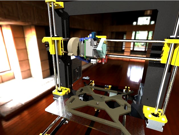
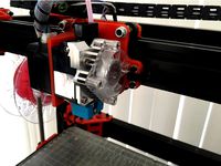
Titan Aero Upgrade for Original Prusa i3 MK2(s) by jltx
by Thingiverse
Last crawled date: 3 years ago
Why do you want this Titan Aero upgrade for your Prusa i3 MK2?
Benefits:
Lighter, more compact assembly with center of mass closer to axis -> higher print speeds, more immune to knocks
see video: http://e3d-online.com/Titan-Aero-Standard-175-12V
440 cc more build volume due to shorter stack
Full X and Y range with additional Z height
Shorter filament path means less ooze and better handles flexible filaments
Easier manual loading and unloading of filament
Simpler nozzle changes with no disassembly
Better print visibility for progress or identify issues
Manual tension adjust, cleaning, maintenance without tools/disassembly
Enhanced part cooling
Minimal changes to stock:
NO FIRMWARE CHANGES
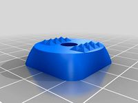
These 4 printed parts + 4 screws + Titan Aero + Motor^
^ This is designed to use a short body nema 17, not the stock unit.
Motor body length must be <= 23mm , such as: https://www.amazon.com/gp/product/B00PNEQ79Q/
If you want to use a motor with 24-26mm body, such as http://e3d-online.com/Electrical/Stepper-Motors/NEMA17-Titan-Slimline, you lose 3mm of X range. See notes at end of build section. You may need to adjust currents as well (see end).
Print (slic3r PE instructions):
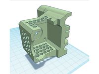
I recommend printing x carriage, aero, pinda mount together
Print in ASA or ABS. PETG can work. Because I am taking advantage of the shorter Titan stack to improve Z, the heater block is closer to the x carriage, so I recommend the e3d silicone sock. The glass transition is roughly: ABS/ASA 100C, PETG 80C, PLA 60C.
aero mount -> object settings: infill 80% or 100% for strength (other two can be normal infill I suspect)
add supports -> use on build plate only which should add very little support
also add brim, maybe 8mm, to help corners hold with ABS/ASA
I printed these in ABS and they came out pretty well. First clean your bed with alcohol and then acetone. I used a 0.4 nozzle, 0.2mm layer, 20% infill, 255C nozzle and 105C bed, no fan. I also put a large plastic tub over the printer as a cheap enclosure to trap heat. I had to clean up the pinda mount slot and aero mount center pin with a knife. Otherwise everything fit nicely.
Blower mount can be printed in PLA, with supports.
I have had good luck with these support settings on PLA
contact Z: 0.15
pattern angle: 20
interface spacing: 0.5
XY: 70%
Build (assumes you are upgrading from stock):
Please read through first to know the order of steps and take your time.
Unwire the extruder wire bundle from the RAMBO. Remove two screws on X motor to loosen and remove belt. Cut the zip ties on x-carriage. Remove stock extruder + x carriage.
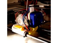
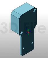
Fit pins of aero mount into holes in X-carriage and screw two ends down with 2 M3x20 (or longer) and washers and nuts, very snug. Screw head fits in recess on back, nut and washer in front. Make sure base of mount is flush against carriage all the way across.
X-carriage mounts like stock onto the X-axis rods (see steps X.8 - X.11 in manual) with zip-tie to linear bearings. Make sure upper left bearing (nearest X motor) is all the way to the outside against the lip of the X-carriage so it most clearance for filament gear.
Insert Nema-17 short body on left side of aero mount with wires toward back and route through wire channel. If your motor has a plug connector, you will need to orient to the front and run wires around to the back. There are zip-tie channels on bottom edge of aero mount to help.
Mount titan on right following instructions at https://wiki.e3d-online.com/wiki/Titan_Aero#Assembly_Steps. You will use no spacer and the short set of screws. Don’t mount heatsink fan yet.
Install cartridges in heater block opposite of what is shown on e3d, so wires exit other direction.
Make sure screws are snug and check clearance of filament gear in slot and between linear bearings on back of X-carriage.
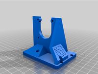
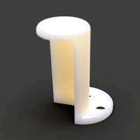
Insert PINDA into pinda mount and add two screws and nuts loosely for now.
Screw pinda mount onto X-carriage, lining up arrows, using M3x25, nut optional. Rotate PINDA body so wire is toward back (it is not centered) to get best clearance to heatsink. Route wire through channel on X-carriage.
Mount heatsink fan onto heatsink according to e3d instructions and route wires next to PINDA wire in channel.
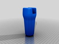
Mount blower fan into blower mount by tipping outlet into mount and rotate to snap in top. Screw with M3x25, head in recess, nut on left.
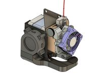
Attach blower mount using ends of the two M3x20 screws holding the aero mount, outside of the existing nuts. There should be room for second nut. See renderings for reference.
Route blower wires alongside the motor wires in channel.
Angle the heater block so the nozzle is nearest the blower outlet and clamp screw is nearest the PINDA. Both the heater and thermistor wires should point right back through the bottom wire channel. Optional: tape piece of aluminum foil to X carriage in recess behind heater and through bottom wire channel to deflect heat, especially if using PETG.
Add e3d silicone sock over heater block.
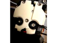
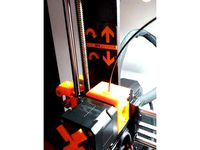
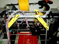
Slide X carriage to extreme left and right and make sure end-stop clicks and no other obstructions. NOTE: if you have MK2S, you may need to Dremel off a bit of the X motor end support if the corner of the motor hits. See photo, marked in green. The pancake motor above should not require this.
Bundle wires and run back to the RAMBO. You can follow the MK2S instruction manual or I recommend cable chain for the extruder, such as: https://www.thingiverse.com/thing:2311596NOTE: you must wire backwards or reverse plug into RAMBO to make extruder turn correct direction since you've added a gear in the path.
Reattach belt and screw in X motor to restore tension. Double check no binding on full range of X.
If you are building for a 25mm motor, print two extend and one bumper piece. Clip the bumper onto the x-carriage where it contacts the end stop. Add the extend pieces to the blower mount by inserting into blower mount holes and screwing down extender using an extra washer. If you have MK2s, you will need to grind a bit off the motor end support as described above.
Software:
Only change required is to change extruder steps to account for 3:1 gearing.
Simplest:
add this to your start g-code in slic3r
M92 E418.5
Note: if you are using a 0.9 step motor, you need to double the number above..
Better:
use the command above and then perform an extruder calibration to adjust value as necessary. Once satisfied, you can commit the change to eeprom using the command from Pronterface or Octoprint terminal. This will make the firmware load/unload function correctly.
M500
Note: if you are using the e3d slim motor you may need to add this to your start g-code to increase the motor current:
M907 E900
History:
V1-V5: beta test versions to get kinks sorted out. Many thanks to spid303 for testing.
12/13/17: I added the step files for your hacking pleasure.
Benefits:
Lighter, more compact assembly with center of mass closer to axis -> higher print speeds, more immune to knocks
see video: http://e3d-online.com/Titan-Aero-Standard-175-12V
440 cc more build volume due to shorter stack
Full X and Y range with additional Z height
Shorter filament path means less ooze and better handles flexible filaments
Easier manual loading and unloading of filament
Simpler nozzle changes with no disassembly
Better print visibility for progress or identify issues
Manual tension adjust, cleaning, maintenance without tools/disassembly
Enhanced part cooling
Minimal changes to stock:
NO FIRMWARE CHANGES
These 4 printed parts + 4 screws + Titan Aero + Motor^
^ This is designed to use a short body nema 17, not the stock unit.
Motor body length must be <= 23mm , such as: https://www.amazon.com/gp/product/B00PNEQ79Q/
If you want to use a motor with 24-26mm body, such as http://e3d-online.com/Electrical/Stepper-Motors/NEMA17-Titan-Slimline, you lose 3mm of X range. See notes at end of build section. You may need to adjust currents as well (see end).
Print (slic3r PE instructions):
I recommend printing x carriage, aero, pinda mount together
Print in ASA or ABS. PETG can work. Because I am taking advantage of the shorter Titan stack to improve Z, the heater block is closer to the x carriage, so I recommend the e3d silicone sock. The glass transition is roughly: ABS/ASA 100C, PETG 80C, PLA 60C.
aero mount -> object settings: infill 80% or 100% for strength (other two can be normal infill I suspect)
add supports -> use on build plate only which should add very little support
also add brim, maybe 8mm, to help corners hold with ABS/ASA
I printed these in ABS and they came out pretty well. First clean your bed with alcohol and then acetone. I used a 0.4 nozzle, 0.2mm layer, 20% infill, 255C nozzle and 105C bed, no fan. I also put a large plastic tub over the printer as a cheap enclosure to trap heat. I had to clean up the pinda mount slot and aero mount center pin with a knife. Otherwise everything fit nicely.
Blower mount can be printed in PLA, with supports.
I have had good luck with these support settings on PLA
contact Z: 0.15
pattern angle: 20
interface spacing: 0.5
XY: 70%
Build (assumes you are upgrading from stock):
Please read through first to know the order of steps and take your time.
Unwire the extruder wire bundle from the RAMBO. Remove two screws on X motor to loosen and remove belt. Cut the zip ties on x-carriage. Remove stock extruder + x carriage.
Fit pins of aero mount into holes in X-carriage and screw two ends down with 2 M3x20 (or longer) and washers and nuts, very snug. Screw head fits in recess on back, nut and washer in front. Make sure base of mount is flush against carriage all the way across.
X-carriage mounts like stock onto the X-axis rods (see steps X.8 - X.11 in manual) with zip-tie to linear bearings. Make sure upper left bearing (nearest X motor) is all the way to the outside against the lip of the X-carriage so it most clearance for filament gear.
Insert Nema-17 short body on left side of aero mount with wires toward back and route through wire channel. If your motor has a plug connector, you will need to orient to the front and run wires around to the back. There are zip-tie channels on bottom edge of aero mount to help.
Mount titan on right following instructions at https://wiki.e3d-online.com/wiki/Titan_Aero#Assembly_Steps. You will use no spacer and the short set of screws. Don’t mount heatsink fan yet.
Install cartridges in heater block opposite of what is shown on e3d, so wires exit other direction.
Make sure screws are snug and check clearance of filament gear in slot and between linear bearings on back of X-carriage.
Insert PINDA into pinda mount and add two screws and nuts loosely for now.
Screw pinda mount onto X-carriage, lining up arrows, using M3x25, nut optional. Rotate PINDA body so wire is toward back (it is not centered) to get best clearance to heatsink. Route wire through channel on X-carriage.
Mount heatsink fan onto heatsink according to e3d instructions and route wires next to PINDA wire in channel.
Mount blower fan into blower mount by tipping outlet into mount and rotate to snap in top. Screw with M3x25, head in recess, nut on left.
Attach blower mount using ends of the two M3x20 screws holding the aero mount, outside of the existing nuts. There should be room for second nut. See renderings for reference.
Route blower wires alongside the motor wires in channel.
Angle the heater block so the nozzle is nearest the blower outlet and clamp screw is nearest the PINDA. Both the heater and thermistor wires should point right back through the bottom wire channel. Optional: tape piece of aluminum foil to X carriage in recess behind heater and through bottom wire channel to deflect heat, especially if using PETG.
Add e3d silicone sock over heater block.
Slide X carriage to extreme left and right and make sure end-stop clicks and no other obstructions. NOTE: if you have MK2S, you may need to Dremel off a bit of the X motor end support if the corner of the motor hits. See photo, marked in green. The pancake motor above should not require this.
Bundle wires and run back to the RAMBO. You can follow the MK2S instruction manual or I recommend cable chain for the extruder, such as: https://www.thingiverse.com/thing:2311596NOTE: you must wire backwards or reverse plug into RAMBO to make extruder turn correct direction since you've added a gear in the path.
Reattach belt and screw in X motor to restore tension. Double check no binding on full range of X.
If you are building for a 25mm motor, print two extend and one bumper piece. Clip the bumper onto the x-carriage where it contacts the end stop. Add the extend pieces to the blower mount by inserting into blower mount holes and screwing down extender using an extra washer. If you have MK2s, you will need to grind a bit off the motor end support as described above.
Software:
Only change required is to change extruder steps to account for 3:1 gearing.
Simplest:
add this to your start g-code in slic3r
M92 E418.5
Note: if you are using a 0.9 step motor, you need to double the number above..
Better:
use the command above and then perform an extruder calibration to adjust value as necessary. Once satisfied, you can commit the change to eeprom using the command from Pronterface or Octoprint terminal. This will make the firmware load/unload function correctly.
M500
Note: if you are using the e3d slim motor you may need to add this to your start g-code to increase the motor current:
M907 E900
History:
V1-V5: beta test versions to get kinks sorted out. Many thanks to spid303 for testing.
12/13/17: I added the step files for your hacking pleasure.
Similar models
thingiverse
free

Titan Aero Extruder for Maxmicron by LukasKun
...: set the motor mount to the x carriage
2nd: install the titan aero extruder
3rd: set the fan in the blower then screw the 2 bolt
thingiverse
free
E3D Titan Aero Part Cooling 40x20mm Blower Fan Mount and Shroud by NorcoT
...otend to allow for silicone heater block cover. removed 1 of the fan screw holes. added a tab/hole for cable tie point for wires.
thingiverse
free
Flyingbear P902 E3D Titan Aero X Carriage by martinengstrom
...the main carriage and belt clip in petg or similar pla will get mushy if the extruder motor gets...
thingiverse
free

Remixed Hevo E3D titan Extruder carriage by alexflin
...he pinda probe with a mount for the optical sensor.
the sensor is mounted with screws for which you'll need to place inserts.
thingiverse
free
X Carriage E3D Titan Aero light by Andycode
...hingiverse
this is a light direct extruder mount for the e3d titan aero.
i designed it for the the small nema17 pancake stepper.
thingiverse
free

X-Carriage E3D Titan Aero light by Andycode
...ingiverse
this is a light direct extruder mount for the e3d titan aero.
i designed it for the the small nema17 pancake stepper.
thingiverse
free

E3D Titan Mount for Prusa i3 Mk2-style X Carriage by josefcub
...ile this a bit to let the gear turn freely.
caveat emptor, as i don't actually own an original prusa i3 mk2 to test this on.
thingiverse
free
E3D Titan Aero carriage for D-Bot by alexmx
...l design petg filament.
i've included a copy of the carriage in step format if anyone wants to modify things in cad software.
thingiverse
free
Titan Aero mount with air duct for Geeetech i3
...you will need a couple of m2 screws to fix the fan.
to fix the entire thing to the carriage plate, i used the original m3 screws.
thingiverse
free

E3D Titan Aero Layer Cooler by ngen33r
...nt layer cooler for the e3d titan aero. it uses a 40mm x 40mm blower fan and mounts direct to the front of the extruder assembly.
Jltx
thingiverse
free

TOSLink Adpater by jltx
... into a traditional plug, this is for you. plug this adapter in first the insert cable end. holds snug and sounds flawless. :-)
thingiverse
free
Freedom Wrench by jltx
...ose with strong hands
full-throated freedom, william wallace edition
leave a comment to let me know how it works for you. enjoy.
thingiverse
free

Sony Alpha accessory mount dust cap by jltx
...39;d like a dust cap for my accessory mount. so i made one. thought i'd share. designed to print vertically so add a brim.
thingiverse
free

72mm lens cap clip for neck strap by jltx
...f the three tabs. you'll have to work it a bit and pull from other side as it is designed to be snug. repeat for other two.
thingiverse
free

GT2 Idler Pulley for F693ZZ Bearing by Flex35
...by flex35 thingiverse i remixed the great design by jltx to fit in f693zz...
thingiverse
free

Prusa MK3 - toolbox by KurzyKocour
...prusa i3 mk3 reuses the t nuts designed by jltx works fine for storing your 3d printer...
thingiverse
free
Prusa MK3 hard feet (with spikes) by vaxxi
...hard feet (with spikes) by vaxxi thingiverse remix of jltx#39;s printer feet with two rows of 4 spikes (each...
thingiverse
free
Prusa i3 MK3 X carriage back plate with belt access by jltx
...
2/12/18 update prusa released r2 versions and i updated the back cover to give belt access. need to flip over before slicing.
thingiverse
free

Prusa MK3 Indirect filament sensor mod for stock extruder by jltx
...c with any improvements i make going forward. so i made this interposer to translate the mount to mine. see instructions below.
thingiverse
free

Taurus PSU relo frame brace for Prusa MK3 and MK3s by jltx
...cally for strength. do not reorient. add brim if needed.
i printed mine in thingiverse blue. j/k, it’s atomic pearl blue petg.
Aero
3ddd
$1
AERO
...aero
3ddd
aero
стул, производитель aero. ссылка:http://www.mebelaero.ru/catalog/detail.html?id=6647
design_connected
$18

Aero
...aero
designconnected
wendelbo aero computer generated 3d model. designed by 365° north.
3ddd
$1
AERO BC30W
...aero bc30w
3ddd
aero , барный
артикул: bc30w
производитель: aero
3ddd
$1
TERMA AERO HG
...terma aero hg
3ddd
полотенцесушитель , aero
terma radiator aero hg
design_connected
$11
Aero Round
...aero round
designconnected
restoration hardware aero round computer generated 3d model.
design_connected
$11
Aero Oval
...aero oval
designconnected
restoration hardware aero oval computer generated 3d model.
design_connected
$16
Aero 027
...aero 027
designconnected
emu group aero 027 computer generated 3d model. designed by newman , paul.
3ddd
$1
desiree aero
...desiree aero
3ddd
фабрика - desiree
коллекция - aero
описание - диван/sofa
сайт -http://www.euromobil.com
design_connected
$11
Aero 026
...aero 026
designconnected
emu group aero 026 bar stools computer generated 3d model. designed by paul newman .
turbosquid
$12

aero plane
...
royalty free 3d model aero plane for download as max and fbx on turbosquid: 3d models for games, architecture, videos. (1544795)
Mk2
turbosquid
$4

Mk2
...
royalty free 3d model mk2 for download as max, obj, and fbx on turbosquid: 3d models for games, architecture, videos. (1305687)
turbosquid
$9
Mk2 Grenade
...osquid
royalty free 3d model mk2 grenade for download as fbx on turbosquid: 3d models for games, architecture, videos. (1175401)
turbosquid
$4

Mk2 Grenade
...quid
royalty free 3d model mk2 grenade for download as blend on turbosquid: 3d models for games, architecture, videos. (1228888)
turbosquid
$2

mk2 Grenade
...osquid
royalty free 3d model mk2 grenade for download as fbx on turbosquid: 3d models for games, architecture, videos. (1329079)
turbosquid
$2

GRENADE MK2
...osquid
royalty free 3d model grenade mk2 for download as fbx on turbosquid: 3d models for games, architecture, videos. (1202615)
turbosquid
$2

Grenade Mk2
...osquid
royalty free 3d model grenade mk2 for download as max on turbosquid: 3d models for games, architecture, videos. (1658201)
turbosquid
$75

Lanchester Mk2
...alty free 3d model lanchester mk2 for download as 3ds and max on turbosquid: 3d models for games, architecture, videos. (1497085)
turbosquid
$10

MK2 helmet
...
royalty free 3d model mk2 helmet for download as max and obj on turbosquid: 3d models for games, architecture, videos. (1371428)
turbosquid
$10

Grenade MK2
...royalty free 3d model grenade mk2 for download as max and fbx on turbosquid: 3d models for games, architecture, videos. (1146970)
turbosquid
free

MK2 Grenade
...
free 3d model mk2 grenade for download as png, obj, and fbx on turbosquid: 3d models for games, architecture, videos. (1225336)
Titan
design_connected
$18

Titan
...titan
designconnected
original btc titan computer generated 3d model.
3d_ocean
$25
RMS Titanic
...rms titanic
3docean
ship steamer titanic
3d model of the rms titanic
turbosquid
$49
Titan
...quid
royalty free 3d model titan for download as obj and ztl on turbosquid: 3d models for games, architecture, videos. (1314276)
turbosquid
$8

Titan
...d
royalty free 3d model titan for download as , fbx, and obj on turbosquid: 3d models for games, architecture, videos. (1545505)
3d_export
$15

eren yeager titan from attack on titan
...eren yeager titan from attack on titan
3dexport
3d model of eren titan
3d_export
$5
titanic new
...titanic new
3dexport
titanic 3d model normal quality for animation
3d_export
$100
Titan 3D Model
...titan 3d model
3dexport
silo launcher rocket titan
titan 3d model acquarius 37854 3dexport
3d_ocean
$25
Titan
...nfs nfshs one ps ps1 psone rod speed sports stakes titan transport vehicle
quality exterior and low polygon interior concept car.
3ddd
$1

Titanic Lamp(table)
...titanic lamp(table)
3ddd
titanic lamp(table)
turbosquid
$10
Titan chair
...osquid
royalty free 3d model titan chair for download as max on turbosquid: 3d models for games, architecture, videos. (1301533)
Upgrade
turbosquid
$15
Upgraded Glock
...e 3d model upgraded glock for download as obj, fbx, and blend on turbosquid: 3d models for games, architecture, videos. (1185950)
3ddd
$1
Calligaris / UPGRADE
...calligaris / upgrade
3ddd
calligaris
c материалом
3d_export
free
cz upgrade
...cz upgrade
3dexport
https://www.buymeacoffee.com/mestrezen3d https://linktr.ee/mestrezen3
turbosquid
$80
Custer Tank upgrade
... available on turbo squid, the world's leading provider of digital 3d models for visualization, films, television, and games.
turbosquid
$39

Domestos 1 upgrade
... available on turbo squid, the world's leading provider of digital 3d models for visualization, films, television, and games.
3d_export
$10

Upgraded tea cup
...upgraded tea cup
3dexport
a cup with an unusual design and a unique shape for a more enjoyable tea experience
3d_export
$8

dixy outlander classic style upgraded poplar wood lounge chair
...utlander classic style upgraded poplar wood lounge chair
3dexport
dixy outlander classic style upgraded poplar wood lounge chair
turbosquid
free

AK-12 + Upgrades low-poly 3D model
...ow-poly 3d model for download as fbx, blend, and unitypackage on turbosquid: 3d models for games, architecture, videos. (1501145)
evermotion
$700
Upgrade from V-ray 1.5 to 3.5 for 3ds max
...here is no need to purchase a new dongle - your current dongles will be reprogrammed to carry v-ray 3. evermotion 3d models shop.
evermotion
$300

Upgrade from V-Ray 2.0 to V-ray 3.5 for 3ds Max
... interface (gui) for editing settings on one machine and one render node for rendering on one machine. evermotion 3d models shop.
I3
3d_export
$10
suv i3
...suv i3
3dexport
suv i3 2013 series
3d_ocean
$89

BMW i3 2012
...y, in real units of measurement, qualitatively and maximally close to the original. model formats: - *.max (3ds max 2008 scanl...
cg_studio
$99

BMW i3 20143d model
...
cgstudio
.3ds .c4d .fbx .lwo .max .obj - bmw i3 2014 3d model, royalty free license available, instant download after purchase.
cg_studio
$99

BMW i3 20123d model
...tudio
.3ds .c4d .fbx .lwo .max .mb .obj - bmw i3 2012 3d model, royalty free license available, instant download after purchase.
cg_studio
$99

BMW i3 20143d model
...tudio
.3ds .c4d .fbx .lwo .max .mb .obj - bmw i3 2014 3d model, royalty free license available, instant download after purchase.
humster3d
$75

3D model of BMW i3 2014
...
buy a detailed 3d model of bmw i3 2014 in various file formats. all our 3d models were created maximally close to the original.
humster3d
$40

3D model of Kitchen Set I3
...uy a detailed 3d model of kitchen set i3 in various file formats. all our 3d models were created maximally close to the original.
3d_ocean
$30
Kitchen set i3
...ensils oven plates shelves sink table ware
kitchen set i3 include 3d models: cooker, oven, sink, cupboards, table, chair, plates.
3d_ocean
$89

BMW i3 2014
...y, in real units of measurement, qualitatively and maximally close to the original. model formats: - *.max (3ds max 2008 scanl...
cg_studio
$99

BMW i3 Concept 20113d model
...i3
.3ds .c4d .fbx .lwo .max .obj - bmw i3 concept 2011 3d model, royalty free license available, instant download after purchase.
Prusa
turbosquid
$2
Frame Filament Guide Clip-On for Prusa Mk3
...rame filament guide clip-on for prusa mk3 for download as stl on turbosquid: 3d models for games, architecture, videos. (1634730)
3d_export
free
prusa i3 mk3s laser mount for opt lasers
...to learn more about the blue laser technology that conceived the cutting and engraving laser heads from opt lasers, please visit:
turbosquid
free
Prusa small printer adapter holder
...er for download as ipt, skp, dwg, dxf, fbx, ige, obj, and stl on turbosquid: 3d models for games, architecture, videos. (1642936)
3d_export
$30

geisha by jonathan adler
...** i did a 3d printing test in the prusa software, you can find it among the attached images.<br>exchange:<br>.blend...
thingiverse
free

Prusa without Prusa (rc2) by madless
...prusa without prusa (rc2) by madless
thingiverse
just the main part of prusa rc2 faceshield, without writing.
enjoy :)
thingiverse
free
Prusa by acejbc
...prusa by acejbc
thingiverse
prusa knob info
m3 8mm screw
thingiverse
free
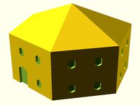
Prusa house
...prusa house
thingiverse
how prusa house could look like...
thingiverse
free

Prusa Mk2 "Fake Prusa" LCD cover by anraf1001
...r by anraf1001
thingiverse
version of prusa's lcd cover with "fake prusa" instead of "original prusa"
thingiverse
free
Prusa stabilizator by gutiueugen
...prusa stabilizator by gutiueugen
thingiverse
prusa stabilizator
thingiverse
free
Keychain Prusa by rbarbalho
...keychain prusa by rbarbalho
thingiverse
keychain with text prusa.
Original
3d_export
free
original table
...original table
3dexport
this is an original table with on one side a metallic square and on the other side a wood cylinder
design_connected
$16
Original beanbag
...designconnected
photo-realistic 3d models of the fatboy original beanbag for 3d architectural and interior design presentations.
turbosquid
$15
Original Gun
...squid
royalty free 3d model original gun for download as obj on turbosquid: 3d models for games, architecture, videos. (1483511)
turbosquid
$10
original faucet
...ree 3d model original faucet for download as ma, obj, and fbx on turbosquid: 3d models for games, architecture, videos. (1243295)
turbosquid
$30
original-armchairs
... available on turbo squid, the world's leading provider of digital 3d models for visualization, films, television, and games.
turbosquid
$29

Baileys Original
... available on turbo squid, the world's leading provider of digital 3d models for visualization, films, television, and games.
turbosquid
$20

Original Chair
... available on turbo squid, the world's leading provider of digital 3d models for visualization, films, television, and games.
turbosquid
$20

original-armchair
... available on turbo squid, the world's leading provider of digital 3d models for visualization, films, television, and games.
turbosquid
$12
Original Chair_039
... available on turbo squid, the world's leading provider of digital 3d models for visualization, films, television, and games.
turbosquid
$10

Sofia Original
... available on turbo squid, the world's leading provider of digital 3d models for visualization, films, television, and games.