GrabCAD
Things i did at school 4 (assemblies design and analysis)
by GrabCAD
Last crawled date: 1 year, 11 months ago
last 3 months in GMP
this time there is 2 categories, one of pure designing from specifications
and one of already existing mechanism study, mostly using solidworks simulations and meca3D
stress, energy and ecological simulations, in order to find solutions to improve the products
there is a lot to talk about, so I know no one will read everything, but if you are curious about one of the works, everything is listed under by chronological order, with how much time we had to do it, what we had to do, and what i ended up with
(sorry for all the .zip files, I had troubles uploading all of that in grabcad at once)
Designed :
1 tank caterpillar tension wheel bearing guiding (4h individual test) : because it was a test, I don’t have the original documents, but I tried to re-do the model from a pic of the subject I found online
We had to link the bearings and shaft to the caterpillar tension wheel, while making it dust proof and easy to lubricat
Left bearing is fixed only on it’s outter ring, while right bearing is completely fixed, with a little colar piece and a threaded part and lubrication goes through drilled holes in the shaft
But not much more to say
2 centrifugal pump shaft bearing guiding (4h) : once again, just guiding a shaft in a bore with bearings, had to be dust proof and could only drill in the given parts, not exiting yet
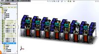
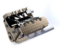
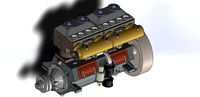
3 complete heavy duty speed reducer (16h + free time during a month) : that’s more interesting
Here it is a complete assembly to design from scratch, and I say heavy duty reducer, because it has to stand pretty big stresses, while not reducing much (really a reduced bearing, in the way that it has to bear huge loads)
But how much heavy duty it had to be wasn’t clear, we had to use conic roller bearing and oil drizzle (the most high end lubrication) and had load values, but no lifetime value…
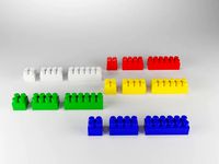
So I made 3 options with different bearing layout, one made to work fine for 120day of continuous load, one for 3 years and one for 20 years (on the picture, the 120day one has wrong gear thickness so it is too thin), I was first going with the 3 year one, but it used doubled bearing, and apparently we can’t do that, so I restarted from the beginning with the 120 day one
So we first had to define the gears, standing a 30HP motor at 1500rpm with a reduction of 0,7 some thing were fixed, some other calculated, but in the end we got helical gears, one with 26 tooth, the other with 37, 2,5mm of modulus, 70mm thick and 82mm between the two axis (so pretty tight to fit large bearings)
Then defining the bearings from the loads of 2Tons axial and 1,5Tons radial to the input and 5Tons axial and 2,5Tons radial to the output, that gave 62x25 and 90x32 bearings
And then around all that, do a casing with thick enough walls and the least surface to paint possible, and putting all the accessories for lubrication, lifting and holding
In the end I think it looks pretty cool, I don’t know if it would be usefull but at least it’s pretty…
visible in real time rendering here : https://sketchfab.com/models/468b0c584d94456bad4376d43eee7cca
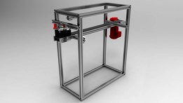
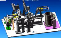
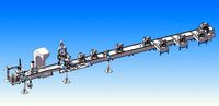
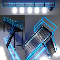
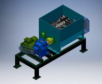
4 specialized machine for rubber profile cut control (16h + free time during a month) : the best work we had ^^ + with a person that actually work in specialized machine design
The goal of this machine, was to check the length of rubber profiles that has been cut from a previous machine, and come in from a conveyor, and also check the cut shape
For that we had to place 4 cameras above a conveyor that is faster than the previous one (to separate the profiles and be able to check their ends)
So we also had to power a conveyor for this machine and find a way to pull the profiles to get to it’s speed BUT the profiles can have different width, from 15 to 70mm, and length from 500 to 1200mm
So first I thought about where to place the cameras relative to the conveyor in order to get in focus, and have all possible lengths in frame (if you unhide the first part of the assembly, you can see the design driving sketches)
Then choosed the motor to power the conveyor and roller fixation + belt tension systems
And the best part : pulling straight the different sizes of profiles + I challenged myselft to use only 1 lower power motor
So, the idea is to have 2 belts at each side of the profile pulling it, the 2 belts need to be at the same speed but turning opposit ways
We could have used a gearing to change the rotation, and then another belt with a tension wheel to transfer the motion to the moving belt but that would have asked pretty large gears and there isn’t much room left to not block the sight of the cameras
So I found that it is possible to invert the motion by using the inside and the outside of a belt with 2 tension wheels to warp the transmission belt around the moving pulling belt
And to tune the width, I used a shaft with 2 thread in opposit ways, so when it is turned, the 2 pulling belt move symetrically
And the result is here : https://vid.me/M2u2
Then we had to attach everything together using aluminium profiles and make a parts list (nomenclature)
Analyzed :
1 toll booth gate openning mechanism (free time during a week) : here there was nothing to get in the end, it was just to practice on meca3D, and see what information this plugin can give us. i still uploaded it here because it is a cool mechanism than convert a full revolution in a smoothed start and stop quarter of revolution in one way and back
2 belt conveyor motor dimensioning (4h + free time during a week) : again, mostly software practice, this time using the feature of inputing curves as movement, speed or energy to any mechanical link of the assembly. but here there was a goal : finding out if the motor of a belt conveyor will undergo a power peak while starting the conveyor to get at it's normal speed, but since we only took into account the inertia of a planetary reductor compared to a fine torque (4Nm), we found that even an uselessly quick start didn't caused much of a peak (+1% of normal power when starting in 0,01 second)
so this simulation wasn't really reflecting the reality as the motor also has to launch the conveyor itself, rollers and things put on the conveyor
3 car gate cylinder placement (8h + free time during 2 week) : we had to find where to anchor the electric cylinder that move the gate, to lower the max needed energy for an openning in 8sec with wind (which has been simulated in 2 ways)
the first work was to find how to make the mechanism isostatic, because in the original, the cylinder was over constrained.
when that was done we have been able to simulated several positions for the cylinder(it was possible to move the body in 2 directions, and the piston end along the gate)
after several combinations, and using excel to visualize results better(the excel is uploaded here, but it’s pretty messy, there is pretty curves at least), i found out that moving the end of the piston anchor only changed the possible placement of the body anchor (with respect to the min and max length of the cylinder) it changed nothing to the requiered energy
then, i found that the body anchor was better to see in a polar coordinate system, because the angle with the gate hinge dictated the ration between the energy needed at the start and the end of the movement, while the distance between those two needed to be the greatest to give the cylinder the most effect
so, in the end, the best position was with the body anchor at 45° of the gate hinge, and then moved the piston end anchor to get the greatest distance between body anchor and gate hinge
about the wind, first, we just put a 200N force at the very end of the gate (arbitrary value), but when we found the best anchor positions, we had to make this more precise to get power value for the electric cylinder
we used the flow feature of meca3D, and played a bit with it too see what each value changed what
long story short, the 200N weren't that bad, but the value with wind as a flow was more around 130N but still not really certainly precise, the 200N is good, and so the cylinder had to produce ≈110W while consuming 250W of electricity (50% efficiency cylinder + losses in the linkages)
and with this power + the speed of the fluid inside the cylinder, it had to bear 31bar of pressure
4 piston segment mounting sensibility (4h) : this was done on a free but pretty dark (not userfriendly) software made by another school : RDM6. The goal was to know if, when mounting a piston segment by bending it around the head, is the segment about to break, or far from
in other words, do you have to be carefull while doing so, or not really
for that we had to measure a real piston segment, and find it’s material, and then find out how to simulated this shape in RDM6 “ossature” (which can only simulate beams of constant section)
we used a script that creat arcs from several beams
then how to simulate the stress of mounting the segment
for that we choosed to input a displacement of one end of the segment, so it can fit around the piston head that is larger than it’s initial inner diameter
and the simulation showed us that when the segment is right at the diameter of the piston head, it is already halfway from breaking apart, so, at least for this specific segment, you have to be very carefull when mounting it
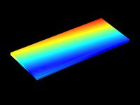
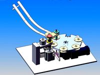
5 mechanical balance blade dimensioning (4h + free time during a week) : we are talking about the cheap mechanical balances that look like an alarm clock and with a bowl that is also used as a cover
We had to find the material and shape for the blades that bends to tell the weight in order to get a precision of 2% while standing up to 4kg
We did a simulation of the 4 blades with a weight at several places, and this showed us that the 4 blade get the same stress wherever the weight is
So we could work only on 1 blade
And we found that the thickness of the blade was the critical dimension, the one that had to be the most precise to be able to get a precise balance
And with the given values, in steel, the thickness had to be of 0,925mm but precise at ±0,012mm, while laminated blades can, at best, have ±0,5mm of variation in thickness
I found that it was possible to get the 2% only with really soft rubber blade (but this time more thick than wide)
In the softest rubber possible (Young modulus of 1MPa while steel was 200 000x over that) 12mm wide and 38mm “thick” and this was able to get ±0,5
But the most realistic conclusion is : those balance are not precise at all, like it could say 100g for something that weight 60g
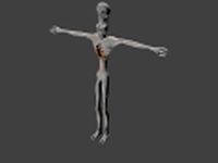
6 robot hand finger optimization (4h) : if you are extremly studious with my uploads (too much actually) , you will have noticed that this robot hand finger is from the robot hand of “things I did at school 1”
So here we had to find how to simulate the behavior of the finger under the maximum load and after that, find a more ecological solution than the actual fat steel finger
From the cylinder specifications and number of finger on the hand, we found that there can be up to 100N where the piston pulls
Then we prepared a solidworks simulation, with fixed geometry where an object would be handled, 100N where the piston pull and tell that there is an axis in the hole of the finger
Stress was very located, so we increased the node count around stressed area, and added filets where there would have been from manufacturing
And then I tried 2 solutions, one in ABS and one in aluminum
The ABS one mostly had a large fillet inside the finger, and was a 2mm thick hollow piece (rotomolded)
And the aluminum one was out of 2x 2mm thick plated cut, bent, and soldered to each other
When comparing the prices (very approximately) and the exological impacts, I found that the ABS solution was a bit better, but it might need to be coated to resist some things
7 rack gear tooth stresses (4h + free time during a week) : last one with RDM6, this time we had to prove the gear modulus dimensioning formula (based on breakage) m = 2,34 SQRT(T/k*σ) and overall, see what make a gear weak or strong
From the geometry of a cut gear, we had to put the right force, and the right place, with the right orientation (right force was based on the formula)
And in a nutsheel we found that to make it stronger we can make it fatter, use lubricant, or harden the material, and also don’t go to the formula limit because it doesn’t take any security coefficient into account
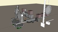
8 stresses and energies in a Segway® (12h + free time during a month, which wasn’t that much with internship search) : back to meca3D, here the model and simulation was already made, we “just” had to find how much power the motor needed to produce, in relation the the road orientation, and how to make the handlebar more ecological
But we took waaay too much time trying to make a simulation with a curves road, and didn’t succeeded
Otherwise we found that on a flat road and normal driving, the motor had to produce 1kW with 1,6kW peaks and the handlebar had to stand up to 65Nm (when leaning harshly)
We made a simulation where the road was going up by changing the orientation of the gravitational force, but because the driver was leaning the same way, motor power didn’t changed, but the segway didn’t go very far (didn’t had time to try and get the same distance for the same time and see the power difference)
And the handlebar could be better off simply with a smoother shape (more geometrical strength, so with a fixed stress, the weight could have been lowered)
this time there is 2 categories, one of pure designing from specifications
and one of already existing mechanism study, mostly using solidworks simulations and meca3D
stress, energy and ecological simulations, in order to find solutions to improve the products
there is a lot to talk about, so I know no one will read everything, but if you are curious about one of the works, everything is listed under by chronological order, with how much time we had to do it, what we had to do, and what i ended up with
(sorry for all the .zip files, I had troubles uploading all of that in grabcad at once)
Designed :
1 tank caterpillar tension wheel bearing guiding (4h individual test) : because it was a test, I don’t have the original documents, but I tried to re-do the model from a pic of the subject I found online
We had to link the bearings and shaft to the caterpillar tension wheel, while making it dust proof and easy to lubricat
Left bearing is fixed only on it’s outter ring, while right bearing is completely fixed, with a little colar piece and a threaded part and lubrication goes through drilled holes in the shaft
But not much more to say
2 centrifugal pump shaft bearing guiding (4h) : once again, just guiding a shaft in a bore with bearings, had to be dust proof and could only drill in the given parts, not exiting yet
3 complete heavy duty speed reducer (16h + free time during a month) : that’s more interesting
Here it is a complete assembly to design from scratch, and I say heavy duty reducer, because it has to stand pretty big stresses, while not reducing much (really a reduced bearing, in the way that it has to bear huge loads)
But how much heavy duty it had to be wasn’t clear, we had to use conic roller bearing and oil drizzle (the most high end lubrication) and had load values, but no lifetime value…
So I made 3 options with different bearing layout, one made to work fine for 120day of continuous load, one for 3 years and one for 20 years (on the picture, the 120day one has wrong gear thickness so it is too thin), I was first going with the 3 year one, but it used doubled bearing, and apparently we can’t do that, so I restarted from the beginning with the 120 day one
So we first had to define the gears, standing a 30HP motor at 1500rpm with a reduction of 0,7 some thing were fixed, some other calculated, but in the end we got helical gears, one with 26 tooth, the other with 37, 2,5mm of modulus, 70mm thick and 82mm between the two axis (so pretty tight to fit large bearings)
Then defining the bearings from the loads of 2Tons axial and 1,5Tons radial to the input and 5Tons axial and 2,5Tons radial to the output, that gave 62x25 and 90x32 bearings
And then around all that, do a casing with thick enough walls and the least surface to paint possible, and putting all the accessories for lubrication, lifting and holding
In the end I think it looks pretty cool, I don’t know if it would be usefull but at least it’s pretty…
visible in real time rendering here : https://sketchfab.com/models/468b0c584d94456bad4376d43eee7cca
4 specialized machine for rubber profile cut control (16h + free time during a month) : the best work we had ^^ + with a person that actually work in specialized machine design
The goal of this machine, was to check the length of rubber profiles that has been cut from a previous machine, and come in from a conveyor, and also check the cut shape
For that we had to place 4 cameras above a conveyor that is faster than the previous one (to separate the profiles and be able to check their ends)
So we also had to power a conveyor for this machine and find a way to pull the profiles to get to it’s speed BUT the profiles can have different width, from 15 to 70mm, and length from 500 to 1200mm
So first I thought about where to place the cameras relative to the conveyor in order to get in focus, and have all possible lengths in frame (if you unhide the first part of the assembly, you can see the design driving sketches)
Then choosed the motor to power the conveyor and roller fixation + belt tension systems
And the best part : pulling straight the different sizes of profiles + I challenged myselft to use only 1 lower power motor
So, the idea is to have 2 belts at each side of the profile pulling it, the 2 belts need to be at the same speed but turning opposit ways
We could have used a gearing to change the rotation, and then another belt with a tension wheel to transfer the motion to the moving belt but that would have asked pretty large gears and there isn’t much room left to not block the sight of the cameras
So I found that it is possible to invert the motion by using the inside and the outside of a belt with 2 tension wheels to warp the transmission belt around the moving pulling belt
And to tune the width, I used a shaft with 2 thread in opposit ways, so when it is turned, the 2 pulling belt move symetrically
And the result is here : https://vid.me/M2u2
Then we had to attach everything together using aluminium profiles and make a parts list (nomenclature)
Analyzed :
1 toll booth gate openning mechanism (free time during a week) : here there was nothing to get in the end, it was just to practice on meca3D, and see what information this plugin can give us. i still uploaded it here because it is a cool mechanism than convert a full revolution in a smoothed start and stop quarter of revolution in one way and back
2 belt conveyor motor dimensioning (4h + free time during a week) : again, mostly software practice, this time using the feature of inputing curves as movement, speed or energy to any mechanical link of the assembly. but here there was a goal : finding out if the motor of a belt conveyor will undergo a power peak while starting the conveyor to get at it's normal speed, but since we only took into account the inertia of a planetary reductor compared to a fine torque (4Nm), we found that even an uselessly quick start didn't caused much of a peak (+1% of normal power when starting in 0,01 second)
so this simulation wasn't really reflecting the reality as the motor also has to launch the conveyor itself, rollers and things put on the conveyor
3 car gate cylinder placement (8h + free time during 2 week) : we had to find where to anchor the electric cylinder that move the gate, to lower the max needed energy for an openning in 8sec with wind (which has been simulated in 2 ways)
the first work was to find how to make the mechanism isostatic, because in the original, the cylinder was over constrained.
when that was done we have been able to simulated several positions for the cylinder(it was possible to move the body in 2 directions, and the piston end along the gate)
after several combinations, and using excel to visualize results better(the excel is uploaded here, but it’s pretty messy, there is pretty curves at least), i found out that moving the end of the piston anchor only changed the possible placement of the body anchor (with respect to the min and max length of the cylinder) it changed nothing to the requiered energy
then, i found that the body anchor was better to see in a polar coordinate system, because the angle with the gate hinge dictated the ration between the energy needed at the start and the end of the movement, while the distance between those two needed to be the greatest to give the cylinder the most effect
so, in the end, the best position was with the body anchor at 45° of the gate hinge, and then moved the piston end anchor to get the greatest distance between body anchor and gate hinge
about the wind, first, we just put a 200N force at the very end of the gate (arbitrary value), but when we found the best anchor positions, we had to make this more precise to get power value for the electric cylinder
we used the flow feature of meca3D, and played a bit with it too see what each value changed what
long story short, the 200N weren't that bad, but the value with wind as a flow was more around 130N but still not really certainly precise, the 200N is good, and so the cylinder had to produce ≈110W while consuming 250W of electricity (50% efficiency cylinder + losses in the linkages)
and with this power + the speed of the fluid inside the cylinder, it had to bear 31bar of pressure
4 piston segment mounting sensibility (4h) : this was done on a free but pretty dark (not userfriendly) software made by another school : RDM6. The goal was to know if, when mounting a piston segment by bending it around the head, is the segment about to break, or far from
in other words, do you have to be carefull while doing so, or not really
for that we had to measure a real piston segment, and find it’s material, and then find out how to simulated this shape in RDM6 “ossature” (which can only simulate beams of constant section)
we used a script that creat arcs from several beams
then how to simulate the stress of mounting the segment
for that we choosed to input a displacement of one end of the segment, so it can fit around the piston head that is larger than it’s initial inner diameter
and the simulation showed us that when the segment is right at the diameter of the piston head, it is already halfway from breaking apart, so, at least for this specific segment, you have to be very carefull when mounting it
5 mechanical balance blade dimensioning (4h + free time during a week) : we are talking about the cheap mechanical balances that look like an alarm clock and with a bowl that is also used as a cover
We had to find the material and shape for the blades that bends to tell the weight in order to get a precision of 2% while standing up to 4kg
We did a simulation of the 4 blades with a weight at several places, and this showed us that the 4 blade get the same stress wherever the weight is
So we could work only on 1 blade
And we found that the thickness of the blade was the critical dimension, the one that had to be the most precise to be able to get a precise balance
And with the given values, in steel, the thickness had to be of 0,925mm but precise at ±0,012mm, while laminated blades can, at best, have ±0,5mm of variation in thickness
I found that it was possible to get the 2% only with really soft rubber blade (but this time more thick than wide)
In the softest rubber possible (Young modulus of 1MPa while steel was 200 000x over that) 12mm wide and 38mm “thick” and this was able to get ±0,5
But the most realistic conclusion is : those balance are not precise at all, like it could say 100g for something that weight 60g
6 robot hand finger optimization (4h) : if you are extremly studious with my uploads (too much actually) , you will have noticed that this robot hand finger is from the robot hand of “things I did at school 1”
So here we had to find how to simulate the behavior of the finger under the maximum load and after that, find a more ecological solution than the actual fat steel finger
From the cylinder specifications and number of finger on the hand, we found that there can be up to 100N where the piston pulls
Then we prepared a solidworks simulation, with fixed geometry where an object would be handled, 100N where the piston pull and tell that there is an axis in the hole of the finger
Stress was very located, so we increased the node count around stressed area, and added filets where there would have been from manufacturing
And then I tried 2 solutions, one in ABS and one in aluminum
The ABS one mostly had a large fillet inside the finger, and was a 2mm thick hollow piece (rotomolded)
And the aluminum one was out of 2x 2mm thick plated cut, bent, and soldered to each other
When comparing the prices (very approximately) and the exological impacts, I found that the ABS solution was a bit better, but it might need to be coated to resist some things
7 rack gear tooth stresses (4h + free time during a week) : last one with RDM6, this time we had to prove the gear modulus dimensioning formula (based on breakage) m = 2,34 SQRT(T/k*σ) and overall, see what make a gear weak or strong
From the geometry of a cut gear, we had to put the right force, and the right place, with the right orientation (right force was based on the formula)
And in a nutsheel we found that to make it stronger we can make it fatter, use lubricant, or harden the material, and also don’t go to the formula limit because it doesn’t take any security coefficient into account
8 stresses and energies in a Segway® (12h + free time during a month, which wasn’t that much with internship search) : back to meca3D, here the model and simulation was already made, we “just” had to find how much power the motor needed to produce, in relation the the road orientation, and how to make the handlebar more ecological
But we took waaay too much time trying to make a simulation with a curves road, and didn’t succeeded
Otherwise we found that on a flat road and normal driving, the motor had to produce 1kW with 1,6kW peaks and the handlebar had to stand up to 65Nm (when leaning harshly)
We made a simulation where the road was going up by changing the orientation of the gravitational force, but because the driver was leaning the same way, motor power didn’t changed, but the segway didn’t go very far (didn’t had time to try and get the same distance for the same time and see the power difference)
And the handlebar could be better off simply with a smoother shape (more geometrical strength, so with a fixed stress, the weight could have been lowered)
Similar models
grabcad
free

Belt Conveyor
...belt conveyor
grabcad
one segment of construction for rubber belt conveyor.
thingiverse
free

Timing gear M8 T2.5 64 tooth 50mm by tmackay
...n, so the pulley was the only new component to print.
though i did have to order in the timing belt, t2.5 - 6mm wide, 200mm long.
grabcad
free

Hydraulic Piston
...es the inside of the cylinder into two chambers, the bottom chamber (cap end) and the piston rod side chamber (rod end/head-end).
3dwarehouse
free
SketchyPhysics example - Workshop
... gear. this is a older example so the joints look different. sketchyphysics is a ruby plugin for google sketchup. #sketchyphysics
grabcad
free

Simple lightweight truck underrun protection
...with simscale the high stressed dot was gone. so i am sure that the dot will disappear when the model is simulated with simscale.
thingiverse
free

Prusa i3 Y axis belt anchor by wayne69x
...i re designed the anchor to have a screw clamp to securely attach belts. cable ties are just used to keep belt ends from rubbing.
grabcad
free

conveyor belt
...by motor power, manpower and gravitational force. conveyor is the mechanism that minimizes manpower in handling and transferring.
grabcad
free

Flat PVC Belt Conveyor
...t about to travel over through tension bearing supported at the other end also had the polymer side guides around.
try making it.
grabcad
free

2 Stage Reduction Gear Box
...ge reduction gear box
grabcad
a simple gear box used to reduce and deliver the power from an electrical motor to a conveyor belt
grabcad
free

Is belt and conveyor same or different?
...many types of conveyor systems. ... one or both of the pulleys are powered, moving the belt and the material on the belt forward.
Analysis
turbosquid
$15

Test tubes analysis
...lysis for download as blend, 3dm, 3ds, dae, fbx, obj, and stl on turbosquid: 3d models for games, architecture, videos. (1608711)
3d_export
$5
wind turbine
...turbine and can be used by students for their analysis projects using...
3d_export
free
lumped vehicle suspension system
...lumped vehicle suspension system 3dexport lumped_vehicle_suspension_system analysis by comsol.<br>accurate results can be taken by just changing...
3d_ocean
$6
Chairs and Table
...blender 3d. exported to different formats: .obj;.3ds;.blend;.dae;.fbx;.ply;.x3d;.mtl . site analysis ...
3d_export
$10
Recessed shell bitts
...coating etc are optional; 3.one year quality warranty; 4.chemical analysis report 5.dimensional as-built...
3d_ocean
$35
subsea oil or gaz production
...subsea oil or gaz production 3docean analysis earth's interior gas gas company gas industry industry marine...
3d_export
$12
perfect shaped skull basemesh
...by reference references and photos, but also by comparative analysis with many references made using photogrammetry<br>clean topology, no errors,...
3d_export
$5
laptop chair
...steel material, and as you can see in the analysis static picture this model can bear up to 200kg...
3d_export
$10

ornamental desk cannon
...for 3d printing or to be used in motion analysis hope you find it useful! format: 3ds, 3mf, acis,...
3d_export
$100
turbine a gaz 9fa general electrique
...on the general eclectic 9fa turbine in the static analysis only the vane part is shown when examining the...
School
3d_export
$5

school
...school
3dexport
school
3d_ocean
$19

school bus
...school bus
3docean
bus school school bus students vehicle
school bus
3d_export
$7

school
...n twinmotion 2019. this 3d model includes: floor plans of school on revit file and contains other formats: .fbx, .rvt, .tm files.
turbosquid
$99

School
...
turbosquid
royalty free 3d model school for download as max on turbosquid: 3d models for games, architecture, videos. (1332866)
turbosquid
$79

School
...
turbosquid
royalty free 3d model school for download as max on turbosquid: 3d models for games, architecture, videos. (1244659)
turbosquid
$29

School
...
turbosquid
royalty free 3d model school for download as max on turbosquid: 3d models for games, architecture, videos. (1556196)
turbosquid
$3

school
...alty free 3d model school for download as obj, fbx, and blend on turbosquid: 3d models for games, architecture, videos. (1345052)
turbosquid
$129

School
... available on turbo squid, the world's leading provider of digital 3d models for visualization, films, television, and games.
turbosquid
$100

School
... available on turbo squid, the world's leading provider of digital 3d models for visualization, films, television, and games.
turbosquid
$10

school
... available on turbo squid, the world's leading provider of digital 3d models for visualization, films, television, and games.
Did
turbosquid
free

ouch did I just step on glass?
...e 3d model ouch did i just step on glass? for download as stl on turbosquid: 3d models for games, architecture, videos. (1554279)
3d_export
free

shaman
...hi and this is my first 3d project, i did it for a long time, interesting, download...
3d_export
$10

shotmass effect
...shotmass effect 3dexport to be honest i did not understand what kind of it was because i...
3d_export
$9

Scarecrow
...scarecrow 3dexport i did this file in zbrush , here is zbrush obj...
3d_export
$5

camera
...textures need to be tweaked a little (because, i did everything in a...
3ddd
$1

table and chair manufacturer israel
...table and chair manufacturer israel 3ddd обеденный i had did this table and chair for manufucturer from...
3d_export
$25

cat woman
...cat woman 3dexport i did this file in zbrush here is stl obj fbx...
3d_export
$12

corpse bride
...corpse bride 3dexport i did this file in zbrush , here is ztl obj...
3d_export
$5

child bed
...child bed 3dexport child bed in real size. i did it in real life for my daughter using that...
3d_export
$6

Alien
...alien 3dexport alien character i recently did for sci-fi animation. used blender eevee render engine. not...
Assemblies
3d_export
$7
Electronic product assembly machine assembly machine
...electronic product assembly machine assembly machine
3dexport
electronic product assembly machine assembly machine
3d_export
$15
generator assembly line
...ced and assembled in the form of module block. it is a demonstration project of generator assembly. welcome to download and learn
3d_export
$10
elevator traction machine assembly line motor assembly process
... traction machine assembly line motor assembly process
3dexport
elevator traction machine assembly line (motor assembly process)
3d_export
$16
pin assembly machine
...pin assembly machine
3dexport
pin assembly machine
3d_export
$7
tower-crane-assembly
...tower-crane-assembly
3dexport
tower-crane-assembly
turbosquid
$100

Engine Assembly
...id
royalty free 3d model engine assembly for download as stl on turbosquid: 3d models for games, architecture, videos. (1658296)
turbosquid
$100

Engine Assembly
...id
royalty free 3d model engine assembly for download as stl on turbosquid: 3d models for games, architecture, videos. (1658293)
turbosquid
$100
Engine Assembly
...id
royalty free 3d model engine assembly for download as stl on turbosquid: 3d models for games, architecture, videos. (1658291)
turbosquid
$75
Platform Assembly
...royalty free 3d model platform assembly for download as blend on turbosquid: 3d models for games, architecture, videos. (1472939)
turbosquid
$15
generator assembly
...y free 3d model generator assembly for download as and sldas on turbosquid: 3d models for games, architecture, videos. (1469469)
Things
turbosquid
free

spinny thing
...ng
turbosquid
free 3d model spinny thing for download as max on turbosquid: 3d models for games, architecture, videos. (1414103)
turbosquid
$9

The decorated Thing
...royalty free 3d model the decorated thing for download as obj on turbosquid: 3d models for games, architecture, videos. (1634636)
turbosquid
$2

HORROR THINGS
...quid
royalty free 3d model horror things for download as fbx on turbosquid: 3d models for games, architecture, videos. (1316296)
turbosquid
$1
Stone things
...osquid
royalty free 3d model stone things for download as ma on turbosquid: 3d models for games, architecture, videos. (1252237)
turbosquid
$90

the thing - Vyzandan
... available on turbo squid, the world's leading provider of digital 3d models for visualization, films, television, and games.
turbosquid
free

Yellow Thing
... available on turbo squid, the world's leading provider of digital 3d models for visualization, films, television, and games.
turbosquid
free

Ball Thing
... available on turbo squid, the world's leading provider of digital 3d models for visualization, films, television, and games.
3d_export
$20
The Thing 3D Model
...the thing 3d model
3dexport
slender alien horror monster enemy scary
the thing 3d model ileon18 99013 3dexport
3d_ocean
$5

Marvel Comics Thing
... poly count (triangles): 4056. files : .obj (multi format), .3ds (multi format), .fbx (multi format), .max (2011-2012-2013-2014).
3d_export
$5

the thing
...d and animated with meta-rig<br>particle system hair for fur<br>blend,fbx,obj,colada and abc files<br>unwrapped
4
turbosquid
$9

Office Chair 4-4
... available on turbo squid, the world's leading provider of digital 3d models for visualization, films, television, and games.
3d_export
$5
doors- 4
...doors- 4
3dexport
doors 4
3d_export
$5
hinge 4
...hinge 4
3dexport
hinge 4
3ddd
$1

Штора №4
...штора №4
3ddd
штора №4
3d_export
free
playstation 4
...playstation 4
3dexport
playstation 4
turbosquid
$1
re 4-4 electric locomotive
... free 3d model re 4 4 electric locomotive for download as obj on turbosquid: 3d models for games, architecture, videos. (1707845)
3ddd
$1

nexus 4
...nexus 4
3ddd
lg , телефон
nexus 4
3ddd
$1
4 Poufs
...4 poufs
3ddd
пуф
4 soft poufs
turbosquid
$12

Calligraphic Digit 4 Number 4
...hic digit 4 number 4 for download as max, obj, fbx, and blend on turbosquid: 3d models for games, architecture, videos. (1389332)
3ddd
$1
Dauphin 4+
...dauphin 4+
3ddd
кресло
dauphin 4+ конференц кресло
Design
3ddd
$1

LINE DESIGN (Doors Design)
...line design (doors design)
3ddd
дверь
modern doors design - line design concept
turbosquid
$5

designer
...alty free 3d model designer for download as max, obj, and fbx on turbosquid: 3d models for games, architecture, videos. (1422665)
3ddd
$1

VER DESIGN
...ver design
3ddd
ver design
кресло ver design
3ddd
$1

VER DESIGN
...ver design
3ddd
ver design
диван ver design
3ddd
$1
Bagno design
...bagno design
3ddd
bagno design , унитаз
санитария bagno design
3ddd
free

VER DESIGN
...ver design
3ddd
ver design , стеллаж
полка ver design
3ddd
$1
VER DESIGN
...ver design , лежак , шезлонг
шезлонг ver design
3d_export
free
designer
..., trees and much more. the model has 3 types of parts: - 4 cells - 6 cells - 8 cells the *.max file contains 5 colored materials.
3d_export
$19

level design
...level design
3dexport
you can use this design (level design) in your own game.
3d_export
$7
Crusher design
...crusher design
3dexport
crusher design