Thingiverse
The Histed Dial by jonnyhifi
by Thingiverse
Last crawled date: 4 years, 8 months ago
An Actual physical Bed levelling tool for a Prusa i3 mk3 printer - for use with wavey washers etc- as per https://github.com/PrusaOwners/prusaowners/wiki/Bed_Leveling_with_Wave_Springs
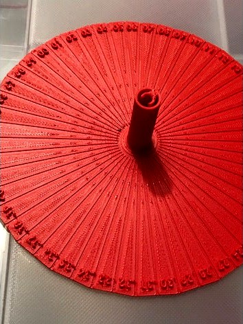
My first 3d CAD design ever - I feel I need to level my mk3’s bed (it has a maximum height level change across it of .67mm) - i have read the Wikipedia article - and reckon adjusting the bed m3 screws “a specific smidge” will be pretty hard - so designed a screwdriver gauge for a standard pitch m3 screw (ie .5mm height change per turn), that means every 50th of a Turn, the screw changes its height .01mm - an accuracy on the edge of achievable from what I read. This guage allows you to see the height change as you turn a screw.
There are 9 screws holding down the heated bed that need to be adjusted very precisely. DO NOT DO THIS UNLESS YOU'VE READ THE WIKIPEDIA ARTICLE AND KNOW WHAT YOU ARE ATTEMPTING.
My design clips onto my Wera M3 screwdriver (it is a 2mm head, and it has a 3mm cylindrical shaft and is the best M3 screwdriver I have-as in the pictures).
It has a clip feature that works really well to my surprise and doesn’t slip - yet can be removed/ attached firmly, easily. you put the screwdriver down the vertical hole in the tool, the push it firmly at the top into the clip, and at the bottom into the clip.
You really want the screwdriver in the clip : as then the centre of the dial is perfectly aligned with the centre of the shaft , so the circumference of the dial will rotate about its centre in use rather than being eccentric, and the base will be perpendicular to the screwdriver, so helps you align the screwdriver perfectly perpendicular to the screw head.
Mount the dial so the tip of the screwdriver just clears the base of the dial. (less than a millimetre-just enough to properly engage with a screw head) This is so the dial is almost touching the bed of the printer when the screwdriver is in the head of a screw, and the screen printed dotted lines on the heated bed give you a nice reference against the dial as you turn it, so you can see how much you've turned the screwdriver, and the resultant height change in the screw as you turn it.
You'll find there's slop in the screwdriver bit interface with the screw : this is due to manufacturing tolerances (hopefully not damaged screwdriver or screws !), obviousy take the slop up before you start judging how much you've turned your screw.
Use the screwdriver normally : i.e. turn the screwdriver by the screwdriver : not the dial. The dial will not grip the screwdriver well enough to turn it without it slipping, which you won't then be able to see.
The text on the dial indicates Mm height change, as you rotate the screw - against a reference on the bed (eg the white lines). There are 50 radial “spokes” to help you see where you are.
I printed mine in red Asa extrafill, standard prusa profile. I updated the files in light of what I printed prior to upload of the STL. I didn't make any change to the clip feature as that worked perfectly :I added some more text to make the ".1" increments more obvious, my name, the pitch of the screw it's for, and changed the outer shape to circular (I had made it a 25 sided polygon : but that just made it look wonky rather than being helpful, and obviously the "spokes" wouldn't then align properly as it rotated with bed reference marks). Any filament should be fine : it's not like this sees any mechanical load. One point to note : I printed a prototype section in black ASA : the text was almost unreadable, so I swapped to the light colour which made it way more readable. (light hitting the letters casts a slight shadow : so if on black plastic the shadows are almost invisible, and hence produce no contrast, ie.contrast is gone, and hence they are less visible).
It will work for 8 of the 9 screws easily (you may have to move the bed for and aft along the y axis to get to them). The 9th a the back by the heated bed power lead you'll have to have the gauge set a little higher on the screwdriver to clear. (vertically).
If people like this but use other screwdrivers, I'm happy to do some different versions for different diameter screwdriver driving shafts. I simply made it for the best one I had. I have no idea how common the 3mm dimension is.
I'd use the 3mf file rather than the STL : the file format of 3MF is way better than the STL one. but hey, thingiverse insists on an STL to actually publish this... so here it is.
Ironically I haven't actually used it yet, as I have a ton of work which has got in the way of actually doing the job. Do give me feedback as to how you get on. I've posted this so swiftly due to people asking on the facebook prusa community forum : and I wanted to reciprocate some opensource love which has helped me so much. I hope to update this once I have used it! Thank you everyone.
Any advice on the slightly manky surface texture I’d be interested to hear. Over extrusion ? (At the end of surface infill where it stops there’s a raised bit on each “spoke” which should be flat) I had calibrated extrusion multiplier with a 25mm cube sidewall ..(came out at 1.085)