Thingiverse
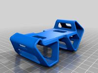
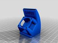
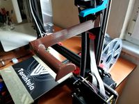
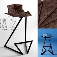
Tevo Tornado - belt-driven 2-nd Z-rod with minimal parts by AlMuz
by Thingiverse
Last crawled date: 3 years ago
WARNING
This mod reduces max print height by 4..8 mm
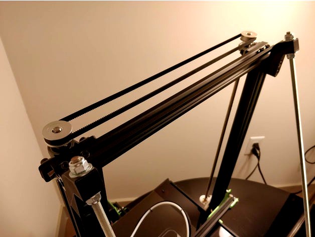
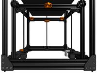
Single motor belt-driven design is better than two separate motors that will always have de-sync issues. That was the reason why I've picked Tornado over CR-10S (price the same, but AC heat-bed is a big win). I've decided to go with slightly simpler and cleaner design of the belt-driven second Z-rod for Tevo Tornado at the expense of slightly more complicated assembly:
Doesn't incorporate belt-tensioner (that used in other similar designs).
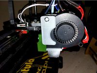
Both rods are suspended from the top by set-screws of pillow-block bearings, instead of being supported by the motor axle(s) and coupler(s) at the bottom. This approach completely eliminates Z bending and elephant foot artifacts on 3D prints. I can finally see distinctive second layer when printing (instead of nozzle messing the groves in the first layer).
Less parts, at the expense of slightly more complicated assembly process, but this also means somewhat faster assembly!
Additional hardware needed:
A set of 600 mm T8 lead screw rod with nut and 2x pillow-block bearings. Like this one: https://www.ebay.com/itm/T8-600mm-Stainless-Steel-Lead-Screw-Set-with-Mounted-Ball-Bearing-and-Shaft/173414745777
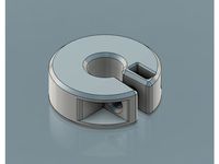
2x 40T GT2 pulleys - bigger diameter gives bigger precision of alignment between two rods. You can also 3D-print these and save some money.
784-2GT closed loop belt. Required tooth count depends on the diameter of pulleys, so if you get longer belt - you have to get/print bigger diameter pulley with more teeth.
4x M5 sliding T-nuts (like on a picture)
4x M5 20mm bolts
6x M3 12mm bolts
6x M3 nuts
12x M3 washers
Assembly Instructions
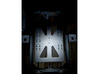
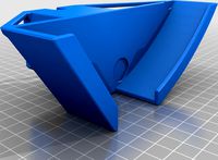
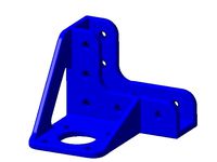
Part 1 - 3D-printed back-plate assembly
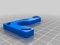
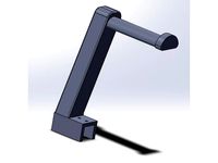
Pre-assemble the 3D-printed back-plate with the lead-screw nut on 90-deg mount using M3 bolts, nuts and washers. But don't tighten-up too much. You will need to slide the components later to align the 2-nd Z-rod vertically to the top-mounted pillow-block bearing.
To mount the 3D-printed back-plate assembly - you use the same nuts that hold the roller wheels in place. Instead of turning the nuts you will turn the bolts with allen key from the opposite side of the rollers assembly. However to get an access to the bolt of inner roller you have to remove the whole aluminum plate from the gantry - this is the most complicated part in the whole assembly process.
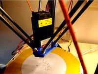
Part 2 - Replacing the original Z-rod on the motor side
After the 3D-printed back-plate assembly in place - remove the original top bearing assembly on the motor side.
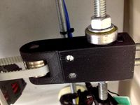
Install the 1-st pillow block bearing using 3D-printed spacer. It should be aliened properly with the stepper motor axle and the original rod. If not aligned - you will need to print a different spacer of different height (scale the spacer part by Z and print it again).Tevo Tornado works OK without top-bearing in place. So just remove the pillow block and print another spacer (no need to reinstall original bearing assembly).
When 1-st block bearing installed - remove the original rod and insert the new 600 mm rod instead. Put the 40T pulley on top to measure the left-over height.
Remove the rod, cut it to the required length by hacksaw and install it back.
!!! NOTE !!! that properly installed Z-rod on the motor side should be suspended by set-screw of the pillow-block bearing on top. It must NOT be fully inserted into the coupler (when its end hits the coupler internals or motor axle). There should be like 1..2 mm gap inside, so the coupler will allow motor axle and the rod to float relatively to each other. Otherwise metal parts of the coupler, motor axle and the rod will rub each other, what may produce artifacts on printed parts due to Z-bending.
Don't install the 40T pulley on the motor-side yet, it is the last step of the assembly process.
Tighten up the set-screws and spacer bolts of the pillow-block bearing. Tighten-up the set screws of the shaft coupler to the motor at the bottom. Make sure that your printer still works with one axis installed on the motor side and 3D-printed back-plate assembly on the another side.
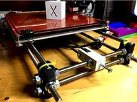
Part 3 - Installing 2-nd Z-rod with the belt and pulleys
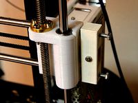
Install the 2-nd pillow-block bearing in place using one more 3D-printed spacer, but don't tighten up the spacer bolts too much yet (you will slide it to adjust the belt tension).
Insert the original rod in it (the one you took off from the motor side). Fix the rod with a set-screws of the pillow-block bearing leaving enough length to install the 40T pulley on top.
Move the X-axis assembly to the very bottom (this will minimize the alignment errors).
Align the vertical position of the rod adjusting the 90-deg nut-mount on the 3D-printed back-plate assembly. But don't tighten up M3 screws yet (we still have to set correct distance between rods for the belt tension)!!!
Now you should have both Z rods installed on pillow-block bearings (suspended from the top by set-screws). Both pulleys should be removed. Its time to measure and set the correct distance between the rods to get good belt tension.
Take the closed loop 784T GT2 belt. Grab 40T pulleys (one in each hand) and hook the belt on them. Stretch the belt with pulleys. Use the distance between bores of the pulleys as an improvised ruler to measure the distance between the rods.
Shift the 2-nd Z pillow-block bearing (non-motor side) so that the distance between rods would be 3..5 mm longer than what an improvised stretched-belt ruler shows you.
Don't install the pulleys with the belt before shifting the pillow-block bearing - you will never get enough belt tension if the belt already installed.
When rod distance is set - tighten up the spacer bolts of the pillow block bearing.
Re-align the 2-nd Z-rod vertically again adjusting the 90-deg nut-mount on the 3D-printed back-plate assembly. Tighten up the M3 botls and nuts of the 3D-printed back-plate assembly.
Now its time to set the pulleys with belt on the Z-rods. To do that - hook the belt over the pulleys and stretch them apart (like you did for distance measurement between rods). Set one pulley on the motor-side rod by 4..5 mm (not fully), then stretch the belt with another pulley to the second Z-rod and set it the rod (also by 4...6 mm). So that horisontaly they are on the same level. You should feel the the belt has good enough tension (produces very low tone note as a guitar string). If you unable to hop the second pulley on the second Z - than the rods are too far away from each other (unscrew the 2nd Z-spacer and realign everything again).
Slide both pulleys simultaneously down until they rest on pillow-block bearings. Tighten-up the set screws on the motor-side only, leaving another side loose (you have to level the X-axis assembly first).
Use a square ruler to make sure that the alu extrusion of the X-axis assembly is perpendicular to both vertical alu extrusions of the Z-assembly. Rotate the 2-nd Z-rod to adjust the X-axis angle relatively to vertical extrusions. When set perfectly square - tighten-up the set-screws of the 40T puley on the 2-nd Z rod.
Level the bed and run a test print!
This mod reduces max print height by 4..8 mm
Single motor belt-driven design is better than two separate motors that will always have de-sync issues. That was the reason why I've picked Tornado over CR-10S (price the same, but AC heat-bed is a big win). I've decided to go with slightly simpler and cleaner design of the belt-driven second Z-rod for Tevo Tornado at the expense of slightly more complicated assembly:
Doesn't incorporate belt-tensioner (that used in other similar designs).
Both rods are suspended from the top by set-screws of pillow-block bearings, instead of being supported by the motor axle(s) and coupler(s) at the bottom. This approach completely eliminates Z bending and elephant foot artifacts on 3D prints. I can finally see distinctive second layer when printing (instead of nozzle messing the groves in the first layer).
Less parts, at the expense of slightly more complicated assembly process, but this also means somewhat faster assembly!
Additional hardware needed:
A set of 600 mm T8 lead screw rod with nut and 2x pillow-block bearings. Like this one: https://www.ebay.com/itm/T8-600mm-Stainless-Steel-Lead-Screw-Set-with-Mounted-Ball-Bearing-and-Shaft/173414745777
2x 40T GT2 pulleys - bigger diameter gives bigger precision of alignment between two rods. You can also 3D-print these and save some money.
784-2GT closed loop belt. Required tooth count depends on the diameter of pulleys, so if you get longer belt - you have to get/print bigger diameter pulley with more teeth.
4x M5 sliding T-nuts (like on a picture)
4x M5 20mm bolts
6x M3 12mm bolts
6x M3 nuts
12x M3 washers
Assembly Instructions
Part 1 - 3D-printed back-plate assembly
Pre-assemble the 3D-printed back-plate with the lead-screw nut on 90-deg mount using M3 bolts, nuts and washers. But don't tighten-up too much. You will need to slide the components later to align the 2-nd Z-rod vertically to the top-mounted pillow-block bearing.
To mount the 3D-printed back-plate assembly - you use the same nuts that hold the roller wheels in place. Instead of turning the nuts you will turn the bolts with allen key from the opposite side of the rollers assembly. However to get an access to the bolt of inner roller you have to remove the whole aluminum plate from the gantry - this is the most complicated part in the whole assembly process.
Part 2 - Replacing the original Z-rod on the motor side
After the 3D-printed back-plate assembly in place - remove the original top bearing assembly on the motor side.
Install the 1-st pillow block bearing using 3D-printed spacer. It should be aliened properly with the stepper motor axle and the original rod. If not aligned - you will need to print a different spacer of different height (scale the spacer part by Z and print it again).Tevo Tornado works OK without top-bearing in place. So just remove the pillow block and print another spacer (no need to reinstall original bearing assembly).
When 1-st block bearing installed - remove the original rod and insert the new 600 mm rod instead. Put the 40T pulley on top to measure the left-over height.
Remove the rod, cut it to the required length by hacksaw and install it back.
!!! NOTE !!! that properly installed Z-rod on the motor side should be suspended by set-screw of the pillow-block bearing on top. It must NOT be fully inserted into the coupler (when its end hits the coupler internals or motor axle). There should be like 1..2 mm gap inside, so the coupler will allow motor axle and the rod to float relatively to each other. Otherwise metal parts of the coupler, motor axle and the rod will rub each other, what may produce artifacts on printed parts due to Z-bending.
Don't install the 40T pulley on the motor-side yet, it is the last step of the assembly process.
Tighten up the set-screws and spacer bolts of the pillow-block bearing. Tighten-up the set screws of the shaft coupler to the motor at the bottom. Make sure that your printer still works with one axis installed on the motor side and 3D-printed back-plate assembly on the another side.
Part 3 - Installing 2-nd Z-rod with the belt and pulleys
Install the 2-nd pillow-block bearing in place using one more 3D-printed spacer, but don't tighten up the spacer bolts too much yet (you will slide it to adjust the belt tension).
Insert the original rod in it (the one you took off from the motor side). Fix the rod with a set-screws of the pillow-block bearing leaving enough length to install the 40T pulley on top.
Move the X-axis assembly to the very bottom (this will minimize the alignment errors).
Align the vertical position of the rod adjusting the 90-deg nut-mount on the 3D-printed back-plate assembly. But don't tighten up M3 screws yet (we still have to set correct distance between rods for the belt tension)!!!
Now you should have both Z rods installed on pillow-block bearings (suspended from the top by set-screws). Both pulleys should be removed. Its time to measure and set the correct distance between the rods to get good belt tension.
Take the closed loop 784T GT2 belt. Grab 40T pulleys (one in each hand) and hook the belt on them. Stretch the belt with pulleys. Use the distance between bores of the pulleys as an improvised ruler to measure the distance between the rods.
Shift the 2-nd Z pillow-block bearing (non-motor side) so that the distance between rods would be 3..5 mm longer than what an improvised stretched-belt ruler shows you.
Don't install the pulleys with the belt before shifting the pillow-block bearing - you will never get enough belt tension if the belt already installed.
When rod distance is set - tighten up the spacer bolts of the pillow block bearing.
Re-align the 2-nd Z-rod vertically again adjusting the 90-deg nut-mount on the 3D-printed back-plate assembly. Tighten up the M3 botls and nuts of the 3D-printed back-plate assembly.
Now its time to set the pulleys with belt on the Z-rods. To do that - hook the belt over the pulleys and stretch them apart (like you did for distance measurement between rods). Set one pulley on the motor-side rod by 4..5 mm (not fully), then stretch the belt with another pulley to the second Z-rod and set it the rod (also by 4...6 mm). So that horisontaly they are on the same level. You should feel the the belt has good enough tension (produces very low tone note as a guitar string). If you unable to hop the second pulley on the second Z - than the rods are too far away from each other (unscrew the 2nd Z-spacer and realign everything again).
Slide both pulleys simultaneously down until they rest on pillow-block bearings. Tighten-up the set screws on the motor-side only, leaving another side loose (you have to level the X-axis assembly first).
Use a square ruler to make sure that the alu extrusion of the X-axis assembly is perpendicular to both vertical alu extrusions of the Z-assembly. Rotate the 2-nd Z-rod to adjust the X-axis angle relatively to vertical extrusions. When set perfectly square - tighten-up the set-screws of the 40T puley on the 2-nd Z rod.
Level the bed and run a test print!
Similar models
thingiverse
free
Z-axis sync belt-tensioner
...its not tight enough you could mount a second one on the other side. you can tighten the belt when you rotate the belt tensioner.
thingiverse
free
Belt Tensioner - Idle Pulley for Prusa Mendel I2 by Chris918
... old 608 bearing idler on the frame's threaded rod. it is acting as a washer on one side between the nut and the tensioner ;)
thingiverse
free
Anet A8 Improved X-belt Tensioner by freemark
...ong the z-axis when the x-belt is tightened.
be sure to see the readme.txt file for more information on building and installing.
thingiverse
free
AM8 - 200x300 buildplate - 350mm Z height by bipsen
...h additional material added for better strength (i saw some like these somewhere - but cannot remember if it was on thingiverse).
thingiverse
free

Anet A8 single motor Z axis drive by osadchy
...he original 400 to 800)
hope i included everything here. if you find anything missing, please comment and i'll answer/update.
thingiverse
free

Tronxy P802 Z-Fixing by astronauti
...needs different dimensions just write me.
dimensions:
distance leadscrew - rod: 17mm
distance screw holes: 31mm
tolerances: 0,3mm
thingiverse
free
Z Rod Collar- 8mm Collar (M3 Screw) by phesketh01
...integrated spacer. this prints without supports and removed the need for a washer.
the model uses a small m3 screw and an m3 nut.
thingiverse
free
Triple Z (3Z) Screw Rat Rig V-core V2
... tensioner can be put everywhere around the frame)
1x smaller loop belt (for the motor)
1x 16t-20t idler puller for the tensioner
thingiverse
free

Fully printable adjustable inline GT2 belt tensioner by apell
...tatic block and push against it's ring when tightening the nut. once the assembly is finished, install the zipties if needed.
thingiverse
free
Adjustable Y-Axis Tensioner for i3 by hiptopjones
...39;re good.
additional parts:
pulley with 3mm bearing
m3 screw, washer, and nylock nut (pulley axis)
m4 screw and nut (set screw)
Almuz
thingiverse
free

1500 mAh LiPo tray for carbon drone frames by AlMuz
...battery mounting.
prevents scratching the battery with the screws.
helps to strap the battery to a drone with perfect alignment.
thingiverse
free
Suspension LiPo Guard by AlMuz
...or throttle, pitch forward - then put your fpv goggles on and hit full throttle.
(make sure no one stands in front of your drone)
thingiverse
free

Tevo Tornado - Flush Strain Relief by AlMuz
...eveling knobs. plastic washers are needed to avoid glass cracking by more even distribution of pressure when tightening the nuts,
thingiverse
free
Mono X Vat Drainer by AlMuz
...ut level and centered to printer.
third variation is slimmer version of the second with offset to be able to drop the lid on top.
thingiverse
free

FuriBee GT215, TransTEC Lightning GoPro Session TPU mount by AlMuz
...hat spaced 23 mm from each other.
ads 10 degrees to top plate angle (20 deg), so the total line of sight is 30 deg to base plane.
thingiverse
free

S500 - Low Profile Battery Mount by AlMuz
...e got s500 frame? you also might be interested in programmable led boards of my own design: https://www.ebay.com/itm/112821970650
thingiverse
free

Air-plush TPU bumper/softmount for 2306, 2308, 2205 motor by AlMuz
...und your motor. if the impact is too hard - the inner thicker tpu wall absorbs the energy before transferring that to motor bell.
thingiverse
free
Delta Laser Engraver by AlMuz
...locate the g(gate)-pin of the fan mosfet to be used as ttl signal source. download an image in original size to view the details.
thingiverse
free

S500 - No-Frustration Landing Gear by AlMuz
...me? you also might be interested in programmable led boards of my own design: https://www.ebay.com/itm/112821970650
happy flying!
Nd
3ddd
$1
Il Tempo Del - Curvo CV 921 ND
... cv 921 nd , il tempo del - curvo
умывальник, il tempo, del curvo, cv 921 nd
cg_studio
$129

Mazda Roadster (ND) 20163d model
...xsi .mb .lwo .fbx .c4d .3ds - mazda roadster (nd) 2016 3d model, royalty free license available, instant download after purchase.
cg_studio
$129

Mazda MX 5 (ND) 20163d model
...bj .xsi .mb .lwo .fbx .c4d .3ds - mazda mx 5 (nd) 2016 3d model, royalty free license available, instant download after purchase.
3d_export
$129

mazda mx 5 arctic nd 2017
...-------<br>thank you for buying this product. we look forward to continuously dealing with you.<br>creator 3d team!!!
3d_export
$129

mazda mx 5 icon nd 2020
...-------<br>thank you for buying this product. we look forward to continuously dealing with you.<br>creator 3d team!!!
3d_export
$129

mazda mx 5 rf ignition nd 2016
...-------<br>thank you for buying this product. we look forward to continuously dealing with you.<br>creator 3d team!!!
3d_export
$129

mazda mx 5 rf sport black nd 2020
...-------<br>thank you for buying this product. we look forward to continuously dealing with you.<br>creator 3d team!!!
3d_export
$10

PS Vita 3D Model
...phat uncharted android iphone console wii gamecube nintendo ds nd ps vita 3d model tysovsky 56477...
3ddd
$1

Visual Comfort - Сross bouillotte small
...название - cross bouillotte small артикул - chd 1190 pn-nd размеры : высота - 31,7 ширина - 25.4 отступ...
3d_export
$5

choclate house
...me so you can contact back for further detail nd format.this scean include stylish.<br>format<br>3ds max2018 3dsmax2015 fbx obj...
Tornado
3ddd
$1

диван Tornado
...диван tornado
3ddd
tornado
диван tornado
turbosquid
$20

Tornado
... available on turbo squid, the world's leading provider of digital 3d models for visualization, films, television, and games.
turbosquid
free

tornado
... available on turbo squid, the world's leading provider of digital 3d models for visualization, films, television, and games.
3d_export
$75

Tornado 3D Model
...tornado 3d model
3dexport
tornado low polygon
tornado 3d model mikemu 64260 3dexport
turbosquid
$20

Tornado Small
...yalty free 3d model tornado small for download as max and fbx on turbosquid: 3d models for games, architecture, videos. (1383489)
turbosquid
$100

Tornado GR4
... available on turbo squid, the world's leading provider of digital 3d models for visualization, films, television, and games.
turbosquid
$1

Tornado FumeFX
... available on turbo squid, the world's leading provider of digital 3d models for visualization, films, television, and games.
turbosquid
$5
Tornado
...
turbosquid
royalty free 3d model aletta for download as max on turbosquid: 3d models for games, architecture, videos. (1152155)
3d_export
$199

Tornado F3 3D Model
...tornado f3 3d model
3dexport
tornado f3 fighter aircraft airplane plane military
tornado f3 3d model drguz 67 3dexport
3d_ocean
$15

Panavia Tornado GR4
...t panavia plane soar tornado transport
low polygon and nicely detailed panavia tornado gr4 . check out my profile for more items!
Tevo
thingiverse
free

TEVO Logo by limwenyao
...verse
tevo logo - for customizing your builds to look cooler with the tevo logo! pdf version is editable with adobe illustrator.
thingiverse
free
Tevo Tornado e3d Tevo Flash Style fan Mount by DemolitionX
...an mount by demolitionx
thingiverse
just messing around and made a tevo flash style fan mount for the e3d v6 on the tevo tornado
thingiverse
free
BODEN TUBE CLAMP FOR TEVO TARANTULA PRO AND TEVO TORNADO
... and tevo tornado
thingiverse
bodwen tube clamp. printable adjustable tension clamp for tevo tarantula pro and tornado extruder.
thingiverse
free
TEVO Tornado Model by JMDesigns
...tevo tornado model by jmdesigns
thingiverse
tevo tornado model
thingiverse
free
Tevo Tarantula FanDuct by hkgary_g
...tevo tarantula fanduct by hkgary_g
thingiverse
fanduct for tevo tarantula
thingiverse
free
FAN TEVO TARANTULA by llprokall
...fan tevo tarantula by llprokall
thingiverse
fan tevo tarantula
thingiverse
free
Tevo Tarantula filament by Xbertus
...tevo tarantula filament by xbertus
thingiverse
suport for filamente tevo tarantula
thingiverse
free
TEVO Top Brackets by _Godoy_
...tevo top brackets by _godoy_
thingiverse
top brackets for tevo tarantula
thingiverse
free
Tevo Tarantula Spool Holder
...tevo tarantula spool holder
thingiverse
strong spool holder for tevo tarantula
thingiverse
free

tevo tarantula spacer by poundskinnyboy
...tevo tarantula spacer by poundskinnyboy
thingiverse
it's a tevo tarantula spacer
Driven
turbosquid
$50
CHAIN DRIVEN CONVEYOR
... available on turbo squid, the world's leading provider of digital 3d models for visualization, films, television, and games.
3d_export
free
driven shaft of the lump crusher
...driven shaft of the lump crusher
3dexport
3d_export
$27
n95 full servo driven mask printer
...n95 full servo driven mask printer
3dexport
n95 full servo driven mask printer
turbosquid
$16
(Project) Food packing helper machine with holding clamp and press table driven by an actuator
... available on turbo squid, the world's leading provider of digital 3d models for visualization, films, television, and games.
3d_export
$47
the fifth generation of one driven two new mask machine
...ing, lamination, pressing, ear band tapping, ultrasonic, etc. the structure of the model is detailed, including model parameters.
3d_export
$15

industrial belt-driven air cooler
...leaning up necessary, just drop your models into the scene and start rendering/texturing. no special plugin needed to open scene.
3d_export
free

golf cart
...golf cart 3dexport golf cart for golfers to be driven in...
3d_export
$10
design and assembly of pulley
...pulley 3d model which is used for drive and driven ...
archive3d
free

Windmill 3D Model
...windmill 3d model archive3d wind turbine wind-driven powerplant wind-electric set windmill n181208 - 3d model (*.gsm+*.3ds)...
3d_export
$30
Compressed Air Engine 3D Model
...motor flywheel shaft camshaft piston valve block engineering compressed-air driven compressed air engine 3d model zenmunster 92451...
Minimal
3d_export
$10

minimalism armchair
...minimalism armchair
3dexport
minimalism armchair
turbosquid
$40

Minimal Table
...quid
royalty free 3d model minimal table for download as 3ds on turbosquid: 3d models for games, architecture, videos. (1242982)
turbosquid
$26

Minimal house
...id
royalty free 3d model minimal house for download as blend on turbosquid: 3d models for games, architecture, videos. (1641136)
3d_export
$10

Minimal space
...minimal space
3dexport
https://www.dock4all.com/
3ddd
$1
minimal table
...minimal table
3ddd
журнальный
st
3ddd
$1
minimal dining table
...minimal dining table
3ddd
обеденный
modern minimal dining table
turbosquid
$7

Minimalism chair
...e 3d model minimalism chair for download as max, obj, and fbx on turbosquid: 3d models for games, architecture, videos. (1480621)
turbosquid
$25

minimal sofa
... available on turbo squid, the world's leading provider of digital 3d models for visualization, films, television, and games.
turbosquid
$20

Minimal Soft
... available on turbo squid, the world's leading provider of digital 3d models for visualization, films, television, and games.
turbosquid
$16

Minimal basin
... available on turbo squid, the world's leading provider of digital 3d models for visualization, films, television, and games.
Belt
turbosquid
$9
Belt conveyor belt
...t conveyor belt for download as 3ds, ige, obj, stl, and sldas on turbosquid: 3d models for games, architecture, videos. (1226546)
3d_export
$6

belt
...d then comes off and fastens at the front of the seat. version: 2015 units: millimetres x-form: yes polys: 120 950 verts: 163 944
3d_export
$7
belt grinder
...belt grinder
3dexport
belt grinder
3d_export
$5
Belt conveyor
...belt conveyor
3dexport
belt conveyor
3ddd
$1
column belt
...column belt
3ddd
колонна
column belt
turbosquid
$5

Belt
... available on turbo squid, the world's leading provider of digital 3d models for visualization, films, television, and games.
3d_ocean
$5
Leather Belt
...ather belt is created in 3dsmax 2011 and rendered with vray 1.5 and it has all the texture included with the multiple obj format.
3d_ocean
$5
Belt Ring
...belt ring
3docean
belt jewelry ring
belt ring 3d model. total weight 3.5 gram & 1.1 stone size. 3dm and obj file format.
design_connected
$11
Belt Round
...belt round
designconnected
meridiani belt round computer generated 3d model. designed by parisio, andrea.
design_connected
$11
Belt Oval
...belt oval
designconnected
meridiani belt oval computer generated 3d model. designed by parisio, andrea.
Rod
archibase_planet
free
Rod
...rod
archibase planet
shank rod
so rod - 3d model (*.gsm+*.3ds) for interior 3d visualization.
archibase_planet
free

Spinning rod
...g rod
archibase planet
spinning rod spinning rod fishing-rod
spinning rod - 3d model (*.gsm+*.3ds) for interior 3d visualization.
3d_export
$5
rod handle
...rod handle
3dexport
rod handle
3ddd
$1
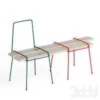
bench with rods
...bench with rods
3ddd
скамейка
bench with rods
3ddd
$1

диван ROD
...диван rod
3ddd
rod , living divani
http://www.livingdivani.it/
3ddd
$1

кресло ROD
...кресло rod
3ddd
rod , living divani
http://www.livingdivani.it/
design_connected
$18

Rod Armchair
...rod armchair
designconnected
living divani rod armchair computer generated 3d model. designed by lissoni, piero.
archive3d
free

Rod 3D Model
...rod 3d model
archive3d
shank rod
so rod - 3d model (*.gsm+*.3ds) for interior 3d visualization.
turbosquid
$15

Fishing rod
...urbosquid
royalty free 3d model fishing rod for download as on turbosquid: 3d models for games, architecture, videos. (1684756)
archive3d
free

Spinning rod 3D Model
...d spinning rod fishing-rod
spinning rod - 3d model (*.gsm+*.3ds) for interior 3d visualization.
Z
3d_export
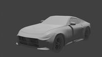
$5
nissan z
...nissan z
3dexport
nissan z
3ddd
$1

Vase Z
...vase z
3ddd
vase z
3ddd
$1
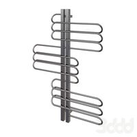
полотенцесушить Z
...полотенцесушить z
3ddd
полотенцесушитель
полотенцесушить z
design_connected
free

Z-Chair
...z-chair
designconnected
free 3d model of z-chair designed by karman, aleksei.
design_connected
$11

Z Lamp
...z lamp
designconnected
phillips z lamp computer generated 3d model. designed by kalff, louis.
3d_export
$5
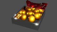
Dragon balls z
...dragon balls z
3dexport
dragon ball z
turbosquid
$20

Fighter Z
...
turbosquid
royalty free 3d model fighter z for download as on turbosquid: 3d models for games, architecture, videos. (1292563)
turbosquid
$9

Pen Z
...pen z
turbosquid
free 3d model pen z for download as obj on turbosquid: 3d models for games, architecture, videos. (1686775)
turbosquid
free
z chair
...z chair
turbosquid
free 3d model z chair for download as max on turbosquid: 3d models for games, architecture, videos. (1410230)
turbosquid
$5

Letter Z
...urbosquid
royalty free 3d model letter z for download as max on turbosquid: 3d models for games, architecture, videos. (1408540)
Parts
3d_export
$5
Parts
...parts
3dexport
parts
3d_export
$5
Part
...part
3dexport
part
3d_export
$5

Part
...part
3dexport
machine part
3d_export
$65

Part
...part
3dexport
simple rendering of the scene file
3d_export
$65

Part
...part
3dexport
simple rendering of the scene file
3d_export
$30

fan part
...fan part
3dexport
this is a part of fan of pedastal
3d_export
$10
machine parts
...machine parts
3dexport
3d part modeling work ,contact for 3d work
turbosquid
$59

Mechanical Part
...id
royalty free 3d model mechanical part for download as c4d on turbosquid: 3d models for games, architecture, videos. (1410833)
turbosquid
$17
Road parts
...bosquid
royalty free 3d model road parts for download as 3ds on turbosquid: 3d models for games, architecture, videos. (1192967)
turbosquid
$9

Cutter Parts
...squid
royalty free 3d model cutter parts for download as stl on turbosquid: 3d models for games, architecture, videos. (1220010)
2
design_connected
$11
No 2
...no 2
designconnected
sibast no 2 computer generated 3d model. designed by sibast, helge.
turbosquid
$6
Cliff Rock 2-2
...uid
royalty free 3d model cliff rock 2-2 for download as obj on turbosquid: 3d models for games, architecture, videos. (1619161)
turbosquid
$29

Book variation 2 2
...3d model book variation 2 2 for download as max, obj, and fbx on turbosquid: 3d models for games, architecture, videos. (1366868)
turbosquid
$22

Classic baluster (2) (2)
...assic baluster (2) (2) for download as max, obj, fbx, and stl on turbosquid: 3d models for games, architecture, videos. (1483789)
turbosquid
$99

Smilodon 2 Pose 2
... available on turbo squid, the world's leading provider of digital 3d models for visualization, films, television, and games.
turbosquid
$20

Barrel Barricade 2-2
... available on turbo squid, the world's leading provider of digital 3d models for visualization, films, television, and games.
turbosquid
$6

Wall Trophy (2) (2)
... available on turbo squid, the world's leading provider of digital 3d models for visualization, films, television, and games.
turbosquid
free
Tire label 2 of 2
... available on turbo squid, the world's leading provider of digital 3d models for visualization, films, television, and games.
3ddd
$1

Кровать, 2 тумбочки, 2 светильника
...кровать, 2 тумбочки, 2 светильника
3ddd
кровать, 2 тумбочки, 2 светильника
нормальное качество
формат 3ds max
без текстур
3ddd
free

Кровать, 2 тумбочки, 2 светильника
...кровать, 2 тумбочки, 2 светильника
3ddd
кровать, 2 тумбочки, 2 светильника
нормальное качество
формат 3ds max
без текстур