Thingiverse
Tesla coil using simple Slayer exciter by Lodestone
by Thingiverse
Last crawled date: 3 years ago
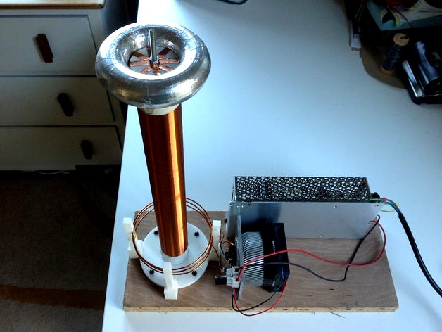
I blame the neighbour he said "how about building a Tesla coil" l have to admit I had thought about it in the past but the gauntlet was thrown.
This is the simplest method I could find being a single transistor oscillator which is basically a tank oscillator but with the tuned or resonant circuit attached to the base of the transistor. The other thing is that the secondary is only attached physically at one end the other end (top load end) is connected via capacitive coupling which is essentially what this divice demonstrates so well.
Tuning is a real issue with Tesla coils (usually ) but this desighn only has a tuned secondary which dictates what frequency the oscillator works at. This makes the thing self tuning.
Having said that it is a simple circuit it is very capable and if you are not careful you can easily get a nasty burn.
This device can also damage electronic devices if you have a pacemaker or any other medical equipment don't use this thing.
I can not accept responsibility for any stupid action you decide to take with this so please for your sake exercise some common sense. You will also be producing some Radio freqency interference in the medium wave yes I know what's that.
This is more powerful than most Slayer circuits you will see by virtue of the transistor I have used. Don't get me wrong a 2N3055 is a wonderful old device which I have used for more than 40 years but it is a bit out of its depth here. The real star here is the transistor I spent some time looking at specifications before choosing this one. Yes it is a grunt at 180 watts but the important point is it has allot of gain at the freqency we are using according to the spec there are two grades I have only seen the O grade on sale which has a minimum dc gain of 80 and a FT of 30 MHz so it should work well at 1Mhz.
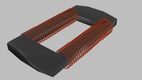
Base unit / Primary coil, place the coil supports into the Base in order 1,2,3,4 or 4,3,2,1 this will dictate if you wind clockwise or anti. It is important how the coils are connected my circuit diagram shows an S to indicate the start if both coils are wound the same way. You may need to sand the ends of the supports first. If you get stuck heat the offending part with boiling water then snug them down.
The coil wire can be straightened by holding one end in a vice and applying some stretching force take care don't end up on your back .Pre-form the 3 turn coil around a 100mm former a bit of old drain pipe will do. Place the coil in the former slots and glue with Araldite.
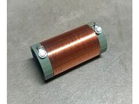
The secondary (tuned circuit ) was wound by hand tape the wire 25mm up from the end and wind up to 25mm before the end this will give near to 1000 turns. My tip here is to glue the coil with super glue at regular points and take breaks to avoid a horrible mess.
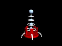
The top load holder has some supports to help with the printing snap them off and clean the part up with sandpaper. place the copper strip over the component as the picture and fit the 4mm screw ensure the holder fits snug on the end and solder the wire to it. Clean the enameled wire with sandpaper before soldering.
The top load (capacitive load), I filled the two halves with plasticine (putty or something similar) to give the top load weight. Glue the halves with super glue and give the doughnut a good sand to make it smooth. Clean and Apply strips (20mm ish) of Aluminium ducting tape to cover the whole item. I smooth all the wrinkles out with my thumb nail to make a very passable finish.
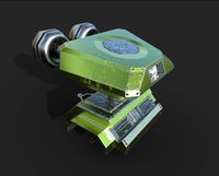
The exciter circuit, I have used a CPU cooling fan and heat sink I drilled 3 X 2.5mm and tapped them with a 3mm tap. This made life simple as I could screw the terminal block, transistor and regulator directly to the heat sink. Drilling all the way through and putting a nut on the other side is an option as too is using a large heat sink and no fan. DON'T skimp on the heat sink as half the power you put in will end up here as heat. The transistor requires an isolation pad but not the regulator as the tab needs to connect to 0v. I have made two ground connections to the heat sink. If you are looking for a ready supply of parts a tip here is look to that old PC you are storing the PSU alone will have useful hardware like heat sinks and fans also isolation kit.
Earthing is required I have been lazy and used the mains earth connecting it to the -Ve or 0V side of the PSU radiator or water pipe connection or even an earth rod should be considered.
Psu's, I had used my bench supply when I was experimenting but this cheap 24v 5A unit is so cheap and so readily available it was perfect I have turned it up to 27.5 which is the max I can get.
If you cannot get the exciter to oscillate the most likely cause will be the orientation of the coils we need to archive a 180 degree phase shift for oscillation to occurs. I would suggest reversing the connections on the primary if you have eliminated other mistakes.
Power mad ! although I'm pleased with the results I'm sure the I will be using the coil components to make a more powerful version I have allowed for more coils on the base unit as you can see.
You may have allot of fun exceeding the performance of what I have suggested yourself but I offer this as a good starting point.
This is the simplest method I could find being a single transistor oscillator which is basically a tank oscillator but with the tuned or resonant circuit attached to the base of the transistor. The other thing is that the secondary is only attached physically at one end the other end (top load end) is connected via capacitive coupling which is essentially what this divice demonstrates so well.
Tuning is a real issue with Tesla coils (usually ) but this desighn only has a tuned secondary which dictates what frequency the oscillator works at. This makes the thing self tuning.
Having said that it is a simple circuit it is very capable and if you are not careful you can easily get a nasty burn.
This device can also damage electronic devices if you have a pacemaker or any other medical equipment don't use this thing.
I can not accept responsibility for any stupid action you decide to take with this so please for your sake exercise some common sense. You will also be producing some Radio freqency interference in the medium wave yes I know what's that.
This is more powerful than most Slayer circuits you will see by virtue of the transistor I have used. Don't get me wrong a 2N3055 is a wonderful old device which I have used for more than 40 years but it is a bit out of its depth here. The real star here is the transistor I spent some time looking at specifications before choosing this one. Yes it is a grunt at 180 watts but the important point is it has allot of gain at the freqency we are using according to the spec there are two grades I have only seen the O grade on sale which has a minimum dc gain of 80 and a FT of 30 MHz so it should work well at 1Mhz.
Base unit / Primary coil, place the coil supports into the Base in order 1,2,3,4 or 4,3,2,1 this will dictate if you wind clockwise or anti. It is important how the coils are connected my circuit diagram shows an S to indicate the start if both coils are wound the same way. You may need to sand the ends of the supports first. If you get stuck heat the offending part with boiling water then snug them down.
The coil wire can be straightened by holding one end in a vice and applying some stretching force take care don't end up on your back .Pre-form the 3 turn coil around a 100mm former a bit of old drain pipe will do. Place the coil in the former slots and glue with Araldite.
The secondary (tuned circuit ) was wound by hand tape the wire 25mm up from the end and wind up to 25mm before the end this will give near to 1000 turns. My tip here is to glue the coil with super glue at regular points and take breaks to avoid a horrible mess.
The top load holder has some supports to help with the printing snap them off and clean the part up with sandpaper. place the copper strip over the component as the picture and fit the 4mm screw ensure the holder fits snug on the end and solder the wire to it. Clean the enameled wire with sandpaper before soldering.
The top load (capacitive load), I filled the two halves with plasticine (putty or something similar) to give the top load weight. Glue the halves with super glue and give the doughnut a good sand to make it smooth. Clean and Apply strips (20mm ish) of Aluminium ducting tape to cover the whole item. I smooth all the wrinkles out with my thumb nail to make a very passable finish.
The exciter circuit, I have used a CPU cooling fan and heat sink I drilled 3 X 2.5mm and tapped them with a 3mm tap. This made life simple as I could screw the terminal block, transistor and regulator directly to the heat sink. Drilling all the way through and putting a nut on the other side is an option as too is using a large heat sink and no fan. DON'T skimp on the heat sink as half the power you put in will end up here as heat. The transistor requires an isolation pad but not the regulator as the tab needs to connect to 0v. I have made two ground connections to the heat sink. If you are looking for a ready supply of parts a tip here is look to that old PC you are storing the PSU alone will have useful hardware like heat sinks and fans also isolation kit.
Earthing is required I have been lazy and used the mains earth connecting it to the -Ve or 0V side of the PSU radiator or water pipe connection or even an earth rod should be considered.
Psu's, I had used my bench supply when I was experimenting but this cheap 24v 5A unit is so cheap and so readily available it was perfect I have turned it up to 27.5 which is the max I can get.
If you cannot get the exciter to oscillate the most likely cause will be the orientation of the coils we need to archive a 180 degree phase shift for oscillation to occurs. I would suggest reversing the connections on the primary if you have eliminated other mistakes.
Power mad ! although I'm pleased with the results I'm sure the I will be using the coil components to make a more powerful version I have allowed for more coils on the base unit as you can see.
You may have allot of fun exceeding the performance of what I have suggested yourself but I offer this as a good starting point.
Similar models
thingiverse
free

Slayer Exciter - Telsa Coil 1.2Kv
...lpful: https://youtu.be/zewh_op2cnk
some specs:
primary coil: 3.5 turns
secondary coil: 12 turns
output: 12000v 4ma
weight: 150gr
3dwarehouse
free

Arrangement of Tesla
...a coils are often used by hobbyists and at venues such as science museums to produce long sparks. #gun #tesla #tesla_coil #weapon
thingiverse
free

Mini Tesla Coil Base by rogbigras
...y half way up the coil, it's where i got max feedback and and highest junction voltage. i'll make a youtube video one day
thingiverse
free

Tesla Coil Parts by Gmur
...l parts. you can use whatever you want
also included is a rod base which fits a coat hanger wire
used hot glue to stick together.
thingiverse
free

Small Musical Solid State Tesla Coil by Minkix
...and thermal paste.
additionally i covered the inside of the case with aluminum tape to protect the electronics from interference.
thingiverse
free

Tesla Coil Winder by laptopdr
...r it.
can be 3d printed with pla+.
you'll also need a stand for the magnet wire spool, which i might upload separately later.
thingiverse
free

Tesla Coil Primary Former by laptopdr
...e sku #1000050266.
3d printed in pla+ but nylon would be better since pla can break when you wind stiff 15 ga. magnet wire on it.
thingiverse
free
110uH Loading Coil Form for Short EFHW Antenna by Chetmystery
...terminals and 4mm bolts/hardware. second 4.5mm hole on each end can be used to loop antenna wire through to allow strain relief.
thingiverse
free

TC 110mm Primar conical support
...ou must glue it support holder.
for primary i use 6mm copper tube and for grounding 8mm copper tube.
this wersion is for 7 turns.
3dwarehouse
free

Tesla Magnifyer
...rdencliff tower. #coil #cylindrical #flat #longitudinal #magnifyer #pancake #radio #solenoid #spark_gap #tesla #transverse #waves
Lodestone
thingiverse
free

Queen Marking press-in-cage by Lodestone
...of the old super glue.
and there you have it a press in cage made from stuff you have quicker than ordering or going to the shop.
thingiverse
free

All year round Solar garden light by Lodestone
...e and you have issues.
ps
the funny l shape on the large square panel is an insulator as one tabbing strip passes over the other.
3dwarehouse
free

Lodestone Trench Grate
...lodestone trench grate
3dwarehouse
3dwarehouse
free

Building in Elk Grove, CA 95624, USA
...building in elk grove, ca 95624, usa 3dwarehouse lodestone ...
3dwarehouse
free

Building in Elk Grove, CA 95624, USA
...building in elk grove, ca 95624, usa 3dwarehouse lodestone ...
Slayer
turbosquid
$60

Barbarian Slayer
...d
royalty free 3d model barbarian slayer for download as fbx on turbosquid: 3d models for games, architecture, videos. (1210798)
turbosquid
$23

Titan Slayer
...alty free 3d model titan slayer for download as obj and blend on turbosquid: 3d models for games, architecture, videos. (1285640)
turbosquid
free
Slayer Sword
... available on turbo squid, the world's leading provider of digital 3d models for visualization, films, television, and games.
cg_studio
$20

Vampire Slayer Rigged3d model
...ed3d model
cgstudio
.lwo .lws - vampire slayer rigged 3d model, royalty free license available, instant download after purchase.
3d_export
$5

Dragon Slayer Sword
...dragon slayer sword
3dexport
3d model dragonslayer sword from anime berserk
3d_export
$10

tengu mask - urokodaki - demon slayer
...ask - urokodaki - demon slayer
3dexport
tengu mask from the anime demon slayer, ready for 3d printing or for use in 3d projects.
turbosquid
$6

Lamar - Slayer Swoard - Board
... available on turbo squid, the world's leading provider of digital 3d models for visualization, films, television, and games.
turbosquid
$39

The Slayer at Moonlight
...ty free 3d model la tueuse au claire de lune for download as on turbosquid: 3d models for games, architecture, videos. (1478966)
turbosquid
$10

Low-Poly Dagger Angel Slayer
...ree 3d model dagger angel slayer for download as obj and fbx on turbosquid: 3d models for games, architecture, videos. (1643289)
3d_export
$10

dragon slayer
...slayer
3dexport
sword of guts<br>metal steeelscratched<br>metal painted<br>metal medieval<br>wood worn 3
Exciter
3d_export
$5

demon of excitement
...demon of excitement
3dexport
demon of excitement
3ddd
$1

excite+ vario
...excite+ vario
3ddd
тренажер
элипсоид
turbosquid
$10

Toshiba Excite 10 SE
... available on turbo squid, the world's leading provider of digital 3d models for visualization, films, television, and games.
3ddd
$1

Туалетная вода AXE EXCITE
...парфюм
eau de toilette(туалетная вода) axe excite. polys:28670.файл с расширением mat открыть в material editor.(для формата fbx)
cg_studio
$2

Rim - AEZ Excite Dark3d model
...te dark3d model
cgstudio
.obj - rim - aez excite dark 3d model, royalty free license available, instant download after purchase.
3d_export
$40

Yamaha Exciter 3D model 3D Model
...yamaha exciter 3d model 3d model
3dexport
yamaha exciter 3d model 3d model fiv3 45041 3dexport
turbosquid
$59

Motion Trainer Excite + Vario Technogym
... available on turbo squid, the world's leading provider of digital 3d models for visualization, films, television, and games.
3d_export
$19

Full set of vibrating screen exciter
...g, eccentric shaft drawing, balance wheel drawing, shaft cover flange drawing, etc. 30 drawings, welcome to download and produce!
3d_ocean
$7

Axe Excite Perfume Bottle
...d has 38k polygon count. textures are created through uvw mapping method, and also been applied in same way, this file include...
3d_export
$10

Pole dance stage
...pole dance stage
3dexport
exciting red pole dance stage
Tesla
3d_export
$15

tesla cybertruck
...tesla cybertruck
3dexport
this is an tesla cybertruck.
3d_export
$5

Tesla emblem
...tesla emblem
3dexport
this is tesla emblem
3d_export
$5

nikola tesla
...nikola tesla
3dexport
nikola tesla
turbosquid
$15

Tesla - Rims - Tesla Model 3
...e 3d model tesla - rims - tesla model 3 for download as blend on turbosquid: 3d models for games, architecture, videos. (1612048)
3d_export
$5

Tesla coil
...tesla coil
3dexport
detailed tesla coil model
3d_export
$5

tesla cybertruck
...tesla cybertruck
3dexport
3d model of low poly tesla cybertruck
3d_export
$20

tesla cybertruck and tuning tesla cybertruck
...tesla cybertruck and tuning tesla cybertruck
3dexport
the model consists of 230 details
3d_export
$5

tesla cup
...;br>this file contains a model of a cup with the tesla logo.<br>made in the visualization and modeling program cinema 4d
3d_export
$15
tesla tower object
...tesla tower object
3dexport
tesla tower object
3d_export
$60

tesla cybertruck
...tesla cybertruck
3dexport
3d model tesla cybertruck hi-poly , corona render ,3ds max , obj , fbx
Coil
3d_export
$5
Tesla coil
...tesla coil
3dexport
detailed tesla coil model
archibase_planet
free

Fan coil
...fan coil unit air conditioning daikin conditioner
fan coil daikin n160915 - 3d model (*.gsm+*.3ds) for exterior 3d visualization.
cg_studio
$20

Coiled Rope3d model
...pe lasso coil bustermk2 coiled cord
.max - coiled rope 3d model, royalty free license available, instant download after purchase.
turbosquid
$8

Tesla Coil
...bosquid
royalty free 3d model tesla coil for download as fbx on turbosquid: 3d models for games, architecture, videos. (1458990)
turbosquid
$2

electronic coil
...y free 3d model electronic coil for download as obj and blend on turbosquid: 3d models for games, architecture, videos. (1503485)
turbosquid
$2
ferrite coil
...alty free 3d model ferrite coil for download as blend and obj on turbosquid: 3d models for games, architecture, videos. (1588248)
turbosquid
$15
Tesla Coil
... available on turbo squid, the world's leading provider of digital 3d models for visualization, films, television, and games.
turbosquid
$10

coil gun
... available on turbo squid, the world's leading provider of digital 3d models for visualization, films, television, and games.
turbosquid
$4

The transition coil
... available on turbo squid, the world's leading provider of digital 3d models for visualization, films, television, and games.
turbosquid
$19

Wooden coil
... wooden coil for download as max, 3ds, dae, dwg, fbx, and obj on turbosquid: 3d models for games, architecture, videos. (1656578)
Simple
turbosquid
$1

Simple goblet (Taca simples)
... available on turbo squid, the world's leading provider of digital 3d models for visualization, films, television, and games.
3d_export
$5
simple bench
...simple bench
3dexport
the simple bench which can be used in simple projects or video-games.
3d_export
$5
simple knob
...simple knob
3dexport
simple knob
3d_export
$5
simple handle
...simple handle
3dexport
simple handle
3d_export
$5
simple button
...simple button
3dexport
simple button
3d_export
$5
simple spindle
...simple spindle
3dexport
simple spindle
3d_export
$5

simple wheel
...simple wheel
3dexport
simple wheel
3d_export
$5

simple chair
...simple chair
3dexport
simple blue chair
3d_export
free

Simple room
...simple room
3dexport
here is a simple but beautiful room
3ddd
free

SIMPLE | Кресло
...io cianfarra , simple
производитель area declic дизайн giulio cianfarra коллекция simple
Using
3ddd
$1

US flag
...us flag
3ddd
флаг
us flag
3d_export
free

Among us
...among us
3dexport
among us red
3d_export
free

Among Us
...among us
3dexport
this 3d-model of a character from the game "among us". it can be used as a toy or decoration.
3d_export
$6

among us
...among us
3dexport
doll from among us in red
3d_export
$5

amoung us
...amoung us
3dexport
amoung us character. was created by cinema 4d 19
3d_export
$5
Humvee us
...humvee us
3dexport
humvee us 3d model good quality for animation
3d_export
$15

among us
...among us
3dexport
turbosmooth modifier can be used to increase mesh resolution if necessary
3d_export
$25

mailbox us
...mailbox us
3dexport
low poly model mailbox us. modeling in the blender, texturing in substance painter
design_connected
$13
Use Me
...use me
designconnected
sitland use me computer generated 3d model. designed by paolo scagnellato.
3d_export
$5

Among Us
...rt
the among us model comes in a variety of colors that can be customized by anyone, and even works with little in the animation