Thingiverse
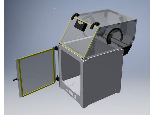
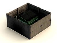
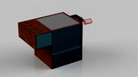
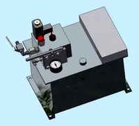
Temp Controlled Build Enclosure for UM2 by owen
by Thingiverse
Last crawled date: 3 years ago
Parts
1200 X 600 X 3mm Sheet (PVC, Acrylic etc.)
12V 40mm Fan
12V Power Supply
Chassis socket (to suit 12V Power Supply plug)
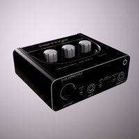
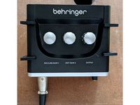
temperature controller on ebay http://www.ebay.com/itm/9-C-99-C-DC-12V-Intelligent-Digital-Led-Thermostat-Temperature-Controller-/321723841989
Clear Drying Glue
5 metres 6mm X 9mm white door seal strip
Clear Packaging tape
Masking Tape or similar
4 - 20mm X 4mm Screws
67 - 10mm X 3mm Screws
9 - 16mm X 3mm Screws
3 - 25mm X 3mm Screws
9 – 3mm nylock nuts
3mm washers
2 magnets to hold door one needs to be thin.
Instructions
Download Pictures for Instructions zip file and STLs zip file from http://www.thingiverse.com/thing:2137342/#files
I printed all parts in ABS with 2mm walls and thicker for hinges
Cut out panels from sheet to nearest mm
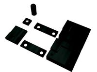
Print joiners, all front door parts, door frame mounts and joiner first
Mount front door hinges by replacing current UM screw with a 16mm screw on each one
Use a 16mm Screw for the front door handle.
Glue a thin magnet to the back of the door handle and tape a magnet behind the UM front panel.
Use masking tape to hold panels together making sure that the top panel sits between the left and right panel and not on top of them
Mark holes and drill panels making sure Joiner L4 is positioned in the gap of the cable ducts
Mount joiners and door frame mounts with 10mm screws on panels
Use clear packaging tape to join and seal panels where desired
Glue Top Door frame to joiners right way up and don’t use screws
Put Door seal on the Top door frame
Tape top door in place with masking tape and use the Top Hinges Template to mark mounting holes for the hinges.
Use 6 X 16mm screws for the Top Body Hinges
Mount Left handle with 3 X 25mm screws and Nyloc Nuts
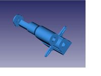
Thread thermocouple through the Thermocouple holder and attach it to the 25mm Left handle mounting bolts with nyloc nuts.
Push thermocouple far enough onto its holder so that the print head will miss it in the fully left position
Mount right handle with 10mm screws and nyloc nuts
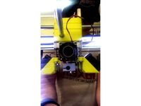
Mount the 40mm fan to the fan shroud using 4mm screws
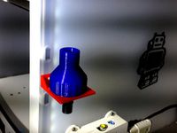
If printing in ABS use enclosure as is to print tall parts like the Bowden grommets
Ground wire goes from the Power Socket to the -DC terminal on the Temperature Controller and the Black wire on the fan.
12V positive from power socket goes to the +DC terminal on the Temperature Controller and to one side of the relay contacts.
The other side of the relay contacts goes to the red wire of the fan.
Glue the cable ducts in place
Duct Lid slides in position from underneath
Un-attach the Bowden cable(s)
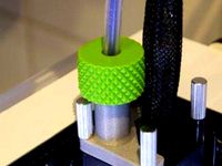
Mount the Right Bowden grommets flush with the outside panel of the UM then the left flush with the outside of the UM and with the print head cables passing through the slot.
Join the grommets together with the 2 X 10mm screws there will probably be a gap between them
Set start temp at the desired temperature and stop temperature to 1 degree above that. (Picture shows set at 45 degrees with current temp at 25 degrees.
1200 X 600 X 3mm Sheet (PVC, Acrylic etc.)
12V 40mm Fan
12V Power Supply
Chassis socket (to suit 12V Power Supply plug)
temperature controller on ebay http://www.ebay.com/itm/9-C-99-C-DC-12V-Intelligent-Digital-Led-Thermostat-Temperature-Controller-/321723841989
Clear Drying Glue
5 metres 6mm X 9mm white door seal strip
Clear Packaging tape
Masking Tape or similar
4 - 20mm X 4mm Screws
67 - 10mm X 3mm Screws
9 - 16mm X 3mm Screws
3 - 25mm X 3mm Screws
9 – 3mm nylock nuts
3mm washers
2 magnets to hold door one needs to be thin.
Instructions
Download Pictures for Instructions zip file and STLs zip file from http://www.thingiverse.com/thing:2137342/#files
I printed all parts in ABS with 2mm walls and thicker for hinges
Cut out panels from sheet to nearest mm
Print joiners, all front door parts, door frame mounts and joiner first
Mount front door hinges by replacing current UM screw with a 16mm screw on each one
Use a 16mm Screw for the front door handle.
Glue a thin magnet to the back of the door handle and tape a magnet behind the UM front panel.
Use masking tape to hold panels together making sure that the top panel sits between the left and right panel and not on top of them
Mark holes and drill panels making sure Joiner L4 is positioned in the gap of the cable ducts
Mount joiners and door frame mounts with 10mm screws on panels
Use clear packaging tape to join and seal panels where desired
Glue Top Door frame to joiners right way up and don’t use screws
Put Door seal on the Top door frame
Tape top door in place with masking tape and use the Top Hinges Template to mark mounting holes for the hinges.
Use 6 X 16mm screws for the Top Body Hinges
Mount Left handle with 3 X 25mm screws and Nyloc Nuts
Thread thermocouple through the Thermocouple holder and attach it to the 25mm Left handle mounting bolts with nyloc nuts.
Push thermocouple far enough onto its holder so that the print head will miss it in the fully left position
Mount right handle with 10mm screws and nyloc nuts
Mount the 40mm fan to the fan shroud using 4mm screws
If printing in ABS use enclosure as is to print tall parts like the Bowden grommets
Ground wire goes from the Power Socket to the -DC terminal on the Temperature Controller and the Black wire on the fan.
12V positive from power socket goes to the +DC terminal on the Temperature Controller and to one side of the relay contacts.
The other side of the relay contacts goes to the red wire of the fan.
Glue the cable ducts in place
Duct Lid slides in position from underneath
Un-attach the Bowden cable(s)
Mount the Right Bowden grommets flush with the outside panel of the UM then the left flush with the outside of the UM and with the print head cables passing through the slot.
Join the grommets together with the 2 X 10mm screws there will probably be a gap between them
Set start temp at the desired temperature and stop temperature to 1 degree above that. (Picture shows set at 45 degrees with current temp at 25 degrees.
Similar models
thingiverse
free
Wall-E Head-center mod by rene1960
...39;t have to glue in to the hinge.
credits for my friend ben for the redesign of the head-center part and the solar charge panel.
thingiverse
free
Wanhao Duplicator 6 Front door hinge & knob by quickturn
...ouble-stick tape (1pcs for magnet holder and body)
310 x 245 x 3mm board (acrylic board, plastic board, plywood, cardboard, etc.)
thingiverse
free

LIFT OFF HINGE FOR 3030 EXTRUSION by Duke_S
...n place very securely (door, hinges, etc) and started the holes slightly with the drill, checked them and then finished drilling.
thingiverse
free

Door Hinge / Door Joint - Smaller One by kevinvanlieshout
...vinvanlieshout
thingiverse
to joint a door.
dimensions: 16mm, 36mm
screws: 2x 3mm
nail: 40mm x 2.2mm
new ideas for this part?
thingiverse
free

Enclosure (Case) for DC 12V Fan Temperature Speed Controler by oaba
...ntroller can be purchased here.https://www.aliexpress.com/item/1005001388901396.html?spm=a2g0s.9042311.0.0.625f4c4dkhu1rl
enjoy !
grabcad
free

Panel Mounted Digital Temperature Controller
...- for use with a j-type (fe-cuni) thermocouple, 240vac or 24vac, one single output 240v vac max 8a resistive load. panel mounted.
grabcad
free

W1209 DC 12V heat cool temp thermostat temperature control switch temperature controller thermometer thermo controller
...tch-temperature-controller-thermometer-thermo-controller/32519582116.html?spm=2114.10010208.1000016.1.dar5ky&isorigtitle=true
grabcad
free

CABLE GROMMET 3MM
...cable grommet 3mm
grabcad
cable grommet 3mm
thingiverse
free

Pegboard simple magnet mount
...gboard.
after printing you can glue magnets into printed part (for me it worked even without glueing).
magnets: 10mm x 10mm x 3mm
thingiverse
free

Three 3 way Joiner - 10mm ID 16mm OD by JamesKomodo
...e stuff.
the id (internal diameter) is 10mm - the hole where you put dowels.
the od (outside diameter) is 16mm - 3mm thick walls.
Um2
3d_export
$1
hehringer ym2 - sound card
...card 3dexport low poly sound card simillar to behringer um2 ...
thingiverse
free

UM2 panel to upgrade with chineese UM2+ feeder by Haldahir
...with chineese um2+ feeder by haldahir
thingiverse
this is a pannel to mount the feeder of the um2+ (chineese and cheap version).
thingiverse
free
Tool mount for UM2 by kurgil
...tool mount for um2 by kurgil
thingiverse
simple tool mount for my um2...
thingiverse
free

BLtouch bracket for UM2 dual nozzle
...bltouch bracket for um2 dual nozzle
thingiverse
bltouch bracket for um2 dual nozzle head.
thingiverse
free

Glue stick mount for UM2 by kurgil
...glue stick mount for um2 by kurgil
thingiverse
simple mount for a glue stick for my um2
thingiverse
free
Bowden clamp for UM2 by chris_cki
...bowden clamp for um2 by chris_cki
thingiverse
we adapted owen's bowden clamp to the um2. thanks owen for your nice solution.
thingiverse
free
UM2 simple direct extruder by jhn
...um2 simple direct extruder by jhn
thingiverse
директ для um2. тяжеловат, но на 40/50мм нормально.
thingiverse
free

UM2+ Spoolholder by Tollenz
...um2+ spoolholder by tollenz
thingiverse
for spooldiameter till 300mm, brightnes from 55mm -100mm
thingiverse
free
UM2 E3D Fan Mount by Mudaseem
...my e3d v6, so i chose to use the stock um2 fan.
it mounts to the screws just like the cooling fans.
thanks e3d for the files!
-mm
thingiverse
free
Behringer U-PHORIA UM2 Mount by windatica
...o interface. two of these are printed out and slipped onto the um2. wood screws can then be used to fasten the bracket to a wall.
Owen
design_connected
$18

Owens
...owens
designconnected
minotti owens computer generated 3d model. designed by dordoni, rodolfo.
design_connected
$27

Owen
...owen
designconnected
bonaldo owen computer generated 3d model. designed by vigano - studio, giuseppe.
3ddd
$1

minotti owens
...minotti owens
3ddd
minotti , owens
кресло "minotti", модель"owens".
design_connected
$18

Owens Armchair
...owens armchair
designconnected
minotti owens armchair computer generated 3d model. designed by dordoni, rodolfo.
3ddd
$1

Rick Owens stag bench
...rick owens stag bench
3ddd
rick owens , скамейка
rick owens stag bench
turbosquid
$5
Owen Gun
... available on turbo squid, the world's leading provider of digital 3d models for visualization, films, television, and games.
3ddd
$1
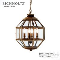
Eichholtz Lantern Owen
...60 cm
art.nr.: 108848
сайт:http://www.eichholtz.com/lantern-owen-0084012950114.aspx
форматы: max 2010, vax 2012, obj
turbosquid
$30

Owen Leather Armchair
...yalty free 3d model owen leather armchair for download as max on turbosquid: 3d models for games, architecture, videos. (1430311)
turbosquid
$18

Minotti Owens Armchair
...odel minotti owens armchair for download as max, obj, and fbx on turbosquid: 3d models for games, architecture, videos. (1391947)
3ddd
$1

RICK OWENS' stone chair
...
rick owens , каменный
stone chair by rick owens.
dimensions: 765x530x660 mm. polys:982
Temp
turbosquid
$10

Temp
... available on turbo squid, the world's leading provider of digital 3d models for visualization, films, television, and games.
design_connected
$4
Espace Temps
...espace temps
designconnected
ligne roset espace temps clocks computer generated 3d model. designed by martino d'esposito.
design_connected
$9

Temps Vecu Clock
...temps vecu clock
designconnected
ligne roset temps vecu clock computer generated 3d model. designed by tordjman, vincent.
turbosquid
$39

Temp 714 (Soviet TV set)
... available on turbo squid, the world's leading provider of digital 3d models for visualization, films, television, and games.
3d_export
$29
Tempe Round Metal Dining Table 3D Model
...al style
tempe round metal dining table 3d model download .c4d .max .obj .fbx .ma .lwo .3ds .3dm .stl radionovas1 108858 3dexport
3d_export
$199

tempe city arizona usa 20km
...der ready. 1. suitable for games, games, education, architecture etc. 2. mainly used for town and urban planning, real estate etc
3ddd
$1
SERIP2010 Diamond CT3295
...serip2010 diamond ct3295 3ddd serip http://www.serip.com.pt/temp ...
3d_export
$10
interior lamp
...use any standard hanging light cord and a low temp bulb (such as a cfl...
3d_export
$20
SMITHS gauge collection 3D Model
...gauge indicator cluster smiths car vehicle ammeter voltmeter water temp oil presure clock fuel rpm speed smiths gauge collection...
3ddd
free
Caracole Socialite
...3ddd caracole , social , журнальный кофейный столик размеры: 138x80x50hhttp://www.caracole.com/gallerydetails?id=439&ref;=gallery&viewall;=true&type;=whatsnew&zid;=3&temp=y ...
Enclosure
3d_export
free
electrical enclosure
...l enclosure where electrical devices like (relays, contactors, busbars ) are kept in order to protect from hazardous environment.
turbosquid
$100

GPU Enclosure
...yalty free 3d model gpu enclosure for download as obj and stl on turbosquid: 3d models for games, architecture, videos. (1381061)
3d_export
$5
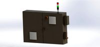
Electrical Enclosure
...ed. also has tower lights attaced on the top.<br>file format that are available:<br>.step<br>.obj<br>.stl
archive3d
free
Enclosure 3D Model
...closure 3d model
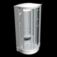
archive3d
shower enclosure-acquarius- 3d model for interior 3d visualization.
archive3d
free
Enclosure 3D Model
...enclosure 3d model
archive3d
shower enclosure-omega- 3d model for interior 3d visualization.
archive3d
free
Enclosure 3D Model
...enclosure 3d model
archive3d
shower enclosure-vega - 3d model for interior 3d visualization.
archive3d
free
Enclosure 3D Model
...enclosure 3d model
archive3d
shower enclosure-zenith - 3d model for interior 3d visualization.
turbosquid
$20
shower enclosure
... available on turbo squid, the world's leading provider of digital 3d models for visualization, films, television, and games.
turbosquid
$14
Dumpster Enclosure
... available on turbo squid, the world's leading provider of digital 3d models for visualization, films, television, and games.
turbosquid
$25
3d printer enclosure
... model 3d printer enclosure for download as ipt, skp, and fbx on turbosquid: 3d models for games, architecture, videos. (1634310)
Controlled
3d_ocean
$4
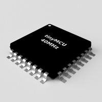
Controller TQFP32
...qfp32
3docean
chip controller cpu electronic gpu mcu micro controller silicon smd tqfp wafer
a micro controller in tqfp32 package
3d_ocean
$4
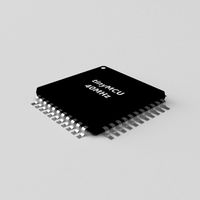
Controller TQFP44
...44
3docean
chip controller cpu electronic gpu mcu micro controller package smd tqfp tqfp44
a micro controller in a tqfp44 package
3d_export
$15
control unit
...control unit
3dexport
control unit
3ddd
$1
Yacht control
...yacht control
3ddd
yacht control
3d_export
$5
controle pgdm
...controle pgdm
3dexport
carcaca controle pgdm
turbosquid
free
controler
... available on turbo squid, the world's leading provider of digital 3d models for visualization, films, television, and games.
3ddd
$1

Control
...
http://www.schmitz-leuchten.de/html-ru/einzelleuchten-lampentyp-details.php?lamptype_no=700&group;=917&id;=731
3d_ocean
$4
Controller TQFP100
...100
3docean
chip computer cpu electronic gpu mcu micro controller pin platine silicon wafer
a micro controller in tqfp100 package
3d_ocean
$4
Controller TQFP64
...qfp64
3docean
chip computer cpu gpu mcu micro controller package silicon tqfp tqfp64 wafer
a micro controller in a tqfp64 package
3d_ocean
$7

Remote controller
... control switcher tv remote
remote controller for tv, sound systems etc easy to edit textures photo real rendered with mental ray
Build
archibase_planet
free
Building
...building high-rise building office building construction
building n050115 - 3d model (*.gsm+*.3ds) for exterior 3d visualization.
3d_export
$5
building
...building
3dexport
clasic building
3ddd
$1
building
...building
3ddd
здание
building
archibase_planet
free
Building
...lanet
building office office building construction
building n090914 - 3d model (*.gsm+*.3ds+*.max) for exterior 3d visualization.
archibase_planet
free
Building
...net
building tower construction high-rise building
building n100214 - 3d model (*.gsm+*.3ds+*.max) for exterior 3d visualization.
3d_export
free
Building
...building
3dexport
low poly building;
3d_export
free
Building
...building
3dexport
low poly building;
3d_export
free
Building
...building
3dexport
low poly building;
3d_export
free
Building
...building
3dexport
low poly building;
3d_export
free
Building
...building
3dexport
low poly building;