Thingiverse
t-trak command/control module set by JoshMurrah
by Thingiverse
Last crawled date: 3 years, 1 month ago
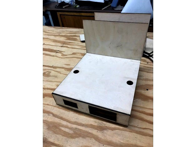
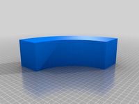
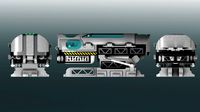
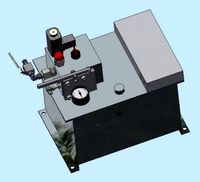
This is a pair of t-trak modules that provide command/control and power districts for a t-trak layout. The modules are designed to be back-to-back and the tracks be insulated in the middle with two sets of feeders, so you end up with four power districts with the command/control splitting things in the middle.
I had some goals in building this:
module format, easy to transport
sitting on table top as a conversation piece
providing rail power and east/west cables, module sits in the middle reducing bus lengths
create power districts to aid in troubleshooting
provide lots of visual status options, voltage/amperage in front, all status lights above-table
provide a base for a mast that has wireless options along with a decorative crossbuck/lights
components to use and notes:
front is designed to take a Digitrax UP5 or similar for throttles and a RRampMeter for voltage/amps display
left/right rear on top are designed for booster/command and circuit protection area (I'm using Digitrax DSC240 + BXP88)
two track main and programming track in front
skyboard is permenantly attached due to amount of holes in back, mount extras there (I'm mounting a Pi and USB router)
back has 2x 40mm fans for cooling, three power pole outlets for east/west power and 12V power and grommet for sister module pigtals and AC cord
mount 12v 20A power supply underneath, tuned to 14v, and whatever distro blocks you like to use
mount metal threaded pipe flange in center/top area for wireless/decorative mast
sister module needs the same double-feed track lines that are insulated in the middle to create power districts, there's three outlets on the back of the sister module that are for east/west power inputs plus 12V power input. I'll be using a double crossover which is mostly already gapped, with feeders added on the ends.
update 9/5/17 - uploaded a few pics of the cut parts test assembled.
update 10/11/2017 - assembling final product now... found that since I glue in large wood blocks for feet in the corners, the fan holes get covered, so I'm going to use the "sister" back instead on the power module and cut a fan hole in the top instead. These modules are also about 5mm too wide (they're the exact width of trackage) which I believe was a result of using a lower powered laser and making two passes, not cutting thick enough, or perhaps due to some of the graphics file conversions.
Similar models
thingiverse
free

DPH5005 Enclosure (customizable)
...pole connection for the output.
note: the lcd panel is a little tight. in goes in easy but it is a little tough getting back out.
thingiverse
free
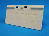
T-Trak Track Alignment Gauge by callmelightningjunior
.../ for example modules.
see http://ttrak.wikidot.com/hillside for an example of modules using the 3-position single track concept.
thingiverse
free

Power expansion module mount by pogoqc
... mount by pogoqc
thingiverse
mount for power module.
uses a 40mm fan.
mounting holes uses m5's .
module holes uses m3's.
thingiverse
free

PS2 120mm Fan Adapter by bcernic
...but with it being so silent, that is not a big deal.
required hardware:
1x 120mm pc fan (silent fan recommended)
8x pc fan screws
thingiverse
free

Fan mount for Prusa i3 motor controllers by abrokadabra
...r whatever size fan you have.
i simply melted the fan mount to this print, and wired the fan directly into my 12v power supply.
thingiverse
free

Control MOSFET module directly from Arduino output pin by Paran0ic
...ain sufficient current for optocoupler.
modified mosfet module works with 5v inputs and it is safe to control it with 12v inputs.
thingiverse
free
t-trak viaduct segment by JoshMurrah
...ded an alignment tool that should have the correct offset of the deck.
i used the stone stencil, thing 2059343 by myxerion
enjoy!
thingiverse
free
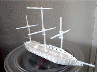
ship (battle) by jappieb
... full front-back 2x new
mast full middle part 1 1x new
mast full middle part 2 1x new
mast front 1x
mast nest 3x
mast back new 3x
thingiverse
free

LM2596 StepDown Mount by Andys1957
...nt by andys1957
thingiverse
mount for a lm2596 stepdown module i use in my ctc bizer to generate 12v for cooling fan and lights.
thingiverse
free

T-TRAK-Z module collection by JoshMurrah
...4s and chop them into 2" sections to make squarish blocks that i can drill and insert t-nuts and bolts into for feet.
enjoy!
Joshmurrah
thingiverse
free
t-trak viaduct segment by JoshMurrah
...ded an alignment tool that should have the correct offset of the deck.
i used the stone stencil, thing 2059343 by myxerion
enjoy!
thingiverse
free

foot spacer for folding card table by JoshMurrah
...rt of the thing is pretty low poly, it was a quickie in tinkercad.
i suggest adding some self-adhesive felt/rubber to the bottom.
thingiverse
free

t-trak R19 endcap inside area by JoshMurrah
...you a "covering" or flat style endcap, versus the outside corner style i posted where there would be a curved skyboard.
thingiverse
free

MKS GEN 1.4 mount split by JoshMurrah
... in the bed and save on plastic.
you'll need to import to your slicer and separate into the two parts and re-position.
enjoy!
thingiverse
free

Z scale wood grade crossing by JoshMurrah
...is with an anycubic photon, some detail was lost but there's still the impression of board lines, which is ok by me.
enjoy!
thingiverse
free

T-TRAK-Z alignment tool by JoshMurrah
...tion and screw/nail to secure.
some additional white or wood glue is also recommended along the edge, for security on the module.
thingiverse
free

n scale pasture fence by JoshMurrah
... easier.
i printed these on an anycubic photon with fairly good success, print time is very short since they're printed flat.
thingiverse
free

SQ11 N scale camera car by JoshMurrah
...ront and back edges back to bolster to get the edges out of frame, added bolster pins back into the design, and added truck info.
thingiverse
free
t-trak R12 viaduct corner by JoshMurrah
...strainer over a boiling pot and kept turning it over until it was soaked.
this is designed to take r282mm + r315mm kato unitrack.
thingiverse
free

tailgate hingepin for Peg Perego John Deere ride-on by JoshMurrah
...or two jammed nuts) for the back side, as well as drilling the center of the old hingpin area with a 7/64" drill bit.
enjoy!
Trak
turbosquid
$10

Suppressor Trak
...squid
royalty free 3d model suppressor trak for download as on turbosquid: 3d models for games, architecture, videos. (1395793)
turbosquid
$19

Trak ZIL 130
...d model trak zil 130 for download as obj, fbx, blend, and stl on turbosquid: 3d models for games, architecture, videos. (1174466)
thingiverse
free

Big Trak Front Axle by Gadgeteering
...big trak front axle by gadgeteering
thingiverse
replacement axle for big trak
thingiverse
free

FPV Tiny Trak by Ajaxjones
...erse
components to build a fpv tiny trak, also look at https://www.thingiverse.com/thing:2935413 which uses the same lego tracks
thingiverse
free

Flysky Trak
...g:4010666
the tracks i use: https://www.thingiverse.com/thing:2946698
the wheels i use: https://www.thingiverse.com/thing:3040499
thingiverse
free

Remix of the Tiny Trak Wheel Base
...
thingiverse
i use this remixed wheel base for my tiny traks. i removed the third wheel mount to add a pseudo suspension effect.
thingiverse
free

Stand for Tak trak baby monitor by RoeyPe
...rse
my design to baby camera stand tak trak.
i printes with the top of the model on the hot plate with supports for build plate
thingiverse
free

tiny trak no bearing track idler
...tiny trak no bearing track idler
thingiverse
remixed idler for use without bearings. recommend using nylock nut and washers
thingiverse
free

Tiny Trak - Print in Place Tread by BigOwnge
...tps://www.facebook.com/groups/181517579149618/
i have printed in pla and works great!
https://www.youtube.com/watch?v=snuvjmeu5ey
thingiverse
free
t-trak viaduct segment by JoshMurrah
...ded an alignment tool that should have the correct offset of the deck.
i used the stone stencil, thing 2059343 by myxerion
enjoy!
Command
turbosquid
$10
Commander
...
turbosquid
royalty free 3d model commander for download as on turbosquid: 3d models for games, architecture, videos. (1256307)
3d_export
$13

command knife
...command knife
3dexport
command knife
turbosquid
$10

Command
... available on turbo squid, the world's leading provider of digital 3d models for visualization, films, television, and games.
turbosquid
$140

Command vehicle A
...
royalty free 3d model command vehicle a for download as max on turbosquid: 3d models for games, architecture, videos. (1662822)
turbosquid
$60
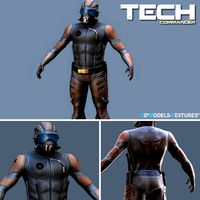
Tech Commander
...uid
royalty free 3d model tech commander for download as fbx on turbosquid: 3d models for games, architecture, videos. (1209942)
turbosquid
$49

Commander C40
...yalty free 3d model commander c40 for download as 3ds and 3dm on turbosquid: 3d models for games, architecture, videos. (1283262)
turbosquid
$9
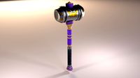
Commanding Mallet
...d model commanding mallet for download as obj, fbx, and blend on turbosquid: 3d models for games, architecture, videos. (1448575)
turbosquid
$100

command exc
... available on turbo squid, the world's leading provider of digital 3d models for visualization, films, television, and games.
turbosquid
$99

Command Vehicle
... available on turbo squid, the world's leading provider of digital 3d models for visualization, films, television, and games.
turbosquid
$40

ship commander
... available on turbo squid, the world's leading provider of digital 3d models for visualization, films, television, and games.
Module
turbosquid
$4

Module
...
turbosquid
royalty free 3d model module for download as max on turbosquid: 3d models for games, architecture, videos. (1259603)
3d_export
free

Martian module
...martian module
3dexport
martian module objects 18 textures are missing
design_connected
$39
Kennedee Moduls
...kennedee moduls
designconnected
kennedee moduls computer generated 3d model. designed by massaud, jean-marie.
design_connected
$39
Sayonara Moduls
...sayonara moduls
designconnected
bbb emmebonacina sayonara moduls computer generated 3d model. designed by decursu, giorgio.
design_connected
$27

Togo Moduls
...togo moduls
designconnected
ligne roset togo moduls computer generated 3d model. designed by ducaroy, michel.
design_connected
$34
Nuvola Moduls
...nuvola moduls
designconnected
bonaldo nuvola moduls 2-seater computer generated 3d model. designed by giuseppe viganò.
3d_export
free
Hibernation module
...hibernation module
3dexport
design_connected
$27
Sabi moduls
...sabi moduls
designconnected
paola lenti sabi moduls 2-seater computer generated 3d model. designed by francesco rota.
3d_export
$50

pls concrete module
...pls concrete module
3dexport
pls concrete module<br>pls with concrete mobile mixer module m5
turbosquid
free
Hibernation module
...squid
free 3d model hibernation module for download as blend on turbosquid: 3d models for games, architecture, videos. (1667696)
Control
3d_ocean
$4
Controller TQFP32
...qfp32
3docean
chip controller cpu electronic gpu mcu micro controller silicon smd tqfp wafer
a micro controller in tqfp32 package
3d_ocean
$4
Controller TQFP44
...44
3docean
chip controller cpu electronic gpu mcu micro controller package smd tqfp tqfp44
a micro controller in a tqfp44 package
3d_export
$15
control unit
...control unit
3dexport
control unit
3ddd
$1
Yacht control
...yacht control
3ddd
yacht control
3d_export
$5
controle pgdm
...controle pgdm
3dexport
carcaca controle pgdm
turbosquid
free
controler
... available on turbo squid, the world's leading provider of digital 3d models for visualization, films, television, and games.
3ddd
$1

Control
...
http://www.schmitz-leuchten.de/html-ru/einzelleuchten-lampentyp-details.php?lamptype_no=700&group;=917&id;=731
3d_ocean
$4
Controller TQFP100
...100
3docean
chip computer cpu electronic gpu mcu micro controller pin platine silicon wafer
a micro controller in tqfp100 package
3d_ocean
$4
Controller TQFP64
...qfp64
3docean
chip computer cpu gpu mcu micro controller package silicon tqfp tqfp64 wafer
a micro controller in a tqfp64 package
3d_ocean
$7

Remote controller
... control switcher tv remote
remote controller for tv, sound systems etc easy to edit textures photo real rendered with mental ray
Set
archibase_planet
free

Setting
...setting
archibase planet
setting cover place setting
setting - 3d model (*.gsm+*.3ds) for interior 3d visualization.
archibase_planet
free
Setting
...setting
archibase planet
setting place setting cover
setting - 3d model (*.gsm+*.3ds) for interior 3d visualization.
archibase_planet
free

Setting
...setting
archibase planet
setting place setting cover
setting - 3d model (*.gsm+*.3ds) for interior 3d visualization.
3d_export
$8

decorative set mens set
...decorative set mens set
3dexport
decorative set men's set
archibase_planet
free
Set
...anet
set kitchen ware kitchen set kitchen tools
set kitchen tools n281114 - 3d model (*.gsm+*.3ds) for interior 3d visualization.
archibase_planet
free
Set
...set
archibase planet
beer set bar equipment
beer set - 3d model for interior 3d visualization.
archibase_planet
free

Set
...set
archibase planet
cover place setting
set - 3d model (*.gsm+*.3ds) for interior 3d visualization.
archibase_planet
free

Set
...set
archibase planet
kitchen set kitchen ware
set - 3d model (*.gsm+*.3ds) for interior 3d visualization.
archibase_planet
free
Set
...set
archibase planet
set cup glass kitchen ware
set - 3d model (*.gsm+*.3ds) for interior 3d visualization.
archibase_planet
free

Set
...set
archibase planet
flatware cover place setting
set n311210 - 3d model (*.gsm+*.3ds) for interior 3d visualization.
T
design_connected
$11

T & T
...t & t
designconnected
dark t & t computer generated 3d model. designed by de ryck, christophe.
3d_export
$5

t-800
...t-800
3dexport
t-800
3ddd
$1
Table T
...table t
3ddd
журнальный
table t
3ddd
free
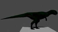
T-Rex
...t-rex
3ddd
t-rex
rrrrrr
3d_export
$5

t-virus
...t-virus
3dexport
it's t-virus
3d_export
$5

T-26T
...t-26t
3dexport
artillery tractor on the t-26 chassis ussr
3ddd
$1
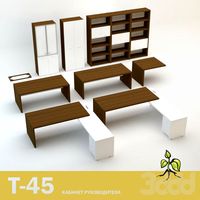
T 45
...t 45
3ddd
t-45
кабинет руководителя t 45
12 предметов
подробнее:http://www.prezident-mebel.ru/index.php?productid=1541
3ddd
free

SAFE T
...safe t
3ddd
огнетушитель
креативные огнетушители от компании safe t
3d_export
free
t-rex
...t-rex
3dexport
t-rex have normal map and base color textures
3d_export
$75
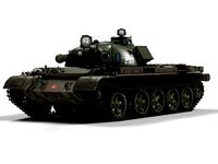
T-55
...nally, but these improvements made the tank more efficient and lethal. the t-55 was officially adopted by the soviet army in 1958