Thingiverse
Superlight SOTA Vertical for 40-30-20m with Loading Coil by mfhepp
by Thingiverse
Last crawled date: 3 years ago
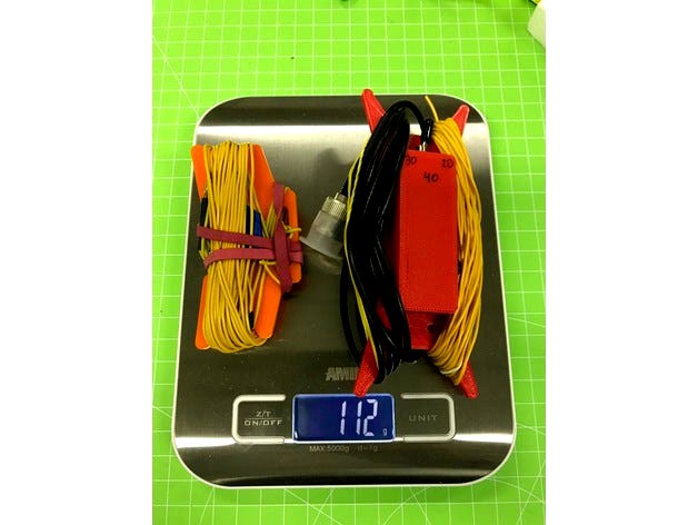
This is the enclosure and winder for a superlight, base loaded vertical antenna, mainly for SOTA operating. The antenna is ideal for use with a 6m fiber-glass or carbon-fiber mast.
It is a redesign of the approach of an antenna marketed by QRPguys and developed by Joe Everhart, N2CX: http://qrpguys.com/qrpguys-tri-band-portable-vertical-antenna.
My approach differs in the following ways from the original one:
I use one tapped coil on a singleT68-2 core instead of two coil in order to obtain the required inductances for 40 and 30 m (more details below).
Instead of two SPST slide switches, I use a single SPDT 3-pole on-off-on switch.
I added a common mode choke in order to reduce the effect of unavoidable asymmetries between the radiator and the counterpoise.
Instead of four 10 ft. ground radials, my design can also be used with
a) one elevated, resonant radial, tuned for each band by winding up the remaining wire, or
b) three elevated, resonant radials attached to each other.
Materials
1 Amidon T68-2 toroid
1 Amidon / FairRite FT50-43 toroid
1 SPDT Switch On-Off-On, e.g. MIYAMA MS-167 (Reichelt: MS 167)
Two pieces of 0.5 mm magnet wire, 100 cm and ca. 55 cm
ca. 20m of SOTA beams antenna wire (diameter ca. 0.5 mm, https://www.sotabeams.co.uk/antenna-wire-lightweight-100m/)
1 SOTAbeams Mini Wire Winder (https://www.sotabeams.co.uk/mini-wire-winders/). Instead of these, you can also use https://www.thingiverse.com/thing:1173824/ but scaled to 66% in the X and Y axis and 100% for the Z axis (3 mm high).
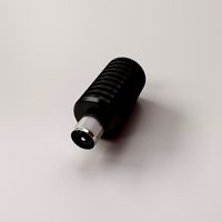
1 2mm plug Hirschmann 930308100 (Reichelt: MBI 1 SW)
1 gold-plated 2 mm connector (like those available for RC batteries, cf. ebay)
1 BNC connector for RG 174
1.6 m of RG 174
Various rubber cable grommets 3.4 - 5 mm inner diameter
Optional for sloped configuration from carbon-fiber masts:
1.8 m of polyester cord, e.g. SOTAbeams hi-viz antenna cord, https://www.sotabeams.co.uk/hi-viz-antenna-cord/
1 aluminium peg, like https://www.sotabeams.co.uk/aluminium-alloy-peg-price-per-one-peg/
Heat-shrink tube
Assembly
Cut the radiator to length; I recommend starting with 5.17 m plus 10 - 15 cm extra for tuning.
Prepare the common-mode choke: Twist 55 cm of 0.5. magnet wire tightly in order to obtain a 50 ohms impedance and wind 11 turns through the FT50-43 toroid.
Mount the BNC connector to the RG 174 cable and put it throuth the two 3 mm holes on the left legt of the enclosure as a strain relief (see picture).
Solder connect the other end of the RG 174 to the two ends of the common mode choke. At this point, polarity does not yet matter.
Use a continuity tester or ohmmeter to figure out which of the two open ends of the common-mode choke are connected to the ground shield of the RG 174. Mark that, e.g. with a black permanent pen.
Mount the black 2mm plug and the SPDT switch and solder the magnet wire marked in step 5 to this plug.
Put the end of the radiator wire through the 1.2 mm holes on the opposite leg of the enclosure (see picture).
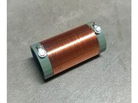
Prepare the loading coil: Take the 100 cm of 0.5. magnet wire and wind 25..26 turns, then add a short tap, then another 20..21 turns. Leave at least 10 cm on either end so that you can adjust the tap by adding a turn on one side and removing one on the other.
Now tune the loading coil with a component tester or other device for measuring inductances. The total coil should have 11.5 - 12 uH, the 25..26 turns should have 3.4 - 3.6 uH. It is important to shorten the rest of the coil (i.e. the 20..21 turns) while measuring the inductance of the lower 25..26 turns.
Now connect
a) the open end of the common-mode choke with the start of the loading coil
b) the tap of the loading coil with the left (or right) connector of the SPDT switch,
c) the end of the loading coil and the radiator wire with the middle connector of the SPDT switch, and
d) the start of the loading coil with the remaining connector of the SPDT switch.
You are all set, except for the radials / counterpoise. I recommend a single, resonant counterpoise, which gives greater efficiency but is a bit more difficult to tune. Solder the 2mm plug to one end and secure it with 3.2 mm heat-shrink tube. Tie the other end to the mini-winder in order to not loose it when throwing out the counterpoise from a mountain top. Wind up all wire.
The rubber cable grommets are attached to the end of the radiator wire and allow a flexible connection of the wire to the mast; this idea is from Heinz Baertschi, HB9BCB.
Tuning
Put the SPDT switch into the position in which it shortens the entire loading coil.
Attach the antenna to a 6m mast with an initial radiator length of 5.17 m. Fold back the extra radiator wire.
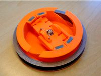
The enclosure/winder should be attached to the mast with two rubber bands, which will go cross-wise from the four legs of the winder. The enclouse should be ca. 75 - 80 cm above ground level.
Now tune the antenna to resonance by winding up the counterpoise. A good starting point is ca. 5 m. Make sure that the counterpoise is sloping down from the enclosure. In particular the first meters should not touch the ground. The height above ground of the end influences the tuning. Elevating the end ca. 60 cm gives better performance, but can be difficult in the field.
Mark the tuned length of the counterpoise, ideally with something you can feel in bad light, e.g. a knot of cord or rubbert band etc.
Now tune for 30 and 40 m accordingly.
You are all set!
When using with a carbon-fiber mast, the tuning may change, and it may be unstable if the wind changes the distance between mast and radiator. In this case, I recommend a steeply sloped configuration, i.e. holding the winder/enclosure ca. 1m away from the base of the mast. For this purpose, tie the hi-viz cord to the two unused holes in the enclosure, add a loop to the other end, and fix it with a peg. The antenna may require retuning for this configuration.
Acknowledgments
The antenna is inspired by the original design by Joe Everhart, N2CX. The idea to use a single SPDT on-off-on switch and the use of rubber cable grommets is from Heinz Baertschi, HB9BCB. The tiny common-mode choke is inspired by the "pico balun" from Richard Newstead, G3CWI, available via SOTAbeams (https://www.sotabeams.co.uk/pico-balun-1-1-or-4-1-balun-kit/).
It is a redesign of the approach of an antenna marketed by QRPguys and developed by Joe Everhart, N2CX: http://qrpguys.com/qrpguys-tri-band-portable-vertical-antenna.
My approach differs in the following ways from the original one:
I use one tapped coil on a singleT68-2 core instead of two coil in order to obtain the required inductances for 40 and 30 m (more details below).
Instead of two SPST slide switches, I use a single SPDT 3-pole on-off-on switch.
I added a common mode choke in order to reduce the effect of unavoidable asymmetries between the radiator and the counterpoise.
Instead of four 10 ft. ground radials, my design can also be used with
a) one elevated, resonant radial, tuned for each band by winding up the remaining wire, or
b) three elevated, resonant radials attached to each other.
Materials
1 Amidon T68-2 toroid
1 Amidon / FairRite FT50-43 toroid
1 SPDT Switch On-Off-On, e.g. MIYAMA MS-167 (Reichelt: MS 167)
Two pieces of 0.5 mm magnet wire, 100 cm and ca. 55 cm
ca. 20m of SOTA beams antenna wire (diameter ca. 0.5 mm, https://www.sotabeams.co.uk/antenna-wire-lightweight-100m/)
1 SOTAbeams Mini Wire Winder (https://www.sotabeams.co.uk/mini-wire-winders/). Instead of these, you can also use https://www.thingiverse.com/thing:1173824/ but scaled to 66% in the X and Y axis and 100% for the Z axis (3 mm high).
1 2mm plug Hirschmann 930308100 (Reichelt: MBI 1 SW)
1 gold-plated 2 mm connector (like those available for RC batteries, cf. ebay)
1 BNC connector for RG 174
1.6 m of RG 174
Various rubber cable grommets 3.4 - 5 mm inner diameter
Optional for sloped configuration from carbon-fiber masts:
1.8 m of polyester cord, e.g. SOTAbeams hi-viz antenna cord, https://www.sotabeams.co.uk/hi-viz-antenna-cord/
1 aluminium peg, like https://www.sotabeams.co.uk/aluminium-alloy-peg-price-per-one-peg/
Heat-shrink tube
Assembly
Cut the radiator to length; I recommend starting with 5.17 m plus 10 - 15 cm extra for tuning.
Prepare the common-mode choke: Twist 55 cm of 0.5. magnet wire tightly in order to obtain a 50 ohms impedance and wind 11 turns through the FT50-43 toroid.
Mount the BNC connector to the RG 174 cable and put it throuth the two 3 mm holes on the left legt of the enclosure as a strain relief (see picture).
Solder connect the other end of the RG 174 to the two ends of the common mode choke. At this point, polarity does not yet matter.
Use a continuity tester or ohmmeter to figure out which of the two open ends of the common-mode choke are connected to the ground shield of the RG 174. Mark that, e.g. with a black permanent pen.
Mount the black 2mm plug and the SPDT switch and solder the magnet wire marked in step 5 to this plug.
Put the end of the radiator wire through the 1.2 mm holes on the opposite leg of the enclosure (see picture).
Prepare the loading coil: Take the 100 cm of 0.5. magnet wire and wind 25..26 turns, then add a short tap, then another 20..21 turns. Leave at least 10 cm on either end so that you can adjust the tap by adding a turn on one side and removing one on the other.
Now tune the loading coil with a component tester or other device for measuring inductances. The total coil should have 11.5 - 12 uH, the 25..26 turns should have 3.4 - 3.6 uH. It is important to shorten the rest of the coil (i.e. the 20..21 turns) while measuring the inductance of the lower 25..26 turns.
Now connect
a) the open end of the common-mode choke with the start of the loading coil
b) the tap of the loading coil with the left (or right) connector of the SPDT switch,
c) the end of the loading coil and the radiator wire with the middle connector of the SPDT switch, and
d) the start of the loading coil with the remaining connector of the SPDT switch.
You are all set, except for the radials / counterpoise. I recommend a single, resonant counterpoise, which gives greater efficiency but is a bit more difficult to tune. Solder the 2mm plug to one end and secure it with 3.2 mm heat-shrink tube. Tie the other end to the mini-winder in order to not loose it when throwing out the counterpoise from a mountain top. Wind up all wire.
The rubber cable grommets are attached to the end of the radiator wire and allow a flexible connection of the wire to the mast; this idea is from Heinz Baertschi, HB9BCB.
Tuning
Put the SPDT switch into the position in which it shortens the entire loading coil.
Attach the antenna to a 6m mast with an initial radiator length of 5.17 m. Fold back the extra radiator wire.
The enclosure/winder should be attached to the mast with two rubber bands, which will go cross-wise from the four legs of the winder. The enclouse should be ca. 75 - 80 cm above ground level.
Now tune the antenna to resonance by winding up the counterpoise. A good starting point is ca. 5 m. Make sure that the counterpoise is sloping down from the enclosure. In particular the first meters should not touch the ground. The height above ground of the end influences the tuning. Elevating the end ca. 60 cm gives better performance, but can be difficult in the field.
Mark the tuned length of the counterpoise, ideally with something you can feel in bad light, e.g. a knot of cord or rubbert band etc.
Now tune for 30 and 40 m accordingly.
You are all set!
When using with a carbon-fiber mast, the tuning may change, and it may be unstable if the wind changes the distance between mast and radiator. In this case, I recommend a steeply sloped configuration, i.e. holding the winder/enclosure ca. 1m away from the base of the mast. For this purpose, tie the hi-viz cord to the two unused holes in the enclosure, add a loop to the other end, and fix it with a peg. The antenna may require retuning for this configuration.
Acknowledgments
The antenna is inspired by the original design by Joe Everhart, N2CX. The idea to use a single SPDT on-off-on switch and the use of rubber cable grommets is from Heinz Baertschi, HB9BCB. The tiny common-mode choke is inspired by the "pico balun" from Richard Newstead, G3CWI, available via SOTAbeams (https://www.sotabeams.co.uk/pico-balun-1-1-or-4-1-balun-kit/).
Similar models
thingiverse
free

Ultralight Endfed Triband Half-Wave Antenna by mfhepp
...mm tube with awg 26 wire (51 turns) or similar glue the ends of the wire to the tube...
thingiverse
free

SOTA 3-Band Vertical Antenne with Loading Coil by mfhepp
...6m fiberglass mast from lambdahalbe.de; it may fit other similar masts. you need 2mm gold-plated plugs (normally used for...
thingiverse
free
110uH Loading Coil Form for Short EFHW Antenna by Chetmystery
...terminals and 4mm bolts/hardware. second 4.5mm hole on each end can be used to loop antenna wire through to allow strain relief.
thingiverse
free

Base Loaded Vertical HF Antenna Coil by mkarliner
...end caps, one for taking the strain of the wire, the other with a hole for a bnc connector. you can mix and match as appropriate.
thingiverse
free

80 40 30 20 vertical antenna SOTA by Koppo
...uper glue.
the small name tags can be slid on the counterpoise to mark the position to unwind for each band.
enjoy!
73 de 9a5alx
thingiverse
free

Current Choke Enclosure by Rkimmell73
...at the antenna, all my shack rfi problems were solved.
fusion 360 and step files are included for your convenience.
73, rod k7znm
thingiverse
free

Antenna Mast Mount for Elecraft T1 Tuner by mfhepp
...e, you could either use regular rubber bands or apply liquid rubber to the surface of the mount.
enjoy, and see you on the bands!
thingiverse
free

End Fed Antenna UnUn Enclosure by euler357
...made with a 1.4" (i.e ft140-43, t140-2, etc) or similar sized ferrite or powdered iron core. this includes a...
thingiverse
free

Air Coil Winder Tool (pitch = double wire diameter) by dhg864
...circuits and antennas.
aircoilwinder-10-d05-p1-80 means:
10mm coil diameter
d05=0.5mm wire diameter
p1=1mm pitch
80mm tool height
thingiverse
free
TS_antenna by perb1970
...6x15mm.
use superglue for assembel the spools.
as always i give you the source code in openscad. feel free to modify. have fun.
Mfhepp
thingiverse
free

Enclosure for the Norcal BLT Tuner (and others) by mfhepp
...nd one for high z vs. low z)
1 5 mm indicator led
2 variable capacitors.
enjoy and hope to meet you on the air!
73s
martin, dk3it
thingiverse
free
Centerpiece for Dipole / Doublet Antennas & Toroid Mount by mfhepp
...pole arms and the rg 174 is done via 1.5 mm and 3 mm holes in the main piece.
enjoy and meet you on the bands!
73s
martin, dk3it
thingiverse
free
Antenna Mast Mount for Elecraft T1 Tuner by mfhepp
...e, you could either use regular rubber bands or apply liquid rubber to the surface of the mount.
enjoy, and see you on the bands!
thingiverse
free
SOTA 3-Band Vertical Antenne with Loading Coil by mfhepp
...design from https://www.thingiverse.com/thing:1173824/ but scaled to 66% in the x and y axis and 100% for the z axis (3 mm high).
thingiverse
free
Ultralight Endfed Triband Half-Wave Antenna by mfhepp
...le of the winder. in this case, you have to put the components for the matching unit into a small extra enclosure of your choice.
Superlight
turbosquid
$20

Superlight jet
... available on turbo squid, the world's leading provider of digital 3d models for visualization, films, television, and games.
thingiverse
free

Sky-Hero OB1 Superlight conversion by braindraindx
...sky-hero ob1 superlight conversion by braindraindx
thingiverse
convert your ob1 to superlight setup
thingiverse
free

Hubsan Superlight Prop Protection by Juhaur
...verse
a superlight protectionring for the hubsan x4 miniqaud.
updated version, better fit and small arms to keep it in position.
thingiverse
free

Superlight case for PI3 with 5" display by jamespond007
... display by jamespond007
thingiverse
superlight pi3 case with 5" hdmi display.
freecad sources included for editing more...
thingiverse
free

Keeway 125 Superlight replacement pin by ffm-1150
...keeway 125 ccm superlight. seitenverkleidung
linke seite unterer verbindungszapfen. in cura muss auf 13% herunterskaliert werden.
thingiverse
free

camera mount for the catalyst superlight by ricktomato
...s in the frame. i added a circular base to add stability during the print, that base must be removed before installing the mount.
thingiverse
free

Support TBS UNIFY PRO 5,8Ghz - Catalyst Machineworks Speed Addict Superlight by sebbmx68
...rks speed addict superlight by sebbmx68
thingiverse
support tbs unify pro 5,8ghz - catalyst machineworks speed addict superlight
thingiverse
free

Speed Addict Superlight Runcam SWIFT or OWL Plus Printpart by gopalfreak
... runcam swift and owl plus.
if you use the eagle cam i have also a slightly bigger backplate due to the different mounting holes.
thingiverse
free

Runcam Micro Speed Addict Superlight 4R mount by mactac
...frame.
you need to print it twice (one for each side).
m2 x 7mm screws are perfect for mounting the camera to the bracket pieces.
thingiverse
free

Support GoPro 36° / Runcam HD2 - Catalyst Machineworks Speed Addict Superlight V1 + V2 by sebbmx68
...uperlight v1 + v2 by sebbmx68
thingiverse
support gopro 36° / runcam hd2 - catalyst machineworks speed addict superlight v1 + v2
Sota
3ddd
free

Печь микроволновая профессиональная Turbochef Sota
..., кофеен и ресторанов.
polys: 117 031
выполнена по чертежам и референсам в размерах.
материалы вирей и текстуры прилагаются + obj
3ddd
$1

3d панель ostap sota
...3d панель ostap sota
3ddd
панель
3d панель "сота"
thingiverse
free

Sota's wrench by sota___33
...sota's wrench by sota___33
thingiverse
i made this in the fusion 360. you can open this in cura.
thingiverse
free

Sota's ring by sota___33
...sota's ring by sota___33
thingiverse
i made this ring in the fusion 360. you can open this in cura.
3d_sky
free

3d panel ostap sota
...3d panel ostap sota
3dsky
panel
3d panel "honeycomb"
3d_sky
free

Microwave oven professional Turbochef Sota
...hops and restaurants. polys: 117031 made by reference to the drawings and in size. materials and textures are applied virey + obj
thingiverse
free
LLAVERO / KEYRING SOTA HAM RADIO
...a imprimir un practico llavero con el logo de sota. cada parte se debe imprimir con el color respectivo y luego pegarlo al final.
thingiverse
free

40m - 10m multiband EFHW antenna for SOTA
...ksize and easy and fast to deploy.
i wrote a step by step building guide on my blog:
http://9a5alx.com/40-20-10m-endfed-antenna/
thingiverse
free
SOTA HF Dipole Wire spool by paulmag
...orts required
more details and application demonstrated here on http://g1ybb.uk/3d-printed-wire-winding-spool-for-sota-hf-dipole/
thingiverse
free

SOTA antenna wire line insulators by F4EGX
... line insulators by f4egx
thingiverse
line spacing 28mm but customisable.
for building ham radio ladder line, levy antenna, etc.
20M
turbosquid
$3

Floor 20m x 20m
... available on turbo squid, the world's leading provider of digital 3d models for visualization, films, television, and games.
turbosquid
$15

Betula Pendula 20m 008
...alty free 3d model betula pendula 20m 008 for download as max on turbosquid: 3d models for games, architecture, videos. (1703438)
humster3d
$75

3D model of Ford Taunus (P7) 20M Coupe 1968
...model of ford taunus (p7) 20m coupe 1968 in various file formats. all our 3d models were created maximally close to the original.
3d_export
$52

Ship sloop
...ship sloop 3dexport rar arhive: 3dmax 2019, fbx, obj,mat<br>dimensions 20m x...
3d_ocean
$15

Rope Bridge 3d Model
...rope bridge splinter suspension bridge swing tie wood a 20m long rope suspension bridge with ropes and knots, with...
3d_ocean
$39

Race Track Construction Kit
...own race course in minutes. each track piece is 20m square and fully tileable, allowing them to be...
3d_export
free

Sci-fi Monorail pole 002
...monorail pole 002 3dexport dimension: 9m(w) x 0.8m(l) x 20mh) this is the 3d model of a monorail pole...
3d_export
$5

aircraft su54
...fbx, ifc, kmz, obj, skp, stl, xsi, wrl.<br>aircraft dimensions:<br>length: 20mlt;br>width: 14.3m<br>height: 5.3m<br>the plane is made with drawings of t50.<br>model...
3d_export
$7

architectural facades
...2014 - corona 3-v-ray 4<br>other format: obj-fbx<br>x: 23m<br>y: 7.1m<br>z: 20mlt;br>you can use this object for exterior neighbor...
3d_export
$5

spruce 2trees
...about this product: spruce 2trees 1- models height: 18m, 20m 2- materials is archive (material library) - corona mtl...
Coil
3d_export
$5
Tesla coil
...tesla coil
3dexport
detailed tesla coil model
archibase_planet
free

Fan coil
...fan coil unit air conditioning daikin conditioner
fan coil daikin n160915 - 3d model (*.gsm+*.3ds) for exterior 3d visualization.
cg_studio
$20

Coiled Rope3d model
...pe lasso coil bustermk2 coiled cord
.max - coiled rope 3d model, royalty free license available, instant download after purchase.
turbosquid
$8

Tesla Coil
...bosquid
royalty free 3d model tesla coil for download as fbx on turbosquid: 3d models for games, architecture, videos. (1458990)
turbosquid
$29

Mosquito Coil
...oyalty free 3d model mosquito coil for download as ma and obj on turbosquid: 3d models for games, architecture, videos. (1263002)
turbosquid
$2

electronic coil
...y free 3d model electronic coil for download as obj and blend on turbosquid: 3d models for games, architecture, videos. (1503485)
turbosquid
$2
ferrite coil
...alty free 3d model ferrite coil for download as blend and obj on turbosquid: 3d models for games, architecture, videos. (1588248)
turbosquid
$15

Tesla Coil
... available on turbo squid, the world's leading provider of digital 3d models for visualization, films, television, and games.
turbosquid
$10

coil gun
... available on turbo squid, the world's leading provider of digital 3d models for visualization, films, television, and games.
turbosquid
$4

The transition coil
... available on turbo squid, the world's leading provider of digital 3d models for visualization, films, television, and games.
Loading
3ddd
$1

Billiani Load
...billiani load
3ddd
billiani , load
стулья load итальянской фабрики load
turbosquid
$5

Wheelbarrow loaded
...id
royalty free 3d model wheelbarrow loaded for download as on turbosquid: 3d models for games, architecture, videos. (1615308)
turbosquid
$15
Dummy Load
...odel dummy load for download as 3ds, obj, fbx, blend, and dae on turbosquid: 3d models for games, architecture, videos. (1363932)
turbosquid
$3

Load-limitroadsign
...oad-limitroadsign for download as 3ds, dae, fbx, obj, and stl on turbosquid: 3d models for games, architecture, videos. (1532902)
3d_export
$79

iveco daily loading
...iveco daily loading
3dexport
iveco daily loading 3d model. include max, obj, fbx files.
3d_export
$9

automatic loading and unloading punch
...automatic loading and unloading punch
3dexport
automatic loading and unloading punch
3d_export
$19
concrete loading ramp
...te loading ramp
3dexport
concrete loading ramp 3d model. real-time ready, multiple import formats<br>thank you for reading
turbosquid
$1

Front Load Dumpster
...free 3d model front load dumpster for download as obj and fbx on turbosquid: 3d models for games, architecture, videos. (1694510)
turbosquid
$45

AGV to Container Load
... model agv to container load for download as ma, obj, and fbx on turbosquid: 3d models for games, architecture, videos. (1589627)
turbosquid
$20

Pelican Loading Center
... available on turbo squid, the world's leading provider of digital 3d models for visualization, films, television, and games.
40
3d_export
$5

WD-40
...wd-40
3dexport
wd-40 :)
turbosquid
$19
Sink Ease MA-40-40S
...d model sink ease ma-40-40s for download as max, obj, and fbx on turbosquid: 3d models for games, architecture, videos. (1194786)
design_connected
$11

Artist 40
...artist 40
designconnected
nordlux artist 40 computer generated 3d model. designed by bønnelycke mdd.
design_connected
$13
Block 40
...block 40
designconnected
zero lighting block 40 computer generated 3d model. designed by backman, johanna jacobson.
design_connected
$4

40 Metriquadri
...etriquadri
designconnected
mdf italia 40 metriquadri dining tables computer generated 3d model. designed by alberto del biondi.
turbosquid
$6

Bedcloth 40
...osquid
royalty free 3d model bedcloth 40 for download as max on turbosquid: 3d models for games, architecture, videos. (1522748)
turbosquid
$15

Sofa 40
...id
royalty free 3d model sofa 40 for download as max and obj on turbosquid: 3d models for games, architecture, videos. (1503060)
3ddd
$1
Диван Калинка 40
...диван калинка 40
3ddd
модульный
модульный диван калинка 40
3ddd
$1
ТеодорД-40
...теодорд-40
3ddd
стул
600х730х1020
turbosquid
$15

Chair 40
...alty free 3d model chair 40 for download as max, obj, and fbx on turbosquid: 3d models for games, architecture, videos. (1497269)
30
3d_export
free

30 x 30 extrusion
... x 30 x 40.sldprt<br>30 x 30 x 50.sldprt<br>30 x 30 x 606.sldprt<br>the sketch.sldprt<br>30 x 30 x 40.stl
3d_export
$15

rocks 30
...rocks 30
3dexport
rocks 3d model 30
3ddd
$1

Bed 30
...bed 30
3ddd
постельное белье
bed 30.i hope you like it
design_connected
$7

Edge 30
...edge 30
designconnected
artemide edge 30 computer generated 3d model. designed by mendini, alessandro.
design_connected
$18

30-0073
...30-0073
designconnected
christopher guy 30-0073 armchairs computer generated 3d model. designed by n/a.
design_connected
$13

2097-30
...2097-30
designconnected
flos 2097-30 pendant lights computer generated 3d model. designed by gino sarfatti.
3d_export
$17

Yakovlev Yak-30
...yakovlev yak-30
3dexport
yakovlev yak-30
turbosquid
$50

Decor 30
...urbosquid
royalty free 3d model decor 30 for download as stl on turbosquid: 3d models for games, architecture, videos. (1678263)
turbosquid
$20

Curtains 30
...osquid
royalty free 3d model curtains 30 for download as max on turbosquid: 3d models for games, architecture, videos. (1333840)
turbosquid
$6

Bedcloth 30
...osquid
royalty free 3d model bedcloth 30 for download as max on turbosquid: 3d models for games, architecture, videos. (1522756)
Vertical
3ddd
$1
Vertical curtain
...vertical curtain
3ddd
роллеты
vertical curtain
modern curtain
design_connected
$11

Mr.Tubes Vertical
...mr.tubes vertical
designconnected
tonone mr.tubes vertical computer generated 3d model.
3ddd
free

Vertical gardening
... фитомодуль , фитостена
vertical gardening
2000x1000x165
vizpark
$5

Einstein Vertical
...tical is a set of 3d brick textures for modern buildings, including mulit-textures and 4k tileable textures with material layers.
turbosquid
$5

brazier vertical
... free 3d model brazier vertical for download as sldas and ige on turbosquid: 3d models for games, architecture, videos. (1647570)
turbosquid
$18
Vertical blinds
...ee 3d model vertical blinds for download as max, obj, and fbx on turbosquid: 3d models for games, architecture, videos. (1604868)
3d_export
$40

vertical stirling engine
...vertical stirling engine
3dexport
vertical stirling engine
turbosquid
$6
vertical fence
...d model vertical fence for download as c4d, 3ds, dxf, and obj on turbosquid: 3d models for games, architecture, videos. (1571631)
turbosquid
$50

Vertical Garden
... available on turbo squid, the world's leading provider of digital 3d models for visualization, films, television, and games.
turbosquid
$20

vertical flag
... available on turbo squid, the world's leading provider of digital 3d models for visualization, films, television, and games.