Thingiverse
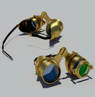
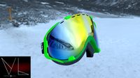
Space Goggles of Awesomeness by DrVegetable
by Thingiverse
Last crawled date: 3 years ago
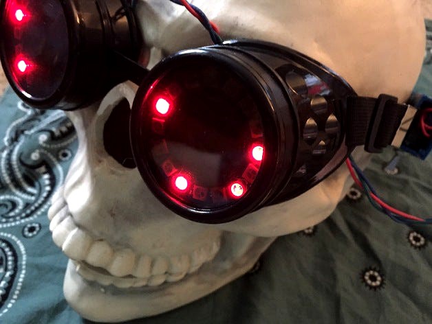
Space Goggles of Awesomeness
The first time I saw a Neopixel ring I knew I would build a pair of goggles with them. The folks at Adafruit must have had the same thought, because they now sell a kit that includes a pair of costume goggles, a pair of Neopixel rings, and (almost) everything you need to make a cool pair of glasses.
https://www.adafruit.com/products/2221
They will amaze your friends and confuse your enemies. Unfortunately, the kit doesn't include a way to mount the rings in the goggles. Scotch tape worked Ok, but visibility through the goggles was very poor. The villains were still getting away!
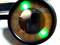
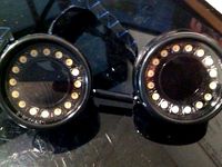
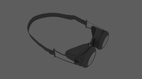
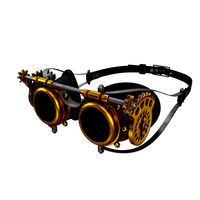
These printable mounting ring inserts hold the rings securely in the goggles without any messy tape, and they improve visibility with a tube to reduce direct and reflected glare.
The case can be discretely attached to the strap to hold the controller and battery securely while you're apprehending bad guys.
I added an SPDT to switch the power ON or OFF to conserve battery charge on longer missions. When you return to your lair, remember that the battery can only be charged when the power is OFF.
I also added a small momentary contact pushbutton between pin #3 and GND. A slow button press longer than 1/2 second will toggle automatic color pattern cycling ON and OFF. A quick button press will advance the color pattern manually.
Construction
NOTE: These instructions involve soldering live battery leads. Extreme caution must be taken to avoid shorting the battery as this can damage the electronics and/or cause serious personal injury! If you are not comfortable doing this, simply omit the SPDT power switch, don't cut the battery leads, and assemble your kit according to the Adafruit instructions.
Print a pair of Neopixel eye surrounds and a controller case and lid. These are provided as an all-in-one STL for your convenience. The eyepieces have slots that will align with the wires of the Neopixel rings and allow the wiring to exit cleanly from the back of the Neopixel PCBs. After wiring and assembly, they can be inserted into the goggle body and will be held in place by the screw-on lens cover.
The Trinket case has slots so it can be attached to the goggle strap. You may find it easier to attach the case to the strap before you install the SPDT power switch and other components. The Adafruit costume goggle strap has a metal cap on each end. (Or maybe it's an "aglet?") It may be necessary to temporarily remove one cap to facilitate disassembly and reassembly of the goggle strap. Gently bend the cap open to remove it. Unwind one end of the strap from the goggles, wind through the case slots as shown, and then reassemble the strap.
Construction is similar to the Adafruit kit, but with an added SPDT power switch (Radio Shack p/n 275-0635 or similar) and a momentary contact pushbutton. Both switches are optional - the firmware presented here will work (with reduced functionality) if you decide not to install either one.
Unlike the Adafruit instructions, do not solder the battery connector onto the bottom of the Trinket as this will interfere with the placement of the battery. Instead, solder wires directly onto the Trinket PCB. The connector that is cut off the battery will be reattached to connect the charger.
The pushbutton is wired directly onto the edge of the Trinket between pin #3 and GND. It is a good idea to test fit the switch in the case before soldering. The unused contacts on the other side of the button should be removed. Because the pushbutton now occupies the GND thru-hole, you may wish to connect the black power input GND wire onto the "-" contact on the underside of the controller board.
When wiring the SPDT power switch, take special care not to short the battery! Do not cut or strip both battery leads at the same time!
0.) Use heat shrink tubing to insulate all connections and switch terminals as you go.
1.) Cut the red lead about halfway between the battery and the connector.
2.) Solder the battery red wire to the center contact of the SPDT switch.
3.) Solder the charge connector red wire to either side of the SPDT.
4.) Solder a wire from the other side of the SPDT to the "BAT" contact on the Trinket, along with the "V+" connector to the Neopixel ring. You may prefer to add a short lead from the Trinket to the wire junction.
5.) Cut the black lead about halfway between the battery and connector and strip both sides.
6.) Wind them together with the "GND" lead to the Neopixel rings and connect them to the "-" contact on the underside of the Trinket board.
For the Trinket you need to use the Arduino 1.6 or later IDE. Under the Tools menu, set the Programmer to "USBTinyISP" and the Board to "Adafruit Trinket 16MHz." The Port name may depend on your operating system. With the SPDT power OFF, connect the USB and watch for flashing red LEDs on the Trinket as you hit Download in the IDE.
The Neopixel ring cannot take power off of the USB port, so you won't see anything until you switch the SPDT to battery power. When you turn it ON, the rings should begin cycling through color patterns after a ~2 second boot time.
Mount the SPDT in the case. Put the battery into the well and secure with double-sided tape if desired. Then mount the Trinket above the battery and secure with two small screws. The screws will self-tap into the undersized plastic guide holes. Ensure that the momentary switch is aligned with the access hole and operates without interference.
The cover will snap into place, and can be secured with glue or tape if desired.
NOTE: Any form of costume eyewear can reduce visibility for the wearer which can pose a hazard to young trick-or-treaters on dark streets. Fortunately, these goggles look just as cool when worn on the forehead as they do over the eyes, and the flashing lights will help motorists and passing aircraft to see your child in the dark.
Happy Halloween!
//
// Adapted from the Adafruit Low Power NeoPixel Goggles example.
//
// This uses a Trinket 5V and a pair of Flora Neopixel 16-element rings
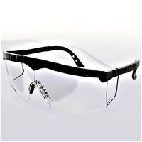
// to turn an ordinary pair of aviation, welders', or costume goggles
// into something extraordinary.
//
// Added support for a momentary-contact pushbuttton from pin #3 to GND.
// Pressing this button for longer than 1/2 second toggles in and out of
// automatic color sequencing mode. A shorter button press advances the
// color sequence manually.
//
// When adding color patterns, remember that power consumption and battery life
// are affected by the number and intensity of pixels that are lit.
//
#include
#ifdef __AVR_ATtiny85__ // Trinket, Gemma, etc.
#include
#endif
// Define the digital I/O pin connected to the Neopixel string:
#define NEOPIXEL_PIN (0)
// Each eyepiece has 16 Neopixel LEDs, so initialize a chain of 32:
#define NEOPIXEL_COUNT (2*16)
Adafruit_NeoPixel pixels = Adafruit_NeoPixel(NEOPIXEL_COUNT, NEOPIXEL_PIN);
// We have a momentary contact pushbutton on I/O pin #3: (shared with USB!)
#define PIN_BUTTON_A 3
uint32_t pressTime;
int buttonState = 0; // 0=released, 1=debounce, 2=pressed
uint8_t mode = 0, // Current animation effect
offset = 0; // Position of spinny eyes
//uint32_t color = 0xFF0000; // Start red
#define N_COLORS (7)
uint32_t colors[N_COLORS] =
{
0xFF0000, // Red
0xFFFF00, // Yellow
0x00FF00, // Green
0x00FFFF, // Cyan
0x0000FF, // Blue
0xFF00FF, // Magenta
0xFFFFFF, // White
};
int nColor = 0;
uint32_t prevTime;
int autoMode = 1;
void advanceMode()
{
mode++; // Next mode
if (mode > 1)
{ // End of modes?
mode = 0; // Start modes over
}
{
//color >>= 8; // Next color R->G->B
//if(!color) color = 0xFF0000; // Reset to red
nColor++;
if (nColor >= N_COLORS)
nColor = 0;
}
for (uint8_t i=0; i<32; i++)
{
pixels.setPixelColor(i, 0);
}
}
void setup() {
#ifdef __AVR_ATtiny85__ // Trinket, Gemma, etc.
if(F_CPU == 16000000) clock_prescale_set(clock_div_1);
#endif
// Set pushbutton pin as input:
pinMode(PIN_BUTTON_A, INPUT_PULLUP);
// Setting input pins to high turns on internal pull-up resistors:
digitalWrite(PIN_BUTTON_A, HIGH);
pixels.begin();
pixels.setBrightness(85); // 1/3 brightness
prevTime = millis();
}
void loop() {
uint8_t i;
uint32_t t;
t = millis();
// Must debounce the button on Pin #3 in case we're powered off USB of an actual computer.
// The USB host will pulse the data line and fake us out otherwise.
if (digitalRead(PIN_BUTTON_A) == LOW)
{
if (buttonState == 0)
{
pressTime = t;
buttonState = 1;
}
else if ((buttonState == 1) && ((t - pressTime) >= 3000 + 60))
{
// Long hold detected (> 3 seconds)
//buttonState = 2;
}
}
else
{
if (buttonState == 1)
{
// Long click (> 1/2 second) changes mode:
if ((t - pressTime) >= 500+60)
{
// Auto color / mode change every 8 seconds ON / OFF
autoMode = !autoMode;
prevTime = t; // Reset next auto-change to 8 seconds
// If entering auto mode, cycle (almost) immediately:
if (autoMode)
{
prevTime = t - 7000; // If I could turn back time...
}
}
// Short click (> 60 msec) changes color:
else if ((t - pressTime) >= 60)
{
// Advance to the next color or mode
advanceMode();
prevTime = t; // Reset next auto-change to 8 seconds
}
}
buttonState = 0;
}
switch (mode)
{
case 0: // Random sparks - just one LED on at a time!
i = random(32);
pixels.setPixelColor(i, colors[nColor]);
pixels.show();
delay(10);
pixels.setPixelColor(i, 0);
break;
case 1: // Spinny wheels (8 LEDs on at a time)
for (i=0; i<16; i++)
{
uint32_t c = 0;
if (((offset + i) & 7) < 2)
{
c = colors[nColor]; // 4 pixels on...
}
pixels.setPixelColor( i, c); // First eye
pixels.setPixelColor(31-i, c); // Second eye (flipped)
}
pixels.show();
offset++;
delay(50);
break;
}
if (autoMode) // Are we in auto-cycle mode?
{
// Check if it is time to cycle to a new mode:
if ((t - prevTime) > 8000) // Every 8 seconds...
{
advanceMode();
prevTime = t;
}
}
}
The first time I saw a Neopixel ring I knew I would build a pair of goggles with them. The folks at Adafruit must have had the same thought, because they now sell a kit that includes a pair of costume goggles, a pair of Neopixel rings, and (almost) everything you need to make a cool pair of glasses.
https://www.adafruit.com/products/2221
They will amaze your friends and confuse your enemies. Unfortunately, the kit doesn't include a way to mount the rings in the goggles. Scotch tape worked Ok, but visibility through the goggles was very poor. The villains were still getting away!
These printable mounting ring inserts hold the rings securely in the goggles without any messy tape, and they improve visibility with a tube to reduce direct and reflected glare.
The case can be discretely attached to the strap to hold the controller and battery securely while you're apprehending bad guys.
I added an SPDT to switch the power ON or OFF to conserve battery charge on longer missions. When you return to your lair, remember that the battery can only be charged when the power is OFF.
I also added a small momentary contact pushbutton between pin #3 and GND. A slow button press longer than 1/2 second will toggle automatic color pattern cycling ON and OFF. A quick button press will advance the color pattern manually.
Construction
NOTE: These instructions involve soldering live battery leads. Extreme caution must be taken to avoid shorting the battery as this can damage the electronics and/or cause serious personal injury! If you are not comfortable doing this, simply omit the SPDT power switch, don't cut the battery leads, and assemble your kit according to the Adafruit instructions.
Print a pair of Neopixel eye surrounds and a controller case and lid. These are provided as an all-in-one STL for your convenience. The eyepieces have slots that will align with the wires of the Neopixel rings and allow the wiring to exit cleanly from the back of the Neopixel PCBs. After wiring and assembly, they can be inserted into the goggle body and will be held in place by the screw-on lens cover.
The Trinket case has slots so it can be attached to the goggle strap. You may find it easier to attach the case to the strap before you install the SPDT power switch and other components. The Adafruit costume goggle strap has a metal cap on each end. (Or maybe it's an "aglet?") It may be necessary to temporarily remove one cap to facilitate disassembly and reassembly of the goggle strap. Gently bend the cap open to remove it. Unwind one end of the strap from the goggles, wind through the case slots as shown, and then reassemble the strap.
Construction is similar to the Adafruit kit, but with an added SPDT power switch (Radio Shack p/n 275-0635 or similar) and a momentary contact pushbutton. Both switches are optional - the firmware presented here will work (with reduced functionality) if you decide not to install either one.
Unlike the Adafruit instructions, do not solder the battery connector onto the bottom of the Trinket as this will interfere with the placement of the battery. Instead, solder wires directly onto the Trinket PCB. The connector that is cut off the battery will be reattached to connect the charger.
The pushbutton is wired directly onto the edge of the Trinket between pin #3 and GND. It is a good idea to test fit the switch in the case before soldering. The unused contacts on the other side of the button should be removed. Because the pushbutton now occupies the GND thru-hole, you may wish to connect the black power input GND wire onto the "-" contact on the underside of the controller board.
When wiring the SPDT power switch, take special care not to short the battery! Do not cut or strip both battery leads at the same time!
0.) Use heat shrink tubing to insulate all connections and switch terminals as you go.
1.) Cut the red lead about halfway between the battery and the connector.
2.) Solder the battery red wire to the center contact of the SPDT switch.
3.) Solder the charge connector red wire to either side of the SPDT.
4.) Solder a wire from the other side of the SPDT to the "BAT" contact on the Trinket, along with the "V+" connector to the Neopixel ring. You may prefer to add a short lead from the Trinket to the wire junction.
5.) Cut the black lead about halfway between the battery and connector and strip both sides.
6.) Wind them together with the "GND" lead to the Neopixel rings and connect them to the "-" contact on the underside of the Trinket board.
For the Trinket you need to use the Arduino 1.6 or later IDE. Under the Tools menu, set the Programmer to "USBTinyISP" and the Board to "Adafruit Trinket 16MHz." The Port name may depend on your operating system. With the SPDT power OFF, connect the USB and watch for flashing red LEDs on the Trinket as you hit Download in the IDE.
The Neopixel ring cannot take power off of the USB port, so you won't see anything until you switch the SPDT to battery power. When you turn it ON, the rings should begin cycling through color patterns after a ~2 second boot time.
Mount the SPDT in the case. Put the battery into the well and secure with double-sided tape if desired. Then mount the Trinket above the battery and secure with two small screws. The screws will self-tap into the undersized plastic guide holes. Ensure that the momentary switch is aligned with the access hole and operates without interference.
The cover will snap into place, and can be secured with glue or tape if desired.
NOTE: Any form of costume eyewear can reduce visibility for the wearer which can pose a hazard to young trick-or-treaters on dark streets. Fortunately, these goggles look just as cool when worn on the forehead as they do over the eyes, and the flashing lights will help motorists and passing aircraft to see your child in the dark.
Happy Halloween!
//
// Adapted from the Adafruit Low Power NeoPixel Goggles example.
//
// This uses a Trinket 5V and a pair of Flora Neopixel 16-element rings
// to turn an ordinary pair of aviation, welders', or costume goggles
// into something extraordinary.
//
// Added support for a momentary-contact pushbuttton from pin #3 to GND.
// Pressing this button for longer than 1/2 second toggles in and out of
// automatic color sequencing mode. A shorter button press advances the
// color sequence manually.
//
// When adding color patterns, remember that power consumption and battery life
// are affected by the number and intensity of pixels that are lit.
//
#include
#ifdef __AVR_ATtiny85__ // Trinket, Gemma, etc.
#include
#endif
// Define the digital I/O pin connected to the Neopixel string:
#define NEOPIXEL_PIN (0)
// Each eyepiece has 16 Neopixel LEDs, so initialize a chain of 32:
#define NEOPIXEL_COUNT (2*16)
Adafruit_NeoPixel pixels = Adafruit_NeoPixel(NEOPIXEL_COUNT, NEOPIXEL_PIN);
// We have a momentary contact pushbutton on I/O pin #3: (shared with USB!)
#define PIN_BUTTON_A 3
uint32_t pressTime;
int buttonState = 0; // 0=released, 1=debounce, 2=pressed
uint8_t mode = 0, // Current animation effect
offset = 0; // Position of spinny eyes
//uint32_t color = 0xFF0000; // Start red
#define N_COLORS (7)
uint32_t colors[N_COLORS] =
{
0xFF0000, // Red
0xFFFF00, // Yellow
0x00FF00, // Green
0x00FFFF, // Cyan
0x0000FF, // Blue
0xFF00FF, // Magenta
0xFFFFFF, // White
};
int nColor = 0;
uint32_t prevTime;
int autoMode = 1;
void advanceMode()
{
mode++; // Next mode
if (mode > 1)
{ // End of modes?
mode = 0; // Start modes over
}
{
//color >>= 8; // Next color R->G->B
//if(!color) color = 0xFF0000; // Reset to red
nColor++;
if (nColor >= N_COLORS)
nColor = 0;
}
for (uint8_t i=0; i<32; i++)
{
pixels.setPixelColor(i, 0);
}
}
void setup() {
#ifdef __AVR_ATtiny85__ // Trinket, Gemma, etc.
if(F_CPU == 16000000) clock_prescale_set(clock_div_1);
#endif
// Set pushbutton pin as input:
pinMode(PIN_BUTTON_A, INPUT_PULLUP);
// Setting input pins to high turns on internal pull-up resistors:
digitalWrite(PIN_BUTTON_A, HIGH);
pixels.begin();
pixels.setBrightness(85); // 1/3 brightness
prevTime = millis();
}
void loop() {
uint8_t i;
uint32_t t;
t = millis();
// Must debounce the button on Pin #3 in case we're powered off USB of an actual computer.
// The USB host will pulse the data line and fake us out otherwise.
if (digitalRead(PIN_BUTTON_A) == LOW)
{
if (buttonState == 0)
{
pressTime = t;
buttonState = 1;
}
else if ((buttonState == 1) && ((t - pressTime) >= 3000 + 60))
{
// Long hold detected (> 3 seconds)
//buttonState = 2;
}
}
else
{
if (buttonState == 1)
{
// Long click (> 1/2 second) changes mode:
if ((t - pressTime) >= 500+60)
{
// Auto color / mode change every 8 seconds ON / OFF
autoMode = !autoMode;
prevTime = t; // Reset next auto-change to 8 seconds
// If entering auto mode, cycle (almost) immediately:
if (autoMode)
{
prevTime = t - 7000; // If I could turn back time...
}
}
// Short click (> 60 msec) changes color:
else if ((t - pressTime) >= 60)
{
// Advance to the next color or mode
advanceMode();
prevTime = t; // Reset next auto-change to 8 seconds
}
}
buttonState = 0;
}
switch (mode)
{
case 0: // Random sparks - just one LED on at a time!
i = random(32);
pixels.setPixelColor(i, colors[nColor]);
pixels.show();
delay(10);
pixels.setPixelColor(i, 0);
break;
case 1: // Spinny wheels (8 LEDs on at a time)
for (i=0; i<16; i++)
{
uint32_t c = 0;
if (((offset + i) & 7) < 2)
{
c = colors[nColor]; // 4 pixels on...
}
pixels.setPixelColor( i, c); // First eye
pixels.setPixelColor(31-i, c); // Second eye (flipped)
}
pixels.show();
offset++;
delay(50);
break;
}
if (autoMode) // Are we in auto-cycle mode?
{
// Check if it is time to cycle to a new mode:
if ((t - prevTime) > 8000) // Every 8 seconds...
{
advanceMode();
prevTime = t;
}
}
}
Similar models
thingiverse
free

InfiniPix by OpenSourceClassroom
...o the trinket, either power the trinket with a 5v power supply or through micro usb cable. screw the frame together and enjoy!!!
thingiverse
free
Neopixel Poi by messingb
...eceives 100 likes, i will post a detailed tutorial so that anyone can learn from my mistakes and maybe even light up their night!
thingiverse
free
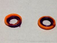
Adafruit Goggle neopixel bezel and backing disc washer by Microtrol
...e battery clip holds a 1200ma li-poly battery and a gemma processor that i bought from adafruit and clips on to the goggle strap.
thingiverse
free

Goggle mount for Adafruit NeoPixel Ring by RedEyedRaven
... sharpie to color it black and it blocks enough light from the leds to be able to see though the goggles with little distraction.
thingiverse
free

EV100 detachabe DVR case by gyjofi
...switch input/output mode. i soldered the 3 pin connectors wire to the goggles main power connector and the main av out connector.
thingiverse
free
Neopixel 5050 Holder Insert for Goggles by 3DKate
... in adafruits kaleidoscope eyes tutorial
https://learn.adafruit.com/kaleidoscope-eyes-neopixel-led-goggles-trinket-gemma/overview
thingiverse
free

Neopixel Tactile Switch Button Case by Firepixie
...n button cover and one with an "om" symbol etched into the top.
video here! https://www.youtube.com/watch?v=7dvy-_mruoo
3dwarehouse
free

pushbutton momentary switch
...pushbutton momentary switch
3dwarehouse
scale model of a momentary switch #button #momentary #pushbutton #switch
thingiverse
free

Doctor Strange - Eye of Agamotto (remix) by nmsr1196
... shown) by adding newopixel jewel 7 [adafruit part#2226] with gemma. i will need to add a recharge board for this future option.
thingiverse
free
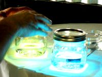
neopixel jar lid by Mentaluproar
.... powered by adafruit trinket and 12 led neopixel ring with a 9 volt battery. fit this under the lid of a wide mouth mason jar.
Drvegetable
thingiverse
free

CubeSphere Dual Extruder Test by DrVegetable
...cubesphere dual extruder test by drvegetable
thingiverse
i designed this to test my dual extruder. enjoy!
thingiverse
free

Pi4 Back cover for DrVegetable case
...t the moment i don't have it a portable unite yet. just incase you don't want to make it portable and just keep the cord.
thingiverse
free
ConcentricRings Dual Extruder Calibration by DrVegetable
... still on the bed, and new offset values were calculated to result in perfect alignment in the second print, on the right.
enjoy!
thingiverse
free

Carry Handle and Corner Protectors by DrVegetable
...e another. the x4 .stl file is four identical copies of the single corner, for easier printing of full sets.
no supports needed.
thingiverse
free

Minecraft Ore Night Light by DrVegetable
....
the block is 64mm on a side.
printed on a dual extruder using natural pla for the veins and grey for the body with 100% infill.
thingiverse
free

3D Print Bed Glass Corner Clips by DrVegetable
...ood idea to use abs.
the two .stl files are the same design, but the second file has four copies to simplify printing a full set.
thingiverse
free
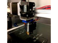
E3D Adapter for Velleman K8200 with K8203 Direct Drive by DrVegetable
...ngth of filament between the drive and the hot end during installation, to help judge good alignment of the top of the ptfe tube.
thingiverse
free

Velleman K8800 Delta LM10UU Linear Bearing Upgrade by DrVegetable
...et me know how these work for you.
full write-up: https://forum.vellemanprojects.eu/t/the-solution-for-all-your-delta-woes/29088
thingiverse
free
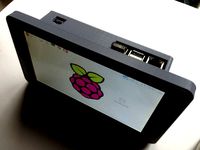
Raspberry Pi 7" Touchscreen Super Awesome Portable by DrVegetable
...lent adafruit page describing the original project:
https://learn.adafruit.com/7-portable-raspberry-pi-multitouch-tablet/overview
Goggles
3ddd
$1

Goggle desk
...goggle desk
3ddd
goggle desk , стол
goggle desk стол для современных и амбициозных
3ddd
$1

Goggle Desk
... goggle desk , стол
goggle desk – стол для амбициозных и современных
turbosquid
$74

Goggles
... available on turbo squid, the world's leading provider of digital 3d models for visualization, films, television, and games.
turbosquid
$30

Goggles
... available on turbo squid, the world's leading provider of digital 3d models for visualization, films, television, and games.
3d_ocean
$17
Steampunk Goggles
...bj and max 10,11 and 13 version format. materials are included and it is based on mental ray renderer. also, main file include...
3d_ocean
$5

Goggle Desk
...al design by danny venlet for babini • all objects are properly named and grouped • model is fully textured with all materials...
3d_export
$20
safety goggles glasses
...safety goggles glasses
3dexport
safety goggles glasses
turbosquid
$10
Steampunk Goggles
...d
royalty free 3d model steampunk goggles for download as ma on turbosquid: 3d models for games, architecture, videos. (1537373)
turbosquid
$25
Steampunk Goggles
...el steampunk goggles for download as max, obj, fbx, and blend on turbosquid: 3d models for games, architecture, videos. (1490759)
turbosquid
$15
Ski goggles
...3d model ski goggles for download as 3ds, obj, fbx, and blend on turbosquid: 3d models for games, architecture, videos. (1271456)
Awesomeness
turbosquid
free

Awesome
... available on turbo squid, the world's leading provider of digital 3d models for visualization, films, television, and games.
turbosquid
$20
Awesome Chair
...quid
royalty free 3d model awesome chair for download as c4d on turbosquid: 3d models for games, architecture, videos. (1212050)
3d_export
$20

awesome bike
...awesome bike
3dexport
great for exteriors
turbosquid
$15
Awesome Couch
... available on turbo squid, the world's leading provider of digital 3d models for visualization, films, television, and games.
turbosquid
$10
Awesome Crane
... available on turbo squid, the world's leading provider of digital 3d models for visualization, films, television, and games.
turbosquid
free
Awesome Chair
... available on turbo squid, the world's leading provider of digital 3d models for visualization, films, television, and games.
turbosquid
$1

Awesome clock's
... available on turbo squid, the world's leading provider of digital 3d models for visualization, films, television, and games.
turbosquid
$1

awesome coffee cup
...oyalty free 3d model awesome coffee cup for download as blend on turbosquid: 3d models for games, architecture, videos. (1277009)
turbosquid
free

Awesome rigged eyes
...d
free 3d model free awesome rigged eyes for download as max on turbosquid: 3d models for games, architecture, videos. (1596325)
turbosquid
free
5 Awesome Fanasty Interiors
... available on turbo squid, the world's leading provider of digital 3d models for visualization, films, television, and games.
Space
3ddd
free
Space
... space , вытяжка
вытяжка elica space, производство elica evolution
3d_ocean
$19
Space station
...space station
3docean
space station
space station
3d_ocean
$7
Space Fighter
...space fighter
3docean
fighter space
space fighter
turbosquid
$5
space
...e
turbosquid
royalty free 3d model space for download as max on turbosquid: 3d models for games, architecture, videos. (1184221)
turbosquid
$2
Space
...turbosquid
royalty free 3d model space for download as blend on turbosquid: 3d models for games, architecture, videos. (1660625)
3d_ocean
$4
Space Station
...space station
3docean
habitat low poly ship space space ship space station vehicle
space station low poly modelled, not textured.
turbosquid
$2
Space
...royalty free 3d model space for download as max, fbx, and obj on turbosquid: 3d models for games, architecture, videos. (1644726)
turbosquid
$8

Space
...ty free 3d model space for download as c4d, 3ds, fbx, and obj on turbosquid: 3d models for games, architecture, videos. (1521166)
turbosquid
$160
space
... available on turbo squid, the world's leading provider of digital 3d models for visualization, films, television, and games.
turbosquid
$5
Space
... available on turbo squid, the world's leading provider of digital 3d models for visualization, films, television, and games.