Thingiverse
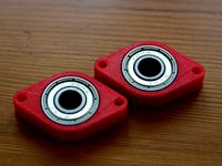
SmartRapCore Alu - DjDemonD Adjustable Motor mounts, Belt Geometry fix for 608zz bearing pulleys by DjDemonD
by Thingiverse
Last crawled date: 3 years ago
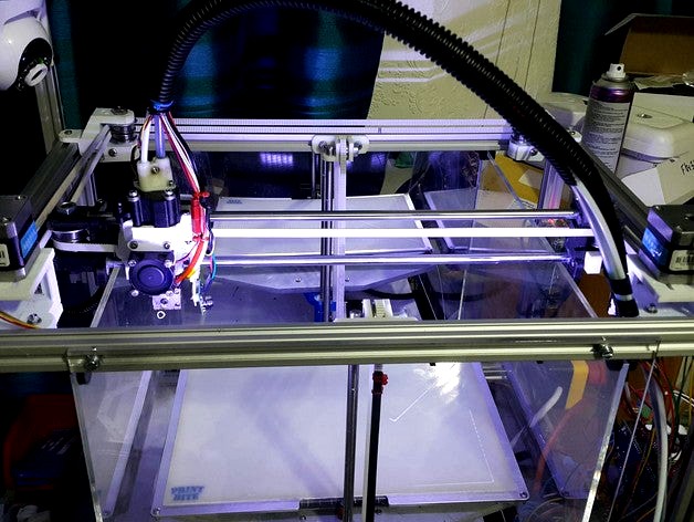
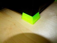
Update 31-08-16 the machine is much quieter with these mounts the motors are much better isolated from the frame acoustically,which is a nice unexpected improvement.
Okay so there are several issues with the SmartRapCore Alu:
1) as with all corexy machines getting the machine to print correct sized parts in x relative to y is done by adjusting the belt tension from the A belt relative to the B belt. This is difficult on the SCALU machine as the only way to do it is to pull belts out of belt clips and move them one belt tooth (2mm) one way or the other. I tried to get around this by making a balanced belt tension carriage but it still doesn't work perfectly.
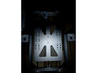
2) The motor mounts also being the y-rod holders at the front are not great. I have never been happy my y-rods were perfectly aligned or held firmly enough to ensure good print quality. Plus the left and right sides had different mountings, this never seems like a good idea.
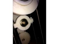
3) The big one - belt angles, this thread http://forums.reprap.org/read.php?344,563301,703546#msg-703546 on reprap forum makes clear the reasons why the belts must be parallel to one another along the x direction, and must turn at exactly 90 deg from the y slides to the back idler pulley and front drive pulley. Any deviation from this and objects will not be square, especially at the edges of the bed. In the original SCALU design this might have been correct but with 608 bearings the geometry changes, and the pulleys are not perfectly aligned with the y-carriages.
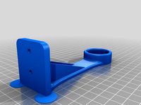
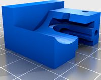
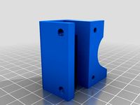
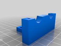
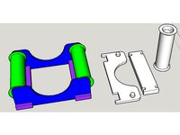
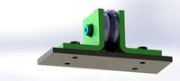
So these motor mounts are designed to solve all three problems.
1) The x and y (a and b) motors can now slide around 10mm, to easily adjust the relative belt tension.
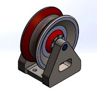
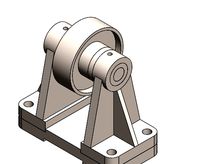
2) They are derived from the rear pulley holders, my version which has fully supported pulleys (http://www.thingiverse.com/thing:1655402), so they hold the y-rods firmly and precisely in alignment with the rear pulley holders, no more odd asymmetrical fixings as found in the original SCALU design.
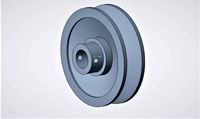
3) The pulleys are now positioned so that the belt turns exactly 90 degrees from the y-carriages to the drive pulley. Please be aware my machine has f608zz bearings and not printed pulley sleeves so the geometry for the pulleys is based around that. I have no intention of doing a version for printed pulley sleeves as they are not accurate and 608 bearings are cheap and cheerful. If you replace your pulley sleeves consider printing y-slides which are designed for them with more relief for the belts, or the belts will rub, also you'll need to change your x carriage as the belt clips are more spaced out for pulley sleeves than for 608 bearings.
Made in Tinkercad, and I am bad at CAD so if anyone who is much better than I am wishes to neaten them up and fillet them etc... then please do. :)
That being said they are perfectly functional.
Some pointers.
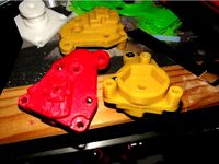
-I printed mine in PETG, they are very strong, they would work in ABS but PLA might be asking a lot, there are big forces on these parts and it will crack, maybe the reinforced material or annealed versions might work.
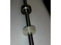
-Your current rods should fit okay. On the rear idler pulley holders the large m8 bolt clamps the y-rod, I have changed this to an m3 bolt and locknut with some washers to spread the force out, make sure these are tightened after installation to keep the rods held firmly.
-You can use the four m4 bolts and four m4 half drop-in t nuts (2 per side) from your old motor mounts, but you will also need 2x60mm m4 bolt (57mm to be precise but I used some washers), and 2xm4 drop in t nuts.
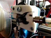
-I have not designed an endstop mount, but as you can see from the images I placed one by drilling a 2.75mm hole and screwing the endstop in here. I added a small printed cube bonded with superglue to the y-slide to ensure it can hit the endstop. Future versions will have the endstop hole here, and my version of the y-slides will have an extension for the endstop.
-Attach the motors before installing the units in your machine (I learnt the hard way its easier beforehand - trust me). Use the most accessible three of the holes for your bolts, this will be strong enough, and when you want to adjust the belt tension to calibrate the A and B sides of a cube its easier to undo 3 accessible bolts without the 4th inaccessible one making the job hard. I used good ol' fashioned m3 hex bolts not cap headed machine screws. The same problem as trying to get an allen key/hex driver into a kossel's corners applies here, use normal bolts and a 5.5mm spanner. If you have a 5.5mm ratchet spanner use that, considering buying one.
-In firmware REVERSE YOUR X AND Y STEPPER DIRECTION, in Marlin they should read false under #define INVERT_X_DIR and #define INVERT_Y_DIR as the motors are now upside down. Your y-dimension might change by 5mm or so, change these settings also.
Please excuse the PETG prints the quality is not what I usually produce, they're dimensionally accurate but the surface finish needs some tweaking.
Please do mess with these designs I have made the files public in tinkercad but let me know if you improve on it:https://www.tinkercad.com/things/hLgH3rUWW9M-scalu-adjustable-motor-mounts-608zz-bearing-version/
Okay so there are several issues with the SmartRapCore Alu:
1) as with all corexy machines getting the machine to print correct sized parts in x relative to y is done by adjusting the belt tension from the A belt relative to the B belt. This is difficult on the SCALU machine as the only way to do it is to pull belts out of belt clips and move them one belt tooth (2mm) one way or the other. I tried to get around this by making a balanced belt tension carriage but it still doesn't work perfectly.
2) The motor mounts also being the y-rod holders at the front are not great. I have never been happy my y-rods were perfectly aligned or held firmly enough to ensure good print quality. Plus the left and right sides had different mountings, this never seems like a good idea.
3) The big one - belt angles, this thread http://forums.reprap.org/read.php?344,563301,703546#msg-703546 on reprap forum makes clear the reasons why the belts must be parallel to one another along the x direction, and must turn at exactly 90 deg from the y slides to the back idler pulley and front drive pulley. Any deviation from this and objects will not be square, especially at the edges of the bed. In the original SCALU design this might have been correct but with 608 bearings the geometry changes, and the pulleys are not perfectly aligned with the y-carriages.
So these motor mounts are designed to solve all three problems.
1) The x and y (a and b) motors can now slide around 10mm, to easily adjust the relative belt tension.
2) They are derived from the rear pulley holders, my version which has fully supported pulleys (http://www.thingiverse.com/thing:1655402), so they hold the y-rods firmly and precisely in alignment with the rear pulley holders, no more odd asymmetrical fixings as found in the original SCALU design.
3) The pulleys are now positioned so that the belt turns exactly 90 degrees from the y-carriages to the drive pulley. Please be aware my machine has f608zz bearings and not printed pulley sleeves so the geometry for the pulleys is based around that. I have no intention of doing a version for printed pulley sleeves as they are not accurate and 608 bearings are cheap and cheerful. If you replace your pulley sleeves consider printing y-slides which are designed for them with more relief for the belts, or the belts will rub, also you'll need to change your x carriage as the belt clips are more spaced out for pulley sleeves than for 608 bearings.
Made in Tinkercad, and I am bad at CAD so if anyone who is much better than I am wishes to neaten them up and fillet them etc... then please do. :)
That being said they are perfectly functional.
Some pointers.
-I printed mine in PETG, they are very strong, they would work in ABS but PLA might be asking a lot, there are big forces on these parts and it will crack, maybe the reinforced material or annealed versions might work.
-Your current rods should fit okay. On the rear idler pulley holders the large m8 bolt clamps the y-rod, I have changed this to an m3 bolt and locknut with some washers to spread the force out, make sure these are tightened after installation to keep the rods held firmly.
-You can use the four m4 bolts and four m4 half drop-in t nuts (2 per side) from your old motor mounts, but you will also need 2x60mm m4 bolt (57mm to be precise but I used some washers), and 2xm4 drop in t nuts.
-I have not designed an endstop mount, but as you can see from the images I placed one by drilling a 2.75mm hole and screwing the endstop in here. I added a small printed cube bonded with superglue to the y-slide to ensure it can hit the endstop. Future versions will have the endstop hole here, and my version of the y-slides will have an extension for the endstop.
-Attach the motors before installing the units in your machine (I learnt the hard way its easier beforehand - trust me). Use the most accessible three of the holes for your bolts, this will be strong enough, and when you want to adjust the belt tension to calibrate the A and B sides of a cube its easier to undo 3 accessible bolts without the 4th inaccessible one making the job hard. I used good ol' fashioned m3 hex bolts not cap headed machine screws. The same problem as trying to get an allen key/hex driver into a kossel's corners applies here, use normal bolts and a 5.5mm spanner. If you have a 5.5mm ratchet spanner use that, considering buying one.
-In firmware REVERSE YOUR X AND Y STEPPER DIRECTION, in Marlin they should read false under #define INVERT_X_DIR and #define INVERT_Y_DIR as the motors are now upside down. Your y-dimension might change by 5mm or so, change these settings also.
Please excuse the PETG prints the quality is not what I usually produce, they're dimensionally accurate but the surface finish needs some tweaking.
Please do mess with these designs I have made the files public in tinkercad but let me know if you improve on it:https://www.tinkercad.com/things/hLgH3rUWW9M-scalu-adjustable-motor-mounts-608zz-bearing-version/
Similar models
thingiverse
free

SmartRapCore Alu Improved Y-slides more belt clearance L&R by DjDemonD
...h hold the rods in place, you'll need to print 3 of the reinforced ones, and one of the ones with the tab for your x endstop.
thingiverse
free

ANET A4 Carriage, Belt Tensioner and Tower Endcap Remixes
...so all the versions to be compared and redesigned if needed.https://www.tinkercad.com/things/imykjiuowyr-anet-a4-carriage-remixes
thingiverse
free

Prusa y axis removable motor mount - no idler - adjustable belt tension by gitrdun
...ed so it can be removed from the machine easily.the bolt holes for mounting the motor are slotted so you can tension up the belt.
thingiverse
free

Prusa i3 Updated Y Carriage by Terrapinmfg
...dated bed plate as well.
there is a stp file of the assembly as well as the .stl files for the printed parts and the bed plate.
thingiverse
free

LM8UU Y-Axis Adjustable Endstop Spacer by PhilKloppers
...ve fits over the 8mm smooth rod and slides onto the lm8uu bearing securely. a 10mm m3 bolt serves to adjust the endstop distance.
thingiverse
free

Hictop Acrylic Y enstop by kmags
...the carriage it kept breaking the wires due to motion. it is needed if you use the adjustable y belt tensioner (thing# 1175810).
thingiverse
free

Better Y axis for flsun cube with belt tensioner by MichaelLamb
...at will loosen over time causing headaches... unfortunately that does not correct crooked 8mm rods that came with the printer...
thingiverse
free

Y belt tensioner for FLSUN cube by GregLen
...the standard h wheel holder as in my x tensioner.
the ysupport has a cut out on one side to enable it to fit against the x motor.
thingiverse
free

New Y clamp for hypercube evo (tension release) by zjxlsti
... am talking about, and confident about your x gantry set up (both x rods tightened so no force is transferred to your y bearings)
thingiverse
free
AM8 - 200x300 buildplate - 350mm Z height by bipsen
...h additional material added for better strength (i saw some like these somewhere - but cannot remember if it was on thingiverse).
Djdemond
thingiverse
free
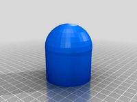
50mm Towball cover Hitch Cap by DjDemonD
...50mm towball cover hitch cap by djdemond
thingiverse
cover for 50mm towball.
thingiverse
free
Duet3D Smarteffector Nimble Mount DjDemonD Remix by DjDemonD
...ess sensitive. you also need to consider the orientation of the large nut to you heatsink when assembling the hotend into the se.
thingiverse
free

Brio Wooden Train Tunnel by DjDemonD
...valley etc.. multiple units can be joined to make a longer tunnel. 80mm diameter so even fairly large trains can make it through.
thingiverse
free

Bowden pushfit locking ring for clone titan and y-splitter by DjDemonD
...for clone titan and y-splitter by djdemond
thingiverse
locking clip for trianglelabs clone titan and y-splitter bowden fittings.
thingiverse
free
3-Way Approach for Brio Thomas Engine Shed by DjDemonD
...ond
thingiverse
i bought one of these engine sheds but didn't have the approach track which is a custom piece so i made one.
thingiverse
free

Precision Piezo - 27mm and 20mm Piezo Disc drill guide. by DjDemonD
... djdemond
thingiverse
drilling guide for piezo discs to centre your drill.
see youtube video here: https://youtu.be/ms1fd0v5z68
thingiverse
free

Mechanical Z Endstop for DjDemonD/AndreasL Dual z axis smartrapcore alu by DjDemonD
...babystep z on the first print and used m206 to enter the home offset. (nb. if the nozzle was 1mm too high the m206 z would be 1.)
thingiverse
free
Paper Towel Holder Strengthened Remix by DjDemonD
...t to allow for the strengthening braces. since altering it, it works perfectly in fact i am even using some as spool holders too.
thingiverse
free
Sensor Test Rig by DjDemonD
...aver. i am not going to provide full build instructions, if you cannot figure out how to build it, should you be testing sensors?
thingiverse
free

Technics 1200 Turntable with spinning record by DjDemonD
... fits over a 5mm motor shaft and spins as my printer prints.
just bond it all together after assembly with superglue or acetone.
Smartrapcore
thingiverse
free

Smartrapcore 1.2.2 by caesarmaker
...smartrapcore 1.2.2 by caesarmaker
thingiverse
smartrapcore plastic parts
thingiverse
free
Smartrapcore 1.2.2 by caesarmaker
...smartrapcore 1.2.2 by caesarmaker
thingiverse
smartrapcore plastic parts
thingiverse
free

smartrapcore by tenij000
...smartrapcore by tenij000
thingiverse
endstop
thingiverse
free
![[ SmartrapCore ] by Makoto by Makoto_Doushite](/t/8617695.jpg)
[ SmartrapCore ] by Makoto by Makoto_Doushite
...ent bowden extruder with push fit pc6-m6 : https://www.thingiverse.com/thing:2691683 [ replaced because too weak for good print ]
thingiverse
free

Smartrapcore fanduct by yann44
...of bottom airflowhttps://cad.onshape.com/documents/4fea958d6bd043ae81cdb6af/w/8f126fa5f8144d13a14a42f9/e/2a8afe8ff3ce4d6fa22a4a8e
thingiverse
free

Adjustable Z Endstop for SmartrapCore by gsyan
...adjustable z endstop for smartrapcore by gsyan
thingiverse
use a micro switch as smartrapcore z endstop.
thingiverse
free

Adaptateur Volcano head SmartrapCore by ratcut
...adaptateur volcano head smartrapcore by ratcut
thingiverse
adapteur pour tête volcano sur smartrapcore
thingiverse
free
Foot for wood SmartrapCore by grami_fr
... wood smartrapcore.
it was a test to reduce vibration on the desk.
and it works....i think it's better with this litlle foot.
thingiverse
free

FilamentHolder for Smartrapcore ALU by sun121025
...21025
thingiverse
filamentholder for smartrapcore alu
20mmx20mm frame
cura 0.2mm layer height
20%
printer speed 50
take me 1h40m
thingiverse
free
Dual Hotend for Smartfriend Smartrapcore by Davemoon
...rapcore by davemoon
thingiverse
this is a dual hotend holder for my smartrapcore printer. it uses the original holes and screws.
608Zz
thingiverse
free

608zz cover by Parrita710
...608zz cover by parrita710
thingiverse
a cover for 608zz
thingiverse
free
608zz Alternative by Lusid
...608zz alternative by lusid
thingiverse
3d printed 608zz
thingiverse
free
608zz bearing bracket | soporte para rodamiento 608zz by felimanue
...608zz bearing bracket | soporte para rodamiento 608zz by felimanue
thingiverse
bracket for 608zz bearing. with m3 fastener.
thingiverse
free

608zz plug by TK_DESIGN
...608zz plug by tk_design
thingiverse
double 608zz holder plug for makelangelo stepper motor.
thingiverse
free

Tri_Spinner 608ZZ by GreenPrinter
...tri_spinner 608zz by greenprinter
thingiverse
1 x ball bearing 608zz (22mm)
5 x nuts (14mm).
thingiverse
free
608zz Spacer by s_s_
...608zz spacer by s_s_
thingiverse
spacer for the 608zz which i needed for my p3steel as the steel case rasped on the y-belt
thingiverse
free
608zz bearing pillow by algenist
...608zz bearing pillow by algenist
thingiverse
for 608zz bearing and m3 bolts
thingiverse
free
Foldarap Extruder 608zz by atancito
...foldarap extruder 608zz by atancito
thingiverse
foldarap extruder with 608zz bearing
thingiverse
free
SpoolHolder with 608zz by techvhonto
...giverse
four bearings are needed for assembly(608zz).
each component needs to be printed two times and no supporters are needed.
thingiverse
free
608ZZ bearing holder by bundyr
...608zz bearing holder by bundyr
thingiverse
608zz bearing holder with m3 holes
Alu
3ddd
free
LEDS-C4 Alu
...leds-c4 alu
3ddd
leds-c4
leds-c4 alu
3ddd
$1

Beluga Alu
...ный
светильник напольный 370*370*390 мм
материал : алюминий
e27 1 x 75w ipar / 14,5w led / 30w fbt
ip65
дизайн marck sadler
3ddd
$1

Зонт SHA ALU
...зонт sha alu
3ddd
зонт
http://www.royalbotania.com/products/sha-alu
3ddd
$1

Диван NATAL ALU SOFA
... угловой
диван natal alu sofa
производитель tribu
модель в размерах
текстуры в архиве
3d max 2014+obj
turbosquid
$2

Handle alu-lkw4
... available on turbo squid, the world's leading provider of digital 3d models for visualization, films, television, and games.
3ddd
$1
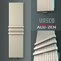
Vasco. Alu-zen
...a flat aluminium designer heated towel rails with rounded side profiles.
measure: 2000 x 525 mm.
file: max 2010, 2012; fbx; obj.
3ddd
$1

Coffee Table Spidernet Alu
... кофейный
кофейный столик coffee table spidernet alu
material:
алюминий
size:
0,34 x 0,89 x 0,89 m
weight:
17,75 кг
turbosquid
$5

Coffee Cup Alu Version
... available on turbo squid, the world's leading provider of digital 3d models for visualization, films, television, and games.
3ddd
$1
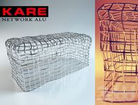
KARE / Network Alu
... банкетка , скамья
220 000 polys
сайт производителя:http://www.karedesign.de/
design_connected
$13

Alusion Lounge ALU 195 T.
...ignconnected
royal botania alusion lounge alu 195 t. seating objects computer generated 3d model. designed by kris van puyvelde.
Pulleys
3d_export
$1

pulley
...pulley
3dexport
3d_export
$30
Pulley export
...pulley export
3dexport
pulley export design render 3d modelling
3d_export
free
Pulley
...ort
this is a pulley<br>formats: ".3ds", ".fbx", ".obj", ".stl", "blend"
3d_export
$6
roller pulley
...r pulley
3dexport
this is the roller pulley 3d model its used for 3d printers and some other uses for toys and usefull things .
turbosquid
$2
aluminum pulley
...
royalty free 3d model aluminum pulley for download as sldpr on turbosquid: 3d models for games, architecture, videos. (1671716)
turbosquid
$29

pulley wheel
...d model pulley wheel for download as obj, wrl, fbx, and blend on turbosquid: 3d models for games, architecture, videos. (1319384)
turbosquid
free

Pulley.3ds
... available on turbo squid, the world's leading provider of digital 3d models for visualization, films, television, and games.
3d_export
$10
design and assembly of pulley
...design and assembly of pulley
3dexport
design and assembly of pulley 3d model which is used for drive and driven
3d_export
$10

Pulley 3D Model
...y sewing sewingmachine c4d fbx metal
pulley 3d model download .c4d .max .obj .fbx .ma .lwo .3ds .3dm .stl dixiony 107270 3dexport
3d_export
$10

Pulley 3D Model
...trial machine c4d fbx cinema4d metal
pulley 3d model download .c4d .max .obj .fbx .ma .lwo .3ds .3dm .stl dixiony 107271 3dexport
Belt
turbosquid
$9
Belt conveyor belt
...t conveyor belt for download as 3ds, ige, obj, stl, and sldas on turbosquid: 3d models for games, architecture, videos. (1226546)
3d_export
$6
belt
...d then comes off and fastens at the front of the seat. version: 2015 units: millimetres x-form: yes polys: 120 950 verts: 163 944
3d_export
$7
belt grinder
...belt grinder
3dexport
belt grinder
3d_export
$5
Belt conveyor
...belt conveyor
3dexport
belt conveyor
3ddd
$1
column belt
...column belt
3ddd
колонна
column belt
turbosquid
$5
Belt
... available on turbo squid, the world's leading provider of digital 3d models for visualization, films, television, and games.
3d_ocean
$5
Leather Belt
...ather belt is created in 3dsmax 2011 and rendered with vray 1.5 and it has all the texture included with the multiple obj format.
3d_ocean
$5
Belt Ring
...belt ring
3docean
belt jewelry ring
belt ring 3d model. total weight 3.5 gram & 1.1 stone size. 3dm and obj file format.
design_connected
$11
Belt Round
...belt round
designconnected
meridiani belt round computer generated 3d model. designed by parisio, andrea.
design_connected
$11
Belt Oval
...belt oval
designconnected
meridiani belt oval computer generated 3d model. designed by parisio, andrea.
Bearing
3d_export
$6
Bear
...bear
3dexport
bear
3d_export
$5
bearing
...bearing
3dexport
bearing
3d_export
$12

bear
...bear
3dexport
bear for 3d printing toy
3d_ocean
$9
Bearing
...ne ball ballbea bearing bearings engine hard industrial machine mechanic metal part piece plastic ring screw sphere steel
bearing
archibase_planet
free

Bear
...bear
archibase planet
statuette bear picturesque element
bear - 3d model (*.gsm+*.3ds) for interior 3d visualization.
3d_export
$5

bear
...bear
3dexport
bear have a stl.,3dm files
archibase_planet
free

Bear
...bear
archibase planet
bear animals omnivorous animal
bear angry n250907- 3d model (*.gsm+*.3ds) for interior 3d visualization.
archibase_planet
free

Bear
...bear
archibase planet
bear animals omnivorous animal
bear easy n250907 - 3d model (*.gsm+*.3ds) for interior 3d visualization.
3ddd
$1

Teddy bear
...teddy bear
3ddd
teddy bear , медведь
teddy bear :)
3d_ocean
$12
Bear
... formats. created with 3d max 9.0. this file is very useful for learning & rigging. it can be used for any professional work.
Geometry
design_connected
$7
Geometry Stool
...geometry stool
designconnected
ligne roset geometry stool computer generated 3d model. designed by ducru, jacques.
turbosquid
free

Abstract geometry
...rbosquid
free 3d model abstract geometry for download as c4d on turbosquid: 3d models for games, architecture, videos. (1340199)
turbosquid
$1
Geometry Box
...oyalty free 3d model geometry box for download as max and fbx on turbosquid: 3d models for games, architecture, videos. (1608060)
turbosquid
$10

Geometry Chair
...ree 3d model geometry chair for download as max, obj, and fbx on turbosquid: 3d models for games, architecture, videos. (1699186)
turbosquid
$3

icecream ( geometry )
... available on turbo squid, the world's leading provider of digital 3d models for visualization, films, television, and games.
turbosquid
free

Web Geometry
... available on turbo squid, the world's leading provider of digital 3d models for visualization, films, television, and games.
turbosquid
$4

infinite geometry
...e geometry for download as 3ds, obj, fbx, blend, dae, and stl on turbosquid: 3d models for games, architecture, videos. (1272938)
turbosquid
$4

the geometry of the cubes
...nload as 3ds, max, dxf, obj, wrl, fbx, w3d, pwc, dwg, and dae on turbosquid: 3d models for games, architecture, videos. (1368178)
design_connected
$11

Geometry Made Easy
...geometry made easy
designconnected
micromacro geometry made easy computer generated 3d model. designed by bernardi, sara .
turbosquid
$5

Geometry Nesting table
...alty free 3d model geometry nesting table for download as fbx on turbosquid: 3d models for games, architecture, videos. (1655135)
Fix
3ddd
$1
Fixed Gear Велосипед
... fixed , bicycle
классический шоссейный велосипед, переделанный под fixed gear.
design_connected
$16

Idée fixe
...idée fixe
designconnected
jacco maris idée fixe computer generated 3d model. designed by maris , jacco.
3d_export
$5

fixing scale knob
...fixing scale knob
3dexport
fixing scale knob
turbosquid
$10

Mini Fix
...bosquid
royalty free 3d model mini fix for download as sldas on turbosquid: 3d models for games, architecture, videos. (1581558)
turbosquid
$49

fixed bike
... available on turbo squid, the world's leading provider of digital 3d models for visualization, films, television, and games.
turbosquid
$39

Fixed Bicycle
... available on turbo squid, the world's leading provider of digital 3d models for visualization, films, television, and games.
3ddd
$1
Bag Fixed
...bag fixed
3ddd
чемодан
a bag model by me
3ddd
$1

Кресло BEAU FIXE
...fixe
3ddd
beau fixe , ligne roset
кресло beau fixe:
w 80 cm d 106 cm h 97 cm sh 43,5 cm
turbosquid
free

Crowbar "Fixed"
... available on turbo squid, the world's leading provider of digital 3d models for visualization, films, television, and games.
3ddd
$1
Fixed gear
...fixed gear
3ddd
велосипед
шоссейный велосипед с фиксированной передачей
Motor
archibase_planet
free
Motor
...base planet
motor motor engine engine electric motor
motor wagner n250213 - 3d model (*.gsm+*.3ds) for interior 3d visualization.
archibase_planet
free
Motor
...motor
archibase planet
motor motor engine engine
motor n151112 - 3d model (*.gsm+*.3ds) for interior 3d visualization.
archibase_planet
free
Motor
...motor
archibase planet
motor motor engine engine
motor n150615 - 3d model (*.gsm+*.3ds+*.max) for interior 3d visualization.
turbosquid
$15
Motor
...otor
turbosquid
royalty free 3d model motor for download as on turbosquid: 3d models for games, architecture, videos. (1639404)
3d_ocean
$5
Electric motor
...electric motor
3docean
car electric engine industry motor phase train vehicle
an electric motor enjoy!
3d_ocean
$18
Electric Motor
...electric motor
3docean
electric motor engine machine mover parts
3d model electric motor for hoist crane
turbosquid
$29
Motor
... available on turbo squid, the world's leading provider of digital 3d models for visualization, films, television, and games.
turbosquid
$5
Motor
... available on turbo squid, the world's leading provider of digital 3d models for visualization, films, television, and games.
3d_export
$5
electric motor
...electric motor
3dexport
electric motor use for industrial purposes
3d_export
$5
servo motor
...tor
3dexport
it's a simple part of servo motor 0.75kw for used in machines assembly to show specified motor in own project.
Adjustable
3d_ocean
$7
Adjustable Wrench
...adjustable wrench
3docean
adjustable wrench highly detailed wrench
highly detailed adjustable wrench.
3ddd
$1
Adjustable Stool
...adjustable stool
3ddd
табурет
wooden adjustable stool.
3d_ocean
$20

Adjustable Gym Bench
...st adjustable bench black equipement gym gymnastic indoor silver sport workout
3d model of black and silver adjustable gym bench.
3d_ocean
$20
Adjustable Gym Bench
...st adjustable bench black equipement gym gymnastic indoor silver sport workout
3d model of black and silver adjustable gym bench.
3d_ocean
$16

Adjustable Weight Bench
...arbell bench black equipement gym gymnastic indoor sport weight workout
3d model of black adjustable weight bench with a barbell.
turbosquid
$5

Adjustable wrench
...
royalty free 3d model adjustable wrench for download as fbx on turbosquid: 3d models for games, architecture, videos. (1313414)
3d_export
$5
adjustable tension lock
...adjustable tension lock
3dexport
adjustable tension lock
turbosquid
$1

Adjustable Wrench
...free 3d model adjustable wrench for download as obj and blend on turbosquid: 3d models for games, architecture, videos. (1446736)
turbosquid
$1

Adjustable Wrench
...y free 3d model adjustable wrench for download as c4d and fbx on turbosquid: 3d models for games, architecture, videos. (1379022)
3d_export
$5
Adjustable key
...adjustable key
3dexport
Mounts
3d_export
free

mounting bracket
...the part of a hinge, handle or latch that mounts the hardware to a cabinet. mounting plates make it...
turbosquid
$2

MOUNTING
... available on turbo squid, the world's leading provider of digital 3d models for visualization, films, television, and games.
turbosquid
free

Mounts
... available on turbo squid, the world's leading provider of digital 3d models for visualization, films, television, and games.
turbosquid
free

Mount Fuji
...fuji
turbosquid
free 3d model mount fuji for download as obj on turbosquid: 3d models for games, architecture, videos. (1579977)
3d_export
$5

Headphone mount LR
...headphone mount lr
3dexport
headphone mount l+r
turbosquid
$39

Mount rainier
...quid
royalty free 3d model mount rainier for download as fbx on turbosquid: 3d models for games, architecture, videos. (1492586)
turbosquid
$5

pipe mounting
...quid
royalty free 3d model pipe mounting for download as obj on turbosquid: 3d models for games, architecture, videos. (1293744)
turbosquid
$3

Mounting Tires
...uid
royalty free 3d model mounting tires for download as fbx on turbosquid: 3d models for games, architecture, videos. (1708511)
3d_export
$5

Magnetic GoPro Mount
...pro mount
3dexport
cool magnetic mount for gopro. allows you to mount the camera on flat metal surfaces and get exclusive shots.
turbosquid
$5

Stone Mount
...ty free 3d model stone mount for download as ma, obj, and fbx on turbosquid: 3d models for games, architecture, videos. (1370306)