Thingiverse
Single piece Y ends for Prusa i3 by mrice
by Thingiverse
Last crawled date: 3 years ago
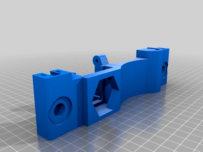
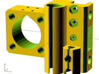
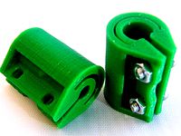
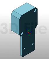
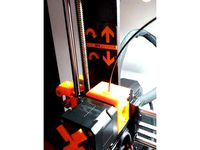
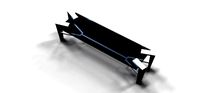
These are monolithic (single piece) Y ends that I created for prusa i3. I was inspired to try this by the Lulzbot TAZ design, and I think it's pretty neat.
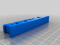
Hey everybody , I've redone both designs now in OpenSCAD to be parametric. Enjoy! The -default STL files were generated for M8 smooth rods and M10 threaded rods. If you want to roll your own, you'll need the small parts (sub assembly STLs) which are included into the single-piece models and are not meant to be printed on their own.
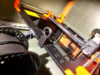
By replacing the four corner pieces plus motor and original idler mounts for the Y axis (6 printed parts) with these single-piece models, it completely eliminates the shorter M8 rods (four of them) and nuts and bolts (22 of each). Besides the elimination of vitamins, this makes the printer easier to put together at the cost of a little more plastic (both parts are approximately 100 cubic centimeters volume). The elevation and spacing of the M10 threaded rods and the M8 smooth rods has been duplicated, and the motor and idler mounts are centered to guide the belt down the middle of the frame, so these should be drop-in compatible with single-sheet frames like sgraber's. All four corners sport contoured tie-wrap guides for holding down smooth rods.
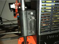
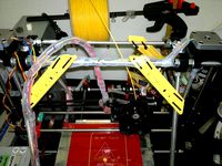
On the Motor end, a third mount was added for the stepper motor, along with a little foot for it to rest on (because stepper motors get tired). There is also a receiver slot for a 40mm fan (10mm thick). I've also added a tool-less endstop holder, which should strike the edge of the table (beneath the heated bed). It was designed to fit a 20mm x 10mm micro end stop (you'll want one that has a long throw lever).
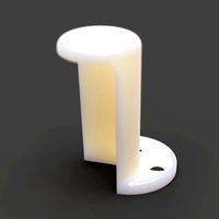
For the idler end, I wanted to keep the tensioner capability in Prusa's design so instead of fixing the idler bearings to the end piece, I created mounts that will accept the present X tensioner (yes, X). The mounts were translated a little farther back (away from the bed) so that the longer tensioner could be used, maintaining the ability to substitute different tensioners for whatever type of idler bearings you want to use. And by reusing the X tensioner, it eliminates a model from the standard build (you just make two identical X tensioners).
If you are using a laser-cut wooden frame, you'll want to attach the motor end to the rear braces of the frame (the 8mm threaded rods were previously used for this). Pick the 277mm or 235mm sized brace depending on the width (inside dimension) of your LC frame supports. The sgraber frame that I have fits the 277mm version. The braces should be put against the inside face of the motor end, between the threaded nut and the end itself. An M3 bolt and nut can be used to secure the other end of the brace to the frame itself.
Hey everybody , I've redone both designs now in OpenSCAD to be parametric. Enjoy! The -default STL files were generated for M8 smooth rods and M10 threaded rods. If you want to roll your own, you'll need the small parts (sub assembly STLs) which are included into the single-piece models and are not meant to be printed on their own.
By replacing the four corner pieces plus motor and original idler mounts for the Y axis (6 printed parts) with these single-piece models, it completely eliminates the shorter M8 rods (four of them) and nuts and bolts (22 of each). Besides the elimination of vitamins, this makes the printer easier to put together at the cost of a little more plastic (both parts are approximately 100 cubic centimeters volume). The elevation and spacing of the M10 threaded rods and the M8 smooth rods has been duplicated, and the motor and idler mounts are centered to guide the belt down the middle of the frame, so these should be drop-in compatible with single-sheet frames like sgraber's. All four corners sport contoured tie-wrap guides for holding down smooth rods.
On the Motor end, a third mount was added for the stepper motor, along with a little foot for it to rest on (because stepper motors get tired). There is also a receiver slot for a 40mm fan (10mm thick). I've also added a tool-less endstop holder, which should strike the edge of the table (beneath the heated bed). It was designed to fit a 20mm x 10mm micro end stop (you'll want one that has a long throw lever).
For the idler end, I wanted to keep the tensioner capability in Prusa's design so instead of fixing the idler bearings to the end piece, I created mounts that will accept the present X tensioner (yes, X). The mounts were translated a little farther back (away from the bed) so that the longer tensioner could be used, maintaining the ability to substitute different tensioners for whatever type of idler bearings you want to use. And by reusing the X tensioner, it eliminates a model from the standard build (you just make two identical X tensioners).
If you are using a laser-cut wooden frame, you'll want to attach the motor end to the rear braces of the frame (the 8mm threaded rods were previously used for this). Pick the 277mm or 235mm sized brace depending on the width (inside dimension) of your LC frame supports. The sgraber frame that I have fits the 277mm version. The braces should be put against the inside face of the motor end, between the threaded nut and the end itself. An M3 bolt and nut can be used to secure the other end of the brace to the frame itself.
Similar models
thingiverse
free
Parametric Prusa i3 Frame Stabilizer kit by projunk
...(2x) (back)
m10 threaded rod 394 mm (2x) (y-axis)
m10 threaded rod 385 mm (2x) (sloping)
m10 nuts (46x)
m10 washers (46x)
thingiverse
free
Prusa i3 MK2 X-Idler Tensioner by Jasenk
... kit came with extras that i used.
the pully slide (x-end-idler-front-tensioner) fits one way. if it's tight flip it around.
thingiverse
free

prusa i3 rework 1.5 alu frame brace for M10 threaded road by hygy
... long one
you need 4 pieces of m4x23mm screw + nut + washer
2 pieces of 36cm long m10 threaded rod + 8 pieces of m10 nut + washer
thingiverse
free

Prusa I3 Y-end single piece by rball716
... nuts on y-axis m8 threaded rod.
support in slic3r, 50% extrusion works.
you can also see my idler setup in the last picture
thingiverse
free

X-Axis Idler End with M10 Threads by ctchunter1
...
thing # 1118272 for the x-axis idler tensioner. this needs to be in nylon for strength.
thing # 1133926 for the x-axis carriage.
thingiverse
free

Prusa i3 Rod Clamps by oliasmage
...eet frame. it also includes a rod end you can use to mount on the lower threaded rods for bracing or to construct a spool holder.
thingiverse
free

Prusa i3 Rod Clamps by oliasmage
...eet frame. it also includes a rod end you can use to mount on the lower threaded rods for bracing or to construct a spool holder.
thingiverse
free
CR-10s Pro Frame Brace V2
...e bottom mount:
1) there are 2 screws at the corner, remove it first.
2) install the bottom mount.
3) put those 2 screws back in.
thingiverse
free
x-end motor idler for Prusa i3 with 45 mm bw rods by radus
...ler for prusa i3 with 45 mm bw rods by radus
thingiverse
x-end motor idler for prusa i3 with 45 mm between rods and m5-10mm nut
thingiverse
free
Tarantula Z-Brace for 8mm threaded rod by Toxothrix
...ner braces. lower piece is unchanged.
works with 8mm or 5/16" threaded rod. 43cm per side. i've used 8 standard m8 nuts.
Mrice
thingiverse
free
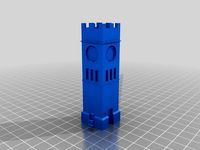
Clock Tower by mrice
...clock tower by mrice
thingiverse
this is a 1:168 scale model of the clock tower in hudson, ohio.
thingiverse
free

ATX PSU Holder by mrice
...(four pieces total), mount to deck with m4 x 20mm screws, and attach the corners on the short edges with m3 x 60mm screw and nut.
thingiverse
free

Hollow test print by mrice
...y a few grams of material to print, which makes it good for doing iterative tuning on your print settings or machine adjustments.
thingiverse
free

Panel switch by mrice
...e limit switch inside the larger housing so that the lever arm of the limit switch is against the back of the push button. easy!
thingiverse
free

LCD Keypad shield for arduino laser cut outline by mrice
...keypad shield for arduino laser cut outline by mrice
thingiverse
i made this vector outline for the 16x2 lcd with keypad shield.
thingiverse
free

Bed leveling test print by mrice
... of my bed, as i find it easier to simply observe the extruder laying down the first layer and then adjust my corners acordingly.
thingiverse
free

Wilson by mrice
...rts)
both versions are maintained in the same repository and have mostly the same parts, except for the y axis ends and brackets.
thingiverse
free
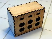
Triple Switched-Outlet project enclosure by mrice
...-outlet enclosure, with a separate toggle switch located above each outlet. the design is meant to be laser cut on 5mm material.
thingiverse
free
5mm to 8mm Z axis shaft coupler by mrice
...ible shaft couplers on z axis rods, for 5mm motor shafts and 8mm threaded rods. use two m3x10mm screws and nuts to tighten down.
thingiverse
free

Simple clothespin belt tensioner by mrice
...i'd share the technique i used.
this is how i keep tension on my wilson printer. did i mention that it is extremely cheap?
I3
3d_export
$10
suv i3
...suv i3
3dexport
suv i3 2013 series
3d_ocean
$89

BMW i3 2012
...y, in real units of measurement, qualitatively and maximally close to the original. model formats: - *.max (3ds max 2008 scanl...
cg_studio
$99

BMW i3 20143d model
...
cgstudio
.3ds .c4d .fbx .lwo .max .obj - bmw i3 2014 3d model, royalty free license available, instant download after purchase.
cg_studio
$99

BMW i3 20123d model
...tudio
.3ds .c4d .fbx .lwo .max .mb .obj - bmw i3 2012 3d model, royalty free license available, instant download after purchase.
cg_studio
$99
BMW i3 20143d model
...tudio
.3ds .c4d .fbx .lwo .max .mb .obj - bmw i3 2014 3d model, royalty free license available, instant download after purchase.
humster3d
$75
3D model of BMW i3 2014
...
buy a detailed 3d model of bmw i3 2014 in various file formats. all our 3d models were created maximally close to the original.
humster3d
$40

3D model of Kitchen Set I3
...uy a detailed 3d model of kitchen set i3 in various file formats. all our 3d models were created maximally close to the original.
3d_ocean
$30
Kitchen set i3
...ensils oven plates shelves sink table ware
kitchen set i3 include 3d models: cooker, oven, sink, cupboards, table, chair, plates.
3d_ocean
$89

BMW i3 2014
...y, in real units of measurement, qualitatively and maximally close to the original. model formats: - *.max (3ds max 2008 scanl...
cg_studio
$99

BMW i3 Concept 20113d model
...i3
.3ds .c4d .fbx .lwo .max .obj - bmw i3 concept 2011 3d model, royalty free license available, instant download after purchase.
Prusa
turbosquid
$2
Frame Filament Guide Clip-On for Prusa Mk3
...rame filament guide clip-on for prusa mk3 for download as stl on turbosquid: 3d models for games, architecture, videos. (1634730)
3d_export
free
prusa i3 mk3s laser mount for opt lasers
...to learn more about the blue laser technology that conceived the cutting and engraving laser heads from opt lasers, please visit:
turbosquid
free
Prusa small printer adapter holder
...er for download as ipt, skp, dwg, dxf, fbx, ige, obj, and stl on turbosquid: 3d models for games, architecture, videos. (1642936)
3d_export
$30

geisha by jonathan adler
...** i did a 3d printing test in the prusa software, you can find it among the attached images.<br>exchange:<br>.blend...
thingiverse
free

Prusa without Prusa (rc2) by madless
...prusa without prusa (rc2) by madless
thingiverse
just the main part of prusa rc2 faceshield, without writing.
enjoy :)
thingiverse
free
Prusa by acejbc
...prusa by acejbc
thingiverse
prusa knob info
m3 8mm screw
thingiverse
free
Prusa house
...prusa house
thingiverse
how prusa house could look like...
thingiverse
free

Prusa Mk2 "Fake Prusa" LCD cover by anraf1001
...r by anraf1001
thingiverse
version of prusa's lcd cover with "fake prusa" instead of "original prusa"
thingiverse
free
Prusa stabilizator by gutiueugen
...prusa stabilizator by gutiueugen
thingiverse
prusa stabilizator
thingiverse
free
Keychain Prusa by rbarbalho
...keychain prusa by rbarbalho
thingiverse
keychain with text prusa.
Single
3d_export
$5
single sofa single chair
...single sofa single chair
3dexport
single sofa single chair 3d model
3d_export
$5

single sofa single chair
...single sofa single chair
3dexport
single sofa single chair 3d model
3d_export
$5

single fastener
...single fastener
3dexport
single fastener
3ddd
$1
Single FLOU
... sofa , трансформер
диван-трансформер single от итальянского производителя flou
3ddd
$1
bed single
...bed single
3ddd
постельное белье
bed single 190cm*90cm
3ddd
$1

Single Flou
...single flou
3ddd
качественная моделька дивана-трансформера single flou.
3d_ocean
$9
Single sofa
...le sofa
3docean
modern sofa single sofa sofa white sofa.comfortable sofa
single sofa,sofa,modern sofa,white sofa.comfortable sofa
3d_export
free

Single Knife
...single knife
3dexport
a single knife, presumably it was used as one of the throwing knives.
3d_export
free

couch - single
...couch - single
3dexport
low poly single couch with .psd file for personal customization
3d_ocean
$5
Single Sofa
...single sofa
3docean
single sofa made by fabric , wood frame & ss leg
Ends
archibase_planet
free

Cigarettes end
...d
archibase planet
cigarettes end cigarette stub cigar-butt
cigarette-end - 3d model (*.gsm+*.3ds) for interior 3d visualization.
3d_export
$5
end table
...end table
3dexport
end table 3d model dimensions:(w)60cm×(d)60cm×(h)56cm
3d_export
$5
end table
...end table
3dexport
end table 3d model dimensions:(w)60cm×(d)60cm×(h)56cm
turbosquid
$10
End Table
...rbosquid
royalty free 3d model end table for download as max on turbosquid: 3d models for games, architecture, videos. (1570610)
turbosquid
$5
End Table
...urbosquid
royalty free 3d model end table for download as ma on turbosquid: 3d models for games, architecture, videos. (1622809)
turbosquid
$3
End Table
...rbosquid
royalty free 3d model end table for download as fbx on turbosquid: 3d models for games, architecture, videos. (1315115)
3d_export
$5

rope end ring
...rope end ring
3dexport
rope end ring
turbosquid
$2
End Tables
...
royalty free 3d model end tables for download as max and obj on turbosquid: 3d models for games, architecture, videos. (1706896)
turbosquid
$14
End Table
...lty free 3d model end table for download as max, obj, and fbx on turbosquid: 3d models for games, architecture, videos. (1403051)
turbosquid
$12
End Table
...lty free 3d model end table for download as max, obj, and fbx on turbosquid: 3d models for games, architecture, videos. (1574707)
Y
turbosquid
$1

Tetera y Galletas y Caf
... available on turbo squid, the world's leading provider of digital 3d models for visualization, films, television, and games.
3ddd
$1

Смеситель Y-CON
...смеситель y-con
3ddd
смеситель , y-con
смеситель y-con
3ddd
$1
Y-Chair
...y-chair
3ddd
tom dixon
y-chair designed by tom dixon,
3ds max + obj, corona
3ddd
$1
Y Chair compilation
....net/products/us/y-chair-sled-base
y chair swivel basehttp://www.tomdixon.net/products/us/y-chair-swivel-base
turbosquid
$190
Y-8
...y-8
turbosquid
royalty free 3d model y-8 for download as max on turbosquid: 3d models for games, architecture, videos. (1658891)
turbosquid
$7
Bench Y
...turbosquid
royalty free 3d model bench y for download as obj on turbosquid: 3d models for games, architecture, videos. (1488746)
turbosquid
$15

bonePile Y
...oyalty free 3d model bonepile y for download as blend and obj on turbosquid: 3d models for games, architecture, videos. (1546374)
turbosquid
$7

Y for Yarn
...d
royalty free 3d model y for yarn model for download as max on turbosquid: 3d models for games, architecture, videos. (1699732)
turbosquid
$2
FONT Y
...quid
royalty free 3d model font y for download as ma and obj on turbosquid: 3d models for games, architecture, videos. (1549457)
3ddd
$1

WOOD-y
...wood-y
3ddd
wooden guy
Piece
archibase_planet
free

Piece
...piece
archibase planet
sand-box playground
piece 8 - 3d model (*.gsm+*.3ds) for interior 3d visualization.
archibase_planet
free

Piece
...piece
archibase planet
smithy forge farriery
piece 12 - 3d model (*.gsm+*.3ds) for interior 3d visualization.
turbosquid
$7

piece
...turbosquid
royalty free 3d model piece for download as sldpr on turbosquid: 3d models for games, architecture, videos. (1407696)
archibase_planet
free

Piece
...piece
archibase planet
merry-go-round roundabout carrousel
piece 5 - 3d model (*.gsm+*.3ds) for interior 3d visualization.
3d_export
free

Lego piece
...lego piece
3dexport
lego piece<br>.stl
turbosquid
free

Chess Pieces
...es
turbosquid
free 3d model chess pieces for download as fbx on turbosquid: 3d models for games, architecture, videos. (1502330)
turbosquid
$5

Skywalk Piece
...quid
royalty free 3d model skywalk piece for download as max on turbosquid: 3d models for games, architecture, videos. (1422588)
turbosquid
$1

chess pieces
...squid
royalty free 3d model chess pieces for download as obj on turbosquid: 3d models for games, architecture, videos. (1562332)
turbosquid
$1

chess piece
...osquid
royalty free 3d model chess piece for download as fbx on turbosquid: 3d models for games, architecture, videos. (1369649)
turbosquid
free

Chess Pieces
...uid
royalty free 3d model chess pieces for download as blend on turbosquid: 3d models for games, architecture, videos. (1323069)