Thingiverse
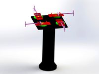
Single gang mounting system for RaspberryPi with Touchscreen by kevinkahn
by Thingiverse
Last crawled date: 3 years ago
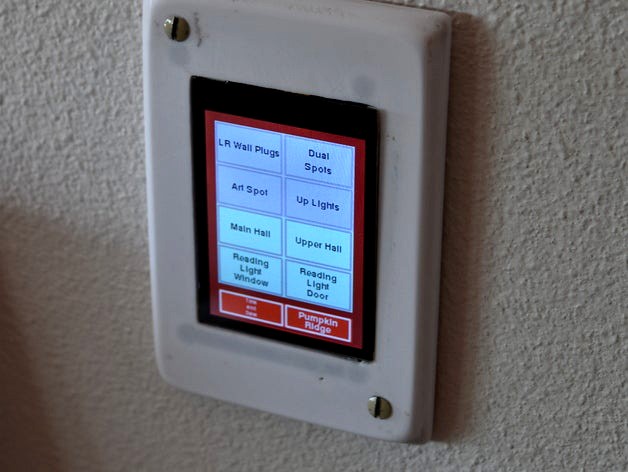
This set of parts allows the mounting of a Raspberry Pi 0 with an Adafruit 2.8" Touchscreen (model 2423 or 2298) into a single gang wall box with room for an Insteon micro on/off or dimmer. There are 2 versions - one meant to print outer face down and the other outer face up. To print the first of these without awful support that screw holes for mounting the faceplate are done as separate inserts. The space for the micro switch and a tiny hole in the faceplate allow one to use a small paper clip to do a power reset on the Pi so that it can be restarted if needed without cycling a circuit breaker. For a discussion of the software I am using with this and related items see: http://forum.universal-devices.com/topic/18026-soft-keypadlinc-like-console-from-raspberry-pi/ and http://forum.universal-devices.com/topic/19124-wall-mount-rpi-with-28-touchscreen/
Rev2: faceplateV9 is an improved faceplate with better thinning on the back for protrusions of the PiTFT. Printing the faceplate face down will yield a great smooth finish on the large flat part but in my experience pretty marginal side curves. Printing it face up, while a bit counter-intuitive yields pretty good flat part and great sides. Sanding out the flat part down to 800 grit or better will then yield a very nice result, particularly if, like me, you need to paint it to match commercial plates nearby (mine needed to be ivory).
Assembly notes:
After answering various questions in the UDI forum about how this gets assembled I thought it was worthwhile to summarize some of the info here. The Pi0 gets mounted to the display using a straight through header that needs to be soldered to it on the component side of the board. It then plugs directly into the bottom of the display. The power supply that this is designed for is a Hi-Link PM01 (e.g., https://www.amazon.com/Hi-link-HLK-PM01-Step-Down-Intelligent-Household/dp/B01B7G6LYE) available for $3 or less on Amazon, ebay, etc. It also uses a standard microswitch to allow power reset of the Linux system without pulling the breaker. The output of the power supply is wired through the microswitch with jumpers to the usb power port of the Pi0. I used a micro usb OTG adapter like this one: https://www.adafruit.com/products/2910 (also available on ebay etc.) with the power and ground jumpers soldered to the outside pins (power/+5 to pin1 and ground/-5 to pin4). This allows easier assembly than soldering power directly to the Pi0 board power pads. I also use a micro WiFi adapter in the Pi0 USB port. I used heat shrink over all exposed wires. An Insteon micro on/off or dimmer fits on the lower shelf if desired to control a local load. It should go without saying that this is NOT UL approved. Having said that the design does keep the 120v to below the horizontal bulkhead with the exception of the soldering of the 120v input to the power supply. This should physically separate the 120 and 5 volt parts of the design. Use at your own risk.
Similar models
thingiverse
free

E3 Front Mount Pi 3 B+ Enclosure by BlakeCary
...mount pi 3 b+ enclosure by blakecary
thingiverse
modified to allow micro usb power with lm2596 and added a 25mm fan to the face.
thingiverse
free

Enclosure for Duet 3 mini with Raspberry Pi 7i touchscreen by nikscha
...ps://forum.duet3d.com/topic/22752/can-i-power-a-rpi4-from-the-duet-3-mini/7)
air is directed underneath the duet and out the side
thingiverse
free

Retro Playstation Pi Micro USB Power Outlet by jakobwesthoff
...verter from this project.
additional parts
i used the following micro-usb cable as inlay for this part:
startech 0,5 m, micro-usb
thingiverse
free

1U Pie Rack by commanderbeatle2
...m/gp/product/b00j3mhtyg/ref=oh_aui_detailpage_o02_s00?ie=utf8&psc=1
micro usb breakouthttps://www.sparkfun.com/products/10031
thingiverse
free

MacPi v2.1 remixed pieces for DC power jack by ApplesUPnorth
...mount was slimmed down and stand offs lowered to allow the raspi-z to be mounted farther left, so there was room for the dc jack.
thingiverse
free

Raspberry Pi Touchscreen Stand with Gap by mkellner
...so i openscad'd a gap in the stand which allows me to put a small usb cable to power the pi from the touchscreen logic board.
3dwarehouse
free

Hi-link HLK-PM01 220V - 5v power supply module
...hi-link hlk-pm01 220v - 5v power supply module
3dwarehouse
hi-link hlk-pm01 5v power supply module electronic component
thingiverse
free

Prusa i3 Mk2 Mount for Pi Zero W with tiny Camera by ra100
...
added small hinge for better fit and stability of pi0
added hole, so pi0 can be used upside down, and still have pins accessible
thingiverse
free

Atari XL/XE USB Power Adapter Box by piep3d
...-bit computers and solder to a micro-usb connector. salvage the nameplate off the power supply and decorate the boring black box.
thingiverse
free

4-port USB Car Charger Power Supply Step-Down Module (Buck) by Haddenja
...er i use to power my raspberry pi 3.
i want to add a stand/mount and a desk top version. i will post updates when i get it done.
Kevinkahn
thingiverse
free

Snap connector by kevinkahn
...s to connect more solid things. since this is of no value unless incorporated in a larger design i have included the 123dx file.
thingiverse
free

3D Print Removal Tool Handle by kevinkahn
.... printed at .3 with 4 top and bottom layers and 4 perimeters to provide a solid slot for the handle that would stand up to use.
thingiverse
free

Clicgear Holder for Large Sand Bottle by kevinkahn
... the lockbar secures them together. the pin is forms the hinge and the hingepinlock insures the hinge pin doesn't slide out.
thingiverse
free

Sand Bottle Holder for Clickgear Golf Cart by kevinkahn
...le with no problems. the picture also shows the assembly - all the pins are press fit and the design requires no other hardware.
thingiverse
free
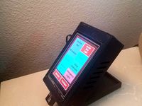
Bedside Raspberry Pi Console Case for 3.5" PiTFT by kevinkahn
...ck of the case. the hinge is a simple press fit. the prop can be adjusted forward and back in the slot to get the tilt desired.
thingiverse
free

FlashForge Creator Pro 2016 Tool Hanging System (Qidi too) by kevinkahn
...ess clips to lock the hanger to the rail. the bin just lifts off to empty.
added a slightly longer rail that fits qidi printers.
Raspberrypi
thingiverse
free

board on the Raspberrypi by bacon0817
...board on the raspberrypi by bacon0817
thingiverse
mount the rgboard on the raspberrypi
thingiverse
free

RaspberryPi Rack by imagifab
...raspberrypi rack by imagifab
thingiverse
simple rack to keep a raspberrypi off of a workstation.
thingiverse
free

RaspberryPi 3B+ Case
...raspberrypi 3b+ case
thingiverse
this is a case for raspberrypi 3b+. the covers are snap fit. you can choose from two covers.
thingiverse
free

SBC Case-RaspberryPi by XSHELL
...sbc case-raspberrypi by xshell
thingiverse
raspberrypi case designed by xshell inc.
thingiverse
free

Raspberrypi logo by dpruim
...errypi logo with openscad source
i used it as ornament on my case..
and there are 8 spacers in there as well that i needed. . .
thingiverse
free

RaspberryPi 3 case with ender logo by freddysphoto
...perfectly.
raspberrypi 3: works perfectly.
raspberrypi 2: should fit. feedback?
raspberrypi b+: community reported that it works.
thingiverse
free
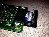
RaspberryPi SDCard retainer by IndianaTux
...en if the raspberrypi is subjected to vibration.
as always source available on my github: https://github.com/netforces/hardware
thingiverse
free

RaspberryPI 1Bp 2 and 3
...raspberrypi 1bp 2 and 3
thingiverse
raspberrypi 1b+ 2 and 3
with sd card added.
and real ethernet, real usb,
thingiverse
free

SSD - RaspberryPI case by cgerrist
...ypi case by cgerrist
thingiverse
a little case for a ssd and raspberrypi 3
together it is my personal nas with a mysql database.
thingiverse
free

RaspberryPi stand by Schorhr
...raspberrypi stand by schorhr
thingiverse
moep.
sick & bored.
Gang
3d_export
$25
jin gang
...jin gang
3dexport
simple rendering of the scene file
3ddd
$1

Чайный сервиз Gange
... armani casa , сервиз
чайный сервиз gange, armani casa (италия)
turbosquid
$30

29-Duplex plate set 1 gang to 6 gang and materials
... available on turbo squid, the world's leading provider of digital 3d models for visualization, films, television, and games.
turbosquid
$32

Gang Construction Conveyor
...ree 3d model gang construction - conveyor for download as max on turbosquid: 3d models for games, architecture, videos. (1452373)
turbosquid
$119

Cartoon Faces Gang
... available on turbo squid, the world's leading provider of digital 3d models for visualization, films, television, and games.
turbosquid
$41

South Park Gang
... available on turbo squid, the world's leading provider of digital 3d models for visualization, films, television, and games.
turbosquid
$25
Swivel vice gang
... available on turbo squid, the world's leading provider of digital 3d models for visualization, films, television, and games.
turbosquid
$32

Gang Building - Primary Room
...ree 3d model gang building - primary room for download as max on turbosquid: 3d models for games, architecture, videos. (1452370)
turbosquid
$32

Gang Construction - Wood Shelf
...e 3d model gang construction - wood shelf for download as max on turbosquid: 3d models for games, architecture, videos. (1452380)
turbosquid
$32

Gang Construction - Arrow Tower
... 3d model gang construction - arrow tower for download as max on turbosquid: 3d models for games, architecture, videos. (1452378)
Touchscreen
3d_ocean
$10

Touchscreen Phone
...r stand alone renderings. the button as well as speaker on the front are modelled for added realism and depth for those tight ...
turbosquid
$2

Touchscreen Kiosk
... available on turbo squid, the world's leading provider of digital 3d models for visualization, films, television, and games.
3d_export
$35
TF 700 Tablet PC 10 in touchscreen 3D Model
...export
universal tablet pc 10 in touchscreen android notebook
tf 700 tablet pc 10 in touchscreen 3d model plasticv 80776 3dexport
3d_ocean
$10

Sleek Touchscreen Smart Phone
... of multi-touch smart phone designs. the small details such as the buttons, camera lens, speaker and other components have bee...
3ddd
$1

Celular Samsung
...3ddd телефон , samsung samsung s5230 mid level full touchscreen ...
3d_export
$30
LG arena 3D Model
...arena 3d model 3dexport lg km900 arena phone mobile touchscreen lg arena 3d model s.e.3ddd 26566...
3d_export
$30

SONY Xperia Tablet 3D Model
...xperia tablet 3d model 3dexport sony xperia tablet android touchscreen sony xperia tablet 3d model barbarosa222 58716...
3d_export
$15
Iphone Black 3D Model
...black 3d model 3dexport phone electronics iphone cellphone smartphone touchscreen touch screen iphone black 3d model ryleyswan 81168...
3d_export
$40

Google Nexus One 3D Model
...3d model 3dexport google nexus one phone mobile cellular touchscreen google nexus one 3d model h1studio 21421...
3d_export
$45
HTC Flyer Tablet 3D Model
...htc flyer tablet 3d model 3dexport touchscreen tablet htc 3d model 3ds max phone htc flyer...
Single
3d_export
$5

single sofa single chair
...single sofa single chair
3dexport
single sofa single chair 3d model
3d_export
$5

single sofa single chair
...single sofa single chair
3dexport
single sofa single chair 3d model
3d_export
$5

single fastener
...single fastener
3dexport
single fastener
3ddd
$1
Single FLOU
... sofa , трансформер
диван-трансформер single от итальянского производителя flou
3ddd
$1
bed single
...bed single
3ddd
постельное белье
bed single 190cm*90cm
3ddd
$1

Single Flou
...single flou
3ddd
качественная моделька дивана-трансформера single flou.
3d_ocean
$9
Single sofa
...le sofa
3docean
modern sofa single sofa sofa white sofa.comfortable sofa
single sofa,sofa,modern sofa,white sofa.comfortable sofa
3d_export
free

Single Knife
...single knife
3dexport
a single knife, presumably it was used as one of the throwing knives.
3d_export
free

couch - single
...couch - single
3dexport
low poly single couch with .psd file for personal customization
3d_ocean
$5
Single Sofa
...single sofa
3docean
single sofa made by fabric , wood frame & ss leg
System
archibase_planet
free
System
...m
archibase planet
fire alarm system fire alarm box
security light system - 3d model (*.gsm+*.3ds) for interior 3d visualization.
archibase_planet
free
Spider system
...stem spider glass system
spider system to fix glass stefano galli n050912 - 3d model (*.gsm+*.3ds) for interior 3d visualization.
3ddd
$1

Euforia System
...euforia system
3ddd
euforia
euforia system
3d_export
$50
Roof system Truss system 3D Model
...oof system truss system 3d model
3dexport
roof system truss truss stage
roof system truss system 3d model aleksbel 38970 3dexport
3ddd
$1
DVD System
...dvd system
3ddd
dvd , schneider
dvd system
design_connected
free
Seating system
...seating system
designconnected
free 3d model of seating system
3d_export
$5

solar system
...solar system
3dexport
solar system in c4d, with 8k nasa textures
3ddd
$1
Quanta System
...quanta system
3ddd
медицина
quanta system.
лазерное оборудование для медицинских центров
3d_export
$15
solar system
...nd the other the sun, the earth and the moon, the latter has an animation with camera movement included, the files are in spanish
3d_export
$14

missile system
...missile system
3dexport
Mounting
3d_export
free

mounting bracket
...mounting plate is the portion of a hinge that attaches to the wood. mounting plates can be used indoors, cabinetry and furniture.
turbosquid
$2

MOUNTING
... available on turbo squid, the world's leading provider of digital 3d models for visualization, films, television, and games.
turbosquid
free

Mounts
... available on turbo squid, the world's leading provider of digital 3d models for visualization, films, television, and games.
turbosquid
free

Mount Fuji
...fuji
turbosquid
free 3d model mount fuji for download as obj on turbosquid: 3d models for games, architecture, videos. (1579977)
3d_export
$5

Headphone mount LR
...headphone mount lr
3dexport
headphone mount l+r
turbosquid
$39

Mount rainier
...quid
royalty free 3d model mount rainier for download as fbx on turbosquid: 3d models for games, architecture, videos. (1492586)
turbosquid
$5

pipe mounting
...quid
royalty free 3d model pipe mounting for download as obj on turbosquid: 3d models for games, architecture, videos. (1293744)
turbosquid
$3

Mounting Tires
...uid
royalty free 3d model mounting tires for download as fbx on turbosquid: 3d models for games, architecture, videos. (1708511)
3d_export
$5

Magnetic GoPro Mount
...pro mount
3dexport
cool magnetic mount for gopro. allows you to mount the camera on flat metal surfaces and get exclusive shots.
turbosquid
$5

Stone Mount
...ty free 3d model stone mount for download as ma, obj, and fbx on turbosquid: 3d models for games, architecture, videos. (1370306)