Thingiverse
Simple Door Lock - 3D-Printing and Arduino Project by Caverntwo
by Thingiverse
Last crawled date: 3 years ago
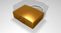
Simple Door Lock - A 3D-Printing and Arduino Project
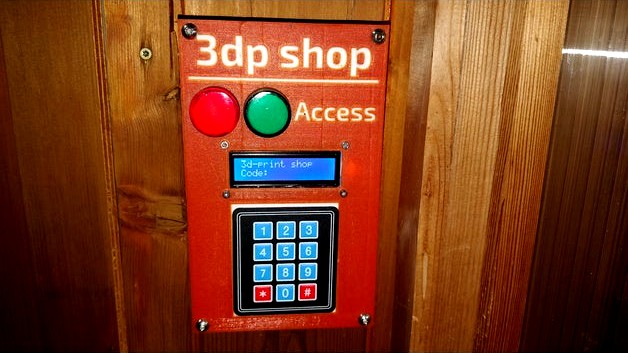
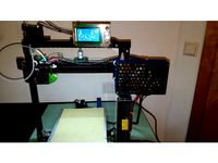
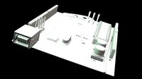
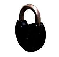
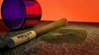
This door lock is the ultimate solution to the very professional way of keeping the door to the 3d-print shop shut (which didn't work well BTW.) seen in the last image.
Actually, an electric door lock was installed before but there was an issue with the controller, rendering it more or less useless...
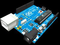
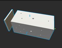
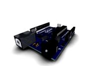
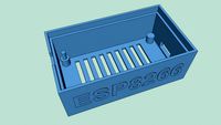
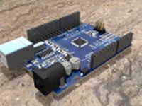
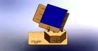
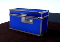
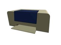
The project consists of two main parts, namely the outdoor door terminal and the indoor electronics enclosure. I used an Arduino Uno as the controller, however, it works with others as well.
Make sure to check out the [accompanying video] of this project for more information!
Important
For now, I only publish the dual-color outer terminal cover, and the multi-colored model for single extruder machines is still WIP!
BOM
These are the parts that I used:
Electronics
1x Arduino Uno
1x LCD 1602 with I2C adapter
1x 1A fuse with DIN-rail holder
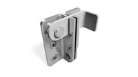
1x door lock 12v
1x PSU 12V 10A (to be mounted externally)
1x Indicator Red 12V
1x Indicator Green 12V
2x 5V Relay Module
Printed parts
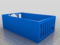
Electronics enclosure base
Electronics enclosure cover
Door terminal base
Door terminal cover
Miscellaneous
Pinheads and sockets or DuPont connectors
0.14 and 0.25mm wires
Ferrules for screwed wire connections
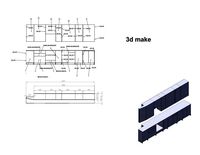
Printed Parts
The printed parts in this thing are just the outside terminal and the inner enclosure. It doesn't include the DIN rail and holders for the inner enclosure.
Here are links to the mentioned parts:
DIN rail: print one of the many available designs
Arduino Holder:https://www.thingiverse.com/thing:500504
Relay Holder: https://www.thingiverse.com/thing:3001457
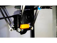
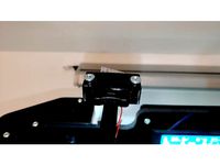
The inner enclosure can be printed in PLA while the outer enclosure has to be printed in PETG, ABS, ... to avoid bending/melting like seen here and here.
Assembly
The assembly takes longer than you might expect, be aware of that!
Print all parts and get everything ready
Connect the 5V part according to the schematics (blue wires, see below). Either solder the wires to the pinheads and sockets (like I did) or use DuPont connectors. You need to be able to quickly disassemble/reassemble it later on when you install it. Also, it's better to have the wires too long than too short, as you need to pull them thru the wall!
Test it out. Don't forget to upload the firmware (see below).
If everything is fine so far, go on with the 12V part (black in the schematics). The Arduino's power is supplied with the 12V attached to the VIN (+) and GND (-) pins.
Take a good look over your circuit. Is it safe? Use common sense! Double-check everything. Then supply 12V using a PSU and test it out.
Alright, it's working fine, now, remove all power and start installing it into the cases. You might need to disassemble some parts.
Use some silicone to make the LCD screen waterproof.
If you encounter any difficulties or stuff that is unclear to you, just comment me!
This door lock is the ultimate solution to the very professional way of keeping the door to the 3d-print shop shut (which didn't work well BTW.) seen in the last image.
Actually, an electric door lock was installed before but there was an issue with the controller, rendering it more or less useless...
The project consists of two main parts, namely the outdoor door terminal and the indoor electronics enclosure. I used an Arduino Uno as the controller, however, it works with others as well.
Make sure to check out the [accompanying video] of this project for more information!
Important
For now, I only publish the dual-color outer terminal cover, and the multi-colored model for single extruder machines is still WIP!
BOM
These are the parts that I used:
Electronics
1x Arduino Uno
1x LCD 1602 with I2C adapter
1x 1A fuse with DIN-rail holder
1x door lock 12v
1x PSU 12V 10A (to be mounted externally)
1x Indicator Red 12V
1x Indicator Green 12V
2x 5V Relay Module
Printed parts
Electronics enclosure base
Electronics enclosure cover
Door terminal base
Door terminal cover
Miscellaneous
Pinheads and sockets or DuPont connectors
0.14 and 0.25mm wires
Ferrules for screwed wire connections
Printed Parts
The printed parts in this thing are just the outside terminal and the inner enclosure. It doesn't include the DIN rail and holders for the inner enclosure.
Here are links to the mentioned parts:
DIN rail: print one of the many available designs
Arduino Holder:https://www.thingiverse.com/thing:500504
Relay Holder: https://www.thingiverse.com/thing:3001457
The inner enclosure can be printed in PLA while the outer enclosure has to be printed in PETG, ABS, ... to avoid bending/melting like seen here and here.
Assembly
The assembly takes longer than you might expect, be aware of that!
Print all parts and get everything ready
Connect the 5V part according to the schematics (blue wires, see below). Either solder the wires to the pinheads and sockets (like I did) or use DuPont connectors. You need to be able to quickly disassemble/reassemble it later on when you install it. Also, it's better to have the wires too long than too short, as you need to pull them thru the wall!
Test it out. Don't forget to upload the firmware (see below).
If everything is fine so far, go on with the 12V part (black in the schematics). The Arduino's power is supplied with the 12V attached to the VIN (+) and GND (-) pins.
Take a good look over your circuit. Is it safe? Use common sense! Double-check everything. Then supply 12V using a PSU and test it out.
Alright, it's working fine, now, remove all power and start installing it into the cases. You might need to disassemble some parts.
Use some silicone to make the LCD screen waterproof.
If you encounter any difficulties or stuff that is unclear to you, just comment me!
Similar models
thingiverse
free

DIN Rail Screw Held Terminal Block by Atomist
...nc connect connection connector connectors electronics screw terminal_block terminal_strip wire wires wire_holder wire_management
grabcad
free

Enclosure design for Door locking security system (Arduino Uno & RFID)
... your enclosure design
website:- https://www.skw.lk/
linkedin: https://www.linkedin.com/company/sketch-work
email:- info@skw.lk
thingiverse
free

Raspberry Pi & Electronics Control Case by E_Raw
... gnd) and manage properly:
2x pwn 120mm fans
1x neopixel 60 ledss strip (rgb)
4x relay ports
3x 1-wire ds18b20 temperature probes
3dwarehouse
free

wiring contact for din rail
...ust a simple wiring terminal for use on a din rail. in the style of phoenix contact. #block #contact #din #rail #terminal #wiring
thingiverse
free
DIN rail for arduino UNO + 8 relay board by patriciokeogan
... model for 3d printing for a din rail mount.
arduino uno and 8 relay module in this 3d model were downloaded from grabcad.
enjoy!
thingiverse
free
Entrance system by marigu
...ll and arduino knows that lock is opened(relay is connected as simple button to arduino).
printer:
prusa i3 mk3
20 infill
0.2
pla
grabcad
free

DIN rail mount for arduino UNO + 8 relay module
...3d printing for a din rail mount.
arduino uno and 8 relay module in this 3d model were downloaded also from this website.
enjoy!
thingiverse
free

PSU And Relay Enclosure by Brenne
...bber seal, it helped bringing noise down and temperatures up. the frame can easily be disassembled by opening four plastic locks.
grabcad
free

Arduino UNO Rail Mounting Enclosure
...arduino uno rail mounting enclosure
grabcad
arduino uno rail mounting enclosure
din rail top hat
thingiverse
free
Temperature controller box for 3d printer enclosure by Omdoyas
...,0-40v
1x arduino nano
1x ds18b20 temperature probe
1x noctua nf-a4x20 flx
1x noctua nf-a8 flx
m3 screws to mount the electronics
Caverntwo
thingiverse
free

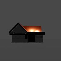
Minecraft Village House by Caverntwo
...
i've created a video about the process used for creating this model, check it out: https://youtu.be/ktkemkvs_gs
have fun ;-)
thingiverse
free

TronXY X1 Extruder Motor Holder by Caverntwo
...at the filament touches the z-axis leadscrew, i chose this position because i haven't used the original handle a single time.
thingiverse
free

Anet A8 Simple Switch Holder by Caverntwo
...ing-mts-202-mini-toggle-switch-on-on-6p-mts202/32331052163.html
just print this part, solder the wires and screw it on. have fun!
thingiverse
free
Anycubic Kossel Fan Adapter by Caverntwo
...an+50mm
the design uses two of the original screws.
see my thoughts about the anycubic kossel here: https://youtu.be/2wpbzrkixtc
thingiverse
free
Anet A8 SD-Extension Holder by Caverntwo
...//www.thingiverse.com/thing:2520383)
sd-extender cable (https://www.aliexpress.com/wholesale?searchtext=micro+sd+extension+cable)
thingiverse
free

Simple PSU Box by Caverntwo
...liexpress.com/item/red-light-power-rocker-switch-fused-iec-320-c14-inlet-power-socket-fuse-switch-connector-plug/32679674596.html
thingiverse
free

2020 NEMA 17 Motor Holder by Caverntwo
...frame of the printer using a basic plastic bracket.
therefore i quickly designed this model to still be able to finish the build.
thingiverse
free

Anycubic Kossel PSU Box by Caverntwo
...crews for mounting the psu
4x ≥8mm m3 screws for the cover (the nut spaces are normally not needed)
1x power inlet, like this one
thingiverse
free

Relay Module DIN-Rail Holder by Caverntwo
.....
i have printed and used this design multiple times, and it always worked.
if it doesn't for you, make sure to let me know!
thingiverse
free
Anet A2 - Electronics & MOSFET Case by Caverntwo
...mend this psu case, as it mounts the device firmly, with no loose wires!
check out my upgrade video: https://youtu.be/celzjblpkp8
Arduino
turbosquid
$7
Arduino
...turbosquid
royalty free 3d model arduino for download as max on turbosquid: 3d models for games, architecture, videos. (1197165)
turbosquid
$3
Arduino
...turbosquid
royalty free 3d model arduino for download as c4d on turbosquid: 3d models for games, architecture, videos. (1305484)
3d_export
$5
arduino satellite
...rt
this model is the exact arduino based satellite model with some basic sensors and camera modules and also includes batteries.
turbosquid
$1
Arduino UNO
...alty free 3d model arduino uno for download as , stl, and wrl on turbosquid: 3d models for games, architecture, videos. (1515932)
3d_export
$5
esp8266 box arduino
...esp8266 box arduino
3dexport
box for esp8266 module with wire hole. inside dimensions: 49x26 mm. height 15 mm.
3d_export
$60
Arduino Uno Rev3 Microcontroller 3D Model
...mega328p circuit board spark cable wire 5v 74v 9v 111v
arduino uno rev3 microcontroller 3d model danielgarnier4403 97237 3dexport
3d_export
free
arduino rover kit
...no!!! materials: no!!! rigged: no animated: no uv mapped: no it is not an exact copy of the original! not subject to 3d printing!
3d_ocean
$7
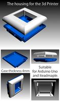
The housing for the 3d Printer
...the housing for the 3d printer 3docean arduino device housing stl the housing consists of two portions:...
3d_export
$5
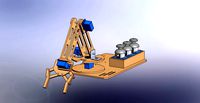
arm 4 axis
...uno -4 servo motor 180° -3 joystick (x,y) for arduino -mdf wood -some wires -cnc laser cut...
3d_export
$5
solar tracker
...machine for the frame . list of material : -arduino uno -2 step motor with driver -4 ldr sensor...
Lock
turbosquid
$1

Lock
...ck
turbosquid
royalty free 3d model lock for download as fbx on turbosquid: 3d models for games, architecture, videos. (1286851)
3d_export
$5

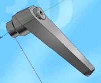
lock handle
...lock handle
3dexport
lock handle
3d_export
$5
hinged lock
...hinged lock
3dexport
hinged lock
turbosquid
$1
Lock Box with combination lock
...ee 3d model lock box for download as 3ds, obj, fbx, and blend on turbosquid: 3d models for games, architecture, videos. (1215494)
turbosquid
$2
Lock
...
royalty free 3d model lock for download as max, obj, and fbx on turbosquid: 3d models for games, architecture, videos. (1452660)
turbosquid
$35

Lock
... available on turbo squid, the world's leading provider of digital 3d models for visualization, films, television, and games.
turbosquid
$24

lock
... available on turbo squid, the world's leading provider of digital 3d models for visualization, films, television, and games.
turbosquid
$10

Lock
... available on turbo squid, the world's leading provider of digital 3d models for visualization, films, television, and games.
turbosquid
$6

Lock
... available on turbo squid, the world's leading provider of digital 3d models for visualization, films, television, and games.
turbosquid
$4
Lock
... available on turbo squid, the world's leading provider of digital 3d models for visualization, films, television, and games.
Door
3d_export
$5
door handle of doors
...door handle of doors
3dexport
door handle of doors
3d_ocean
$4

Door
...3docean
architecture door gate gothic door old style door
door, 3d door, gothic door, architecture, old style door, gate, 3d gate
3d_ocean
$10

Door
...door
3docean
design door doors home house indoor interior opening doors
door design
archibase_planet
free
Door
...r
archibase planet
door sliding door interior door rail door
door n250515 - 3d model (*.gsm+*.3ds) for interior 3d visualization.
archibase_planet
free
Door
...door
archibase planet
door sash door sash-door interior door
door 900 - 3d model (*.gsm+*.3ds) for interior 3d visualization.
archibase_planet
free
Door
...door
archibase planet
door sash door sash-door interior door
door 600 - 3d model (*.gsm+*.3ds) for interior 3d visualization.
archibase_planet
free
Door
...door
archibase planet
door sash door sash-door interior door
door 800 - 3d model (*.gsm+*.3ds) for interior 3d visualization.
archibase_planet
free
Door
...door
archibase planet
door sash door sash-door interior door
door 800 - 3d model (*.gsm+*.3ds) for interior 3d visualization.
archibase_planet
free
Door
...door
archibase planet
door sash door sash-door interior door
door 700 - 3d model (*.gsm+*.3ds) for interior 3d visualization.
archibase_planet
free
Door
...door
archibase planet
door sash door sash-door interior door
door 600 - 3d model (*.gsm+*.3ds) for interior 3d visualization.
Project
3d_export
$7
project
...project
3dexport
project
3d_export
$20
Project
...project
3dexport
design_connected
$16

Project Chair
...project chair
designconnected
rex kralj project chair computer generated 3d model. designed by žitnik, marjan.
3ddd
$1
lectric Project
...настроены. сетка очень плотная.
доступно только для группы "profi"
про группу "profi" можно прочитать в чаво
3d_ocean
$19

Soon project
...kup. made in 3ds max 2013 1- 3dsmax with vray render included material and light 2- obj file 3- fbx file hope you like it plea...
turbosquid
$49
Joint | Project
...squid
royalty free 3d model joint | project for download as on turbosquid: 3d models for games, architecture, videos. (1297983)
turbosquid
$11
house project
...bosquid
royalty free 3d model house project for download as on turbosquid: 3d models for games, architecture, videos. (1672482)
turbosquid
$450
University project
...
royalty free 3d model university project for download as rvt on turbosquid: 3d models for games, architecture, videos. (1463354)
turbosquid
$30
smart projecter
...lty free 3d model smart projecter for download as max and obj on turbosquid: 3d models for games, architecture, videos. (1236214)
3d_export
$5
project drawing
...project drawing
3dexport
project drawing and 3d model<br>format jpg sldprt dwg<br>by 3d make
Simple
turbosquid
$1

Simple goblet (Taca simples)
... available on turbo squid, the world's leading provider of digital 3d models for visualization, films, television, and games.
3d_export
$5
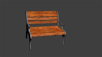
simple bench
...simple bench
3dexport
the simple bench which can be used in simple projects or video-games.
3d_export
$5
simple knob
...simple knob
3dexport
simple knob
3d_export
$5
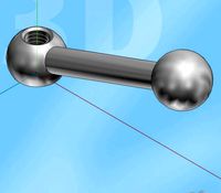
simple handle
...simple handle
3dexport
simple handle
3d_export
$5
simple button
...simple button
3dexport
simple button
3d_export
$5
simple spindle
...simple spindle
3dexport
simple spindle
3d_export
$5

simple wheel
...simple wheel
3dexport
simple wheel
3d_export
$5
simple chair
...simple chair
3dexport
simple blue chair
3d_export
free
Simple room
...simple room
3dexport
here is a simple but beautiful room
3ddd
free

SIMPLE | Кресло
...io cianfarra , simple
производитель area declic дизайн giulio cianfarra коллекция simple
Printing
design_connected
$27
...print
designconnected
moroso print computer generated 3d model. designed by wanders, marcel.
3ddd
free

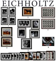
Eichholtz Prints
...- eichholtz print central station i
13 - eichholtz print central station ii
14 - eichholtz print marisa
15 - eichholtz print tish
3ddd
$1

Eichholtz Prints
...print abstract - set of 2
10 - eichholtz print orange abstract
11 - eichholtz print buddha right
12 - eichholtz print buddha left
turbosquid
$1
... available on turbo squid, the world's leading provider of digital 3d models for visualization, films, television, and games.
3ddd
free
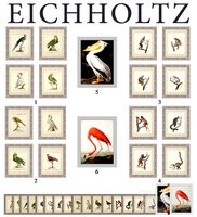
Eichholtz Prints
...of 4
2 - print dunbar 2 set of 4
3 - print guadeloupe 1 set of 4
4 - print guadeloupe 2 set of 4
5 - print giles
6 - print trett
3ddd
$1
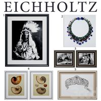
Eichholtz Prints
...nt tutti frutti
3 - eichholtz prints watson - set of 2
4 - eichholtz prints antique nautilus - set of 2
5 - eichholtz print tiara
3d_export
$5
Monster for printing
...monster for printing
3dexport
monster 3d model printing
3ddd
free
printed rug
...printed rug
3ddd
ковер
very creative printed rug
3ddd
free
Eichholtz Prints
...иал: бумага
габариты (вхш): 72 x 62 см
описание: print sweetmeat - постер в деревянной раме.
3 - prints varsity set of 2
арти
3ddd
free
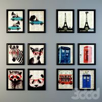
Art Print Posters
...art print posters
3ddd
прованс
art print posters by patrician prints