Thingiverse
Simple Automatic Fish Feeder by bicx
by Thingiverse
Last crawled date: 3 years ago
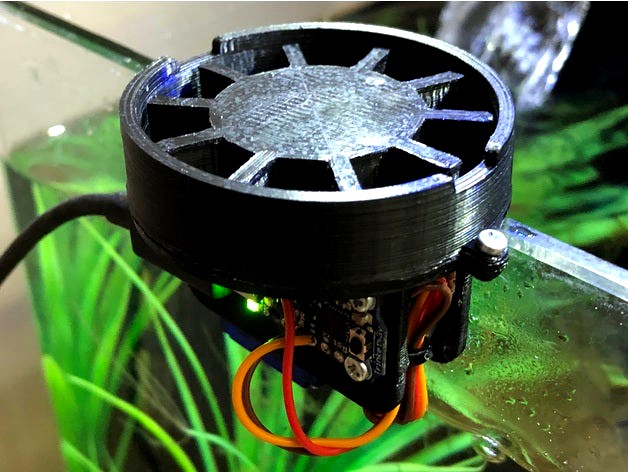
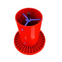
This is a simple automatic fish feeder built using some cheap components I originally had lying around from previous projects. This design works well with food pellets, but feel free to try it with other forms of food. The feeder should be a perfect fit for aquariums with rimless 4mm glass walls. If you have this 5-gallon aquarium like I do, you should be golden.
(Demo video: https://youtu.be/mi4jcUzdbd0)
Servo
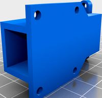
The center slot is designed to friction-fit an SG90 servo that spins the food rotor, but I would recommend some sort of extra anchoring (I used hot glue since it can be removed). As far as servos go, I had the 180-degree-limited servo left over from my first Arduino Uno kit from Vilros. To convert it to a continuous servo, I performed some modifications. However, if you can spare $7.50, just get the purpose-made continuous servo in the same form factor. The final modification you need to make for this project is to cut a 1mm-wide and 2mm-deep slot into the servo's nylon gear connector in order to connect to the feed rotor. I just used an Xacto blade. This isn't ideal, but it allows for decent leverage. Before permanently affixing your servo, do a test run with your rotor to make sure everything is lined up for full successful rotation.
Microcontroller
The outer screw mounts are spaced to accommodate an Adafruit Trinket microcontroller to run the servo. I only had the 3.3V Trinket available, so I had to power the servo via the USB power pass-through pin since the servo requires 5V. You can do the same, but you should carefully select the USB power source since this power is unregulated on the board. I personally chose a 500mA 5V wall wart that was lying around, and it seems okay so far. As far as programming goes, the biggest challenge with this feeder is timing the servo correctly. In my demo video, you can see I'm not quite there yet. I've since improved, but a lot of factors come into play depending on your servo and power source. This is where a purpose-built continuous servo will really help you (rather than a modified standard 180-degree servo).
Screws
All screw holes (2x for connecting the wall and base and 2x for the board mount) are designed for M2 x 4mm screws.
(Small note: since doing the renders and my first version in the photos, I added an additional millimeter to the height of the walls to allow for some minor fluctuations in vertical movement of the rotor since, like my print, yours may not be 100% perfect.)
(Demo video: https://youtu.be/mi4jcUzdbd0)
Servo
The center slot is designed to friction-fit an SG90 servo that spins the food rotor, but I would recommend some sort of extra anchoring (I used hot glue since it can be removed). As far as servos go, I had the 180-degree-limited servo left over from my first Arduino Uno kit from Vilros. To convert it to a continuous servo, I performed some modifications. However, if you can spare $7.50, just get the purpose-made continuous servo in the same form factor. The final modification you need to make for this project is to cut a 1mm-wide and 2mm-deep slot into the servo's nylon gear connector in order to connect to the feed rotor. I just used an Xacto blade. This isn't ideal, but it allows for decent leverage. Before permanently affixing your servo, do a test run with your rotor to make sure everything is lined up for full successful rotation.
Microcontroller
The outer screw mounts are spaced to accommodate an Adafruit Trinket microcontroller to run the servo. I only had the 3.3V Trinket available, so I had to power the servo via the USB power pass-through pin since the servo requires 5V. You can do the same, but you should carefully select the USB power source since this power is unregulated on the board. I personally chose a 500mA 5V wall wart that was lying around, and it seems okay so far. As far as programming goes, the biggest challenge with this feeder is timing the servo correctly. In my demo video, you can see I'm not quite there yet. I've since improved, but a lot of factors come into play depending on your servo and power source. This is where a purpose-built continuous servo will really help you (rather than a modified standard 180-degree servo).
Screws
All screw holes (2x for connecting the wall and base and 2x for the board mount) are designed for M2 x 4mm screws.
(Small note: since doing the renders and my first version in the photos, I added an additional millimeter to the height of the walls to allow for some minor fluctuations in vertical movement of the rotor since, like my print, yours may not be 100% perfect.)
Similar models
thingiverse
free

Eheim Feeder Stand by plabault
...ke sure all the food goes into the aquarium. i use a strip of velcro to attach the feeder device. it should work on any aquarium.
thingiverse
free

AUTOMATIC FEEDER FOR AQUARIUM PRINTED ON A 3D PRINTER CONTROLLED BY ARDUINO #ROBOTKJR by RobotKJR
...r attached to the aquarium, powered by sg90 servo.
https://youtu.be/r3db5dszfqi
04.05.2017 - karmnik_wiekszy.stl - for more foods
grabcad
free

Inseego MiFi M2000 wall bracket
...bcad
allows you to mount the mifi on a wall.
some #6 or 4mm screws along with some plastic drywall anchors should do just fine
thingiverse
free

Aquaro - Aquarium Feeder by JoHerz
...u have to add a circuit button glued at the end, so the feeder can position himself at the start.
have fun with your fishes! nunz
thingiverse
free

Juwel Aquarium Easy Feeder adapter by exiof
...d dispenser turns a lot of the food hits the top of the aquarium - with this adapter all ends in the aquarium
link to easy feeder
thingiverse
free

Aquarium Fish Feeder - Programmable - With 9g Servo by stewewonder
...get per feeding
whole instructables are here:https://www.instructables.com/id/programmable-aquarium-fish-feeder-designed-granula/
thingiverse
free

Generic 12V 20A Power Supply Wall Mount Brackets by CoolNamesAllTaken
...oat (i included a countersink since i was using some old sheetrock screws, but the holes should work with a variety of hardware).
thingiverse
free
Fish feeder by yealexander
...to fat when we came back after vacation.
https://aliexpress.ru/item/33022320164.html
this one should fit, but i give no warranty.
thingiverse
free

Lantern Holder (Laternenstab)
...lying around
led strip controler - i used the magic home 5v for ws2811
18650 battery
aluminium rod 8mm
5v battery loading platine
thingiverse
free

Keebio Sinc Feet by Unsnoozual
... and are sized for some rubber feet i had lying around. i also stuck the same rubber feet to the outside corners of the keyboard.

Feeder
3d_export
free

Feeder
...feeder
3dexport
feeder.
3d_ocean
$7
bird feeders
...bird feeders
3docean
bird feeders wood
bird feeders
3d_export
$6

bird feeder
...bird feeder
3dexport
bird feeder
3d_export
free
Bird feeder
...feeder
3dexport
a beautiful, lovely and tranquil bird feeder, which you can use for your amazing games, animations, or pictures.
turbosquid
$2
Baby Feeder
...y free 3d model baby feeder for download as max, obj, and fbx on turbosquid: 3d models for games, architecture, videos. (1488786)
archive3d
free
Bird feeder 3D Model
...r tray feeder
bird feeder n250714 - 3d model (*.gsm+*.3ds+*.max) for interior 3d visualization.
turbosquid
$18
Pet feeder
...ee 3d model pet feeder for download as max, max, fbx, and obj on turbosquid: 3d models for games, architecture, videos. (1559898)
turbosquid
$3
dog feeder
... 3d model dog feeder for download as blend, dae, fbx, and obj on turbosquid: 3d models for games, architecture, videos. (1545601)
turbosquid
$29
Chicken Feeder
... available on turbo squid, the world's leading provider of digital 3d models for visualization, films, television, and games.
turbosquid
$29
Chicken Feeder
... available on turbo squid, the world's leading provider of digital 3d models for visualization, films, television, and games.
Automatic
archibase_planet
free
Automat
...automat
archibase planet
automat equipment
automat n190510 - 3d model (*.gsm+*.3ds) for interior 3d visualization.
3d_export
$17

Automatic wire bending machine wire automatic bending machine
...atic wire bending machine wire automatic bending machine
3dexport
automatic wire bending machine, wire automatic bending machine
archive3d
free

Automat 3D Model
...ive3d
automat equipment
automat n190510 - 3d model (*.gsm+*.3ds) for interior 3d visualization.
3d_export
$20

Design of automatic laminator
...design of automatic laminator
3dexport
design of automatic laminator
3d_export
$6
Automatic soldering machine
...automatic soldering machine
3dexport
automatic soldering machine
turbosquid
$20

automatic rifle
...id
royalty free 3d model automatic rifle for download as fbx on turbosquid: 3d models for games, architecture, videos. (1163137)
turbosquid
$9

automatic gun
...yalty free 3d model automatic gun for download as max and obj on turbosquid: 3d models for games, architecture, videos. (1226948)
turbosquid
$5

Automatic Knife
...lty free 3d model automatic knife for download as max and fbx on turbosquid: 3d models for games, architecture, videos. (1378253)
turbosquid
$1
flashlight for automat
...flashlight for automat for download as 3ds, max, obj, and fbx on turbosquid: 3d models for games, architecture, videos. (1314717)
3d_export
$20
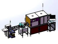
automatic pcb loading and unloading dispensing test automatic line
...ment structure is very complex. it is a very practical equipment for smt industry. the equipment is mature application equipment.
Fish
archibase_planet
free
Fish
...fish
archibase planet
fish aquarium fish toy fish
fish n250113 - 3d model (*.gsm+*.3ds) for interior 3d visualization.
archibase_planet
free
Fish
...fish
archibase planet
fish aquarium fish toy fish
fish n310113 - 3d model (*.gsm+*.3ds) for interior 3d visualization.
archibase_planet
free
Fish
...fish
archibase planet
fish aquarium fish
fish - 3d model (*.gsm+*.3ds) for interior 3d visualization.
archibase_planet
free
Fish
...fish
archibase planet
fish aquarium fish
fish - 3d model (*.gsm+*.3ds) for interior 3d visualization.
turbosquid
$200

Fish Red | Fish 3D | Fish devil | Fish fat
... available on turbo squid, the world's leading provider of digital 3d models for visualization, films, television, and games.
3d_export
free

fish
...fish
3dexport
fish
3ddd
$1
fish
...fish
3ddd
рыба
fish
archibase_planet
free
Fish
...fish
archibase planet
fish sculpture statue
fish - 3d model for interior 3d visualization.
archibase_planet
free

Fish
...fish
archibase planet
fish picturesque element
fish - 3d model (*.gsm+*.3ds) for interior 3d visualization.
archibase_planet
free

Fish
...fish
archibase planet
fish picturesque element
fish - 3d model (*.gsm+*.3ds) for interior 3d visualization.
Simple
turbosquid
$1

Simple goblet (Taca simples)
... available on turbo squid, the world's leading provider of digital 3d models for visualization, films, television, and games.
3d_export
$5
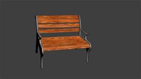
simple bench
...simple bench
3dexport
the simple bench which can be used in simple projects or video-games.
3d_export
$5
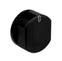
simple knob
...simple knob
3dexport
simple knob
3d_export
$5
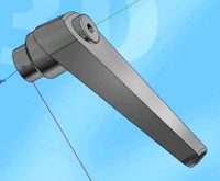
simple handle
...simple handle
3dexport
simple handle
3d_export
$5
simple button
...simple button
3dexport
simple button
3d_export
$5
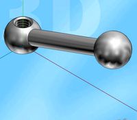
simple spindle
...simple spindle
3dexport
simple spindle
3d_export
$5

simple wheel
...simple wheel
3dexport
simple wheel
3d_export
$5
simple chair
...simple chair
3dexport
simple blue chair
3d_export
free

Simple room
...simple room
3dexport
here is a simple but beautiful room
3ddd
free

SIMPLE | Кресло
...io cianfarra , simple
производитель area declic дизайн giulio cianfarra коллекция simple