Thingiverse
Servo Simulator
by Thingiverse
Last crawled date: 4 years, 2 months ago
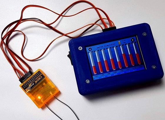
Sometimes it is hard to see what an RC receiver really outputs on each channel because programming of Transmitters and their Mixers sometimes is weird. Even more programming is different between various brands.
This Servo Simulator diplays the output of an RC receiver in microseconds, percentage and as graphical bars/servos.
The valid signal must be between 700-2300us, assuming 1000us=-100%, 1500us=0%, 2000us=+100%.
It uses an Arduino Nano to evaluate up to 8 RC signals and display them on a Nextion LCD. The power supply is a 2S Lipo via Voltage regulator. You can use other supplies but then the battery icon is not valid.
Connect the PWM outputs to 1-8 input channels.
CPPM and SBUS options will be added in future.
Click on the bars to change the colors of them.
Click on the servos to change the angle of a rudder horn.
Click on [nor]/[inv] to change the servo direction.
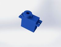
What you need besides the printed case and some screws:
1 Arduino Nano
1 Nextion Display NX4832T035
a voltage regulator for the 5V supply of Nextion LCD, e.g. TRACO POWER TSR-1, plus 2 Elcos 4.7uF and 1 inductor 8.2uH (see schematic)
1 resistor 3k83
1 resistor 26k1
1 3x12 angled pin header (remove 2 positions to separate PWM/CPPM/SBUS)
a prototype PCB to mount the electronic parts
1 Marquardt switch
1 2S Lipo, e.g.800mAh
The wiring is very simple so you can use a prototype PCB. The KiCAD source as well as the Picture ServoSimulator_PCB.png gives some hints on the routing. For details see the schematic.
Upload the .tft file to the Nextion LCD, upload the Arduino sketch to the Nano and have fun!
This Servo Simulator diplays the output of an RC receiver in microseconds, percentage and as graphical bars/servos.
The valid signal must be between 700-2300us, assuming 1000us=-100%, 1500us=0%, 2000us=+100%.
It uses an Arduino Nano to evaluate up to 8 RC signals and display them on a Nextion LCD. The power supply is a 2S Lipo via Voltage regulator. You can use other supplies but then the battery icon is not valid.
Connect the PWM outputs to 1-8 input channels.
CPPM and SBUS options will be added in future.
Click on the bars to change the colors of them.
Click on the servos to change the angle of a rudder horn.
Click on [nor]/[inv] to change the servo direction.
What you need besides the printed case and some screws:
1 Arduino Nano
1 Nextion Display NX4832T035
a voltage regulator for the 5V supply of Nextion LCD, e.g. TRACO POWER TSR-1, plus 2 Elcos 4.7uF and 1 inductor 8.2uH (see schematic)
1 resistor 3k83
1 resistor 26k1
1 3x12 angled pin header (remove 2 positions to separate PWM/CPPM/SBUS)
a prototype PCB to mount the electronic parts
1 Marquardt switch
1 2S Lipo, e.g.800mAh
The wiring is very simple so you can use a prototype PCB. The KiCAD source as well as the Picture ServoSimulator_PCB.png gives some hints on the routing. For details see the schematic.
Upload the .tft file to the Nextion LCD, upload the Arduino sketch to the Nano and have fun!
Similar models
grabcad
free

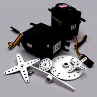
DIY RC servo tester
...diy rc servo tester
grabcad
this is a rc servo tester made with a nextion touch screen and an arduino nano. 3d printed case.
thingiverse
free

Underbed Motion Activated Light by TexWorkshop
...
protoboard
l7805 voltage regulator (to power arduino)
the code and schematics is in "thing" files .
and that's it!
grabcad
free

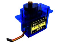
Jetson nano car
...oswclv9vvlrtlbcgw_svddeetcjb7xhwibkxd5ucczxocisiqavd_bwe
servo: https://www.motorobit.com/urun/tower-pro-sg90-rc-mini-servo-motor
grabcad
free

💥Automatic voltage stabilizer on Arduino Nano💥
... on arduino nano💥
grabcad
automatic voltage stabilizer 5 kw. the voltage regulator is controlled by the arduino nano controller.
thingiverse
free
Diode regulator by teacdance
...diode regulator by teacdance
thingiverse
simple diode regulator 2s lipo to 6v rc receiver
thingiverse
free

Foosball table scoreboard by hardas999
... regulator
7) 12x12 tact switch
8) 5v buzzer
9) 850mah 2s lipo battery
10) 470r, 1k, 10k - resistors
11) 500ohm variable resistor
thingiverse
free

Adjustable Benchtop Voltage Supply Case by B00MSTICK
...d a voltage divider, arduino, and lcd to display the voltage.
please feel free to modify or change this to fit your needs.
enjoy!
thingiverse
free

arduino nano case with lcd and encoder by AleyRobotics
... encoder by aleyrobotics
thingiverse
arduino nano case with lcd and encoder
no nano pcb mount. use tape or hot glue to mount it.
cg_trader
$38

XPIDER robot | 3D
..., h bridge l298, voltage regulator x2 7805, lipo battery 2000mah 3s. empresa@penberic.com for the program code and instructions.
thingiverse
free

Nextion 4.3 LCD Enclosure by Wotever
...sure by wotever
thingiverse
here a nextion 4.3 enclosure, i'll leave enough space inside for a pinless arduino nano or a ttl
Servo
turbosquid
$30
Servo
...d model servo for download as obj, blend, dae, stl, and sldpr on turbosquid: 3d models for games, architecture, videos. (1394011)
3d_export
$5

servo motor
...tor
3dexport
it's a simple part of servo motor 0.75kw for used in machines assembly to show specified motor in own project.
turbosquid
$1

Servo Moter
...quid
royalty free 3d model servo moter for download as blend on turbosquid: 3d models for games, architecture, videos. (1650816)
turbosquid
free
Motor/Servo
...osquid
royalty free 3d model motor/servo for download as obj on turbosquid: 3d models for games, architecture, videos. (1522522)
turbosquid
$60

Servo Skull
...
royalty free 3d model servo skull for download as ma and fbx on turbosquid: 3d models for games, architecture, videos. (1318573)
3d_export
$5
Servo 3D Model
...rvo 3d model
3dexport
servo
servo 3d model download .c4d .max .obj .fbx .ma .lwo .3ds .3dm .stl pasqualesiciliano 104590 3dexport
turbosquid
$50
Servo Motor
... available on turbo squid, the world's leading provider of digital 3d models for visualization, films, television, and games.
turbosquid
$49
Servo Motor
...model servo motor for download as 3ds, max, obj, fbx, and stl on turbosquid: 3d models for games, architecture, videos. (1324153)
turbosquid
$29
Servo Set
... available on turbo squid, the world's leading provider of digital 3d models for visualization, films, television, and games.
turbosquid
$10
machine servo
... available on turbo squid, the world's leading provider of digital 3d models for visualization, films, television, and games.
Simulator
archibase_planet
free
Simulator
...simulator
archibase planet
simulator sports equipment sport
simulator full - 3d model for interior 3d visualization.
archibase_planet
free
Simulator
...simulator
archibase planet
sport simulator sports fitness gym
simulator - 3d model for interior 3d visualization.
archibase_planet
free
Simulator
...ulator
archibase planet
simulator sport implements training apparatus
simulator kettler - 3d model for interior 3d visualization.
archibase_planet
free
Simulator
...simulator
archibase planet
weight simulator gym equipment
simulator gym n180111 - 3d model (*.3ds) for interior 3d visualization.
archibase_planet
free
Simulator
...imulator
archibase planet
simulator trainer gym gym equipment
simulator n270711 - 3d model (*.3ds) for interior 3d visualization.
archibase_planet
free
Simulator
...imulator
archibase planet
simulator trainer gym gym equipment
simulator n070511 - 3d model (*.3ds) for interior 3d visualization.
archibase_planet
free
Simulator
...hibase planet
simulator sports equipment gym sport inventory
simulator 12 - 3d model (*.gsm+*.3ds) for exterior 3d visualization.
archibase_planet
free
Simulator
...hibase planet
simulator sports equipment gym sport inventory
simulator 11 - 3d model (*.gsm+*.3ds) for exterior 3d visualization.
archibase_planet
free

Simulator
...chibase planet
simulator sports equipment gym sport inventory
simulator 7 - 3d model (*.gsm+*.3ds) for exterior 3d visualization.
archibase_planet
free
Simulator
...chibase planet
simulator sports equipment gym sport inventory
simulator 1 - 3d model (*.gsm+*.3ds) for exterior 3d visualization.