Thingiverse
Screw threaded telescopic platform (30mm, 5 segments) by Riphaeus
by Thingiverse
Last crawled date: 3 years ago
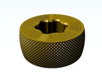
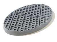
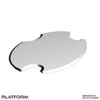
Screw threaded telescopic platform, 30mm deep, 5 segment version.
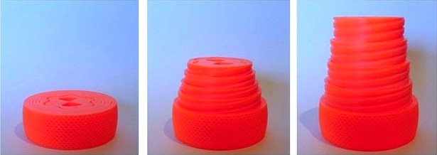
This version is 30mm tall when fully closed and 100mm tall when fully unscrewed.
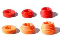
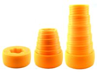
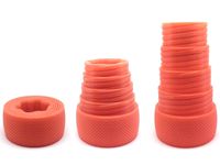
This object is a concentric series of threaded rings, each captive within the next ring out. The rings can be screwed up or down between two end stops positioned such that all of the rings, when screwed down, line up with each other to form a disk, or screwed up so that each extends above the ring directly outside of it to form a taller, cone-like structure.
Because these rings need to be fully captive 3D printing offers the easiest approach to creating this type of structure as all of the rings can be created at the same time in their final position, which avoids having to fit/attach one of the end-stops following creation as separate pieces with subsequent assembly. Note: The 3D models are set-up to print with the upper surface flat on the print bed. This gives a better surface for adhesion but should be remembered if it becomes necessary to apply any force to free up the rings; the rings screw out of the face that was printed downwards.
The point of this is to create an object that can be used support things in the way that, say, a pile of books might be used, but with a fully variable height (within its limits). This would have applications in, for example, DIY or modelling to temporarily support something in the correct position while glue sets.
I should mention that I don't know what the maximum load that these objects could support is (and it is likely to vary with print quality and the specific plastic (or other material) used , however the versions that I have printed in PLA have all been able to support my entire body weight so they are not inherently fragile. Note: plastics used in 3D printing (such as PLA) can fail suddenly by shattering so I would recommend that the consequences of sudden failure is considered in any application, and that if heavy weights are to be supported then the printed object should probably first be tested with a considerably (maybe ten times) heavier weight prior to its use in that application.
A smaller version of this object exists as an option for verifying the capabilities of a printer to create this type of object without wasting too much plastic on failed prints.
Specifically, Ideally each ring should be as close fitting as practical, but obviously if too close then the whole set of rings becomes one solid lump of waste plastic. This is largely down the clearance between rings (horizontal gap between the rings) designed into the 3D models, and the clearance that should be used will depend of the printer being used (how accurately/precisely it can print). To deal with this I have included 5 models for each version, each with a different clearance between the rings. The clearances included are 0.325mm, 0.375mm, 0.425mm, 0.475mm and 0.525mm. The clearance used in each model can be determined from the STL file names. Each STL file ends with "_CL" followed with some numbers and an underscore; replaced the underscore with a decimal point and take the result to be a number in millimetres and that is the clearance used in that file, e.g. "_CL0_475" refers to a 0.475mm clearance. (Note that the size of the 3D model depends on clearance, that is, the models with the larger clearance are wider than those with smaller clearance.)
It would generally be advisable to initially print the 4 segment example of the smaller version of this object to find out which value of clearance works with your printer prior to trying to crate a larger version as that will minimise the waste plastic that will result from failed prints.
The thread faces overhang and it is generally better to print overhangs with low layer heights. I have been printing these with a 0.1mm layer height.
Other details from the file names are, "S" is followed by the number of segments, and "H" is followed by the number of millimetres that represent the height of the base units.
I have included optional end cap models for these 30mm versions. They are designed to press-fit together and into the ring structures and give a flatter upper surface to the central ring.
Related Items
Screw threaded telescopic platform (20mm, 4 and 5 segment versions)Screw threaded telescopic platform (30mm, 6 segment version)Screw threaded telescopic platform (40mm, 5 segment version)Screw threaded telescopic platform (40mm, 6 segment version)Screw threaded telescopic platform (40mm, 7 segment version)
Update (22nd September 2019)
I received a comment form th008 suggesting that these would be easier to print if the clearance between the rings was larger where the from contacts the build plate. This would avoid any 'elephants foot' effect from gluing the adjacent rings together and make them easier to print. It tool some thought to work out how to do that without having to re-do the design from the start, but I figured that out and have now made that change. Specifically, where the form contacts the print bed the clearances between the rings is not 0.4mm wider, with that extra clearance tapering back to the normal profile within the first 2.5 mm in height. This change did indeed make these much easier to print reliably.
This version is 30mm tall when fully closed and 100mm tall when fully unscrewed.
This object is a concentric series of threaded rings, each captive within the next ring out. The rings can be screwed up or down between two end stops positioned such that all of the rings, when screwed down, line up with each other to form a disk, or screwed up so that each extends above the ring directly outside of it to form a taller, cone-like structure.
Because these rings need to be fully captive 3D printing offers the easiest approach to creating this type of structure as all of the rings can be created at the same time in their final position, which avoids having to fit/attach one of the end-stops following creation as separate pieces with subsequent assembly. Note: The 3D models are set-up to print with the upper surface flat on the print bed. This gives a better surface for adhesion but should be remembered if it becomes necessary to apply any force to free up the rings; the rings screw out of the face that was printed downwards.
The point of this is to create an object that can be used support things in the way that, say, a pile of books might be used, but with a fully variable height (within its limits). This would have applications in, for example, DIY or modelling to temporarily support something in the correct position while glue sets.
I should mention that I don't know what the maximum load that these objects could support is (and it is likely to vary with print quality and the specific plastic (or other material) used , however the versions that I have printed in PLA have all been able to support my entire body weight so they are not inherently fragile. Note: plastics used in 3D printing (such as PLA) can fail suddenly by shattering so I would recommend that the consequences of sudden failure is considered in any application, and that if heavy weights are to be supported then the printed object should probably first be tested with a considerably (maybe ten times) heavier weight prior to its use in that application.
A smaller version of this object exists as an option for verifying the capabilities of a printer to create this type of object without wasting too much plastic on failed prints.
Specifically, Ideally each ring should be as close fitting as practical, but obviously if too close then the whole set of rings becomes one solid lump of waste plastic. This is largely down the clearance between rings (horizontal gap between the rings) designed into the 3D models, and the clearance that should be used will depend of the printer being used (how accurately/precisely it can print). To deal with this I have included 5 models for each version, each with a different clearance between the rings. The clearances included are 0.325mm, 0.375mm, 0.425mm, 0.475mm and 0.525mm. The clearance used in each model can be determined from the STL file names. Each STL file ends with "_CL" followed with some numbers and an underscore; replaced the underscore with a decimal point and take the result to be a number in millimetres and that is the clearance used in that file, e.g. "_CL0_475" refers to a 0.475mm clearance. (Note that the size of the 3D model depends on clearance, that is, the models with the larger clearance are wider than those with smaller clearance.)
It would generally be advisable to initially print the 4 segment example of the smaller version of this object to find out which value of clearance works with your printer prior to trying to crate a larger version as that will minimise the waste plastic that will result from failed prints.
The thread faces overhang and it is generally better to print overhangs with low layer heights. I have been printing these with a 0.1mm layer height.
Other details from the file names are, "S" is followed by the number of segments, and "H" is followed by the number of millimetres that represent the height of the base units.
I have included optional end cap models for these 30mm versions. They are designed to press-fit together and into the ring structures and give a flatter upper surface to the central ring.
Related Items
Screw threaded telescopic platform (20mm, 4 and 5 segment versions)Screw threaded telescopic platform (30mm, 6 segment version)Screw threaded telescopic platform (40mm, 5 segment version)Screw threaded telescopic platform (40mm, 6 segment version)Screw threaded telescopic platform (40mm, 7 segment version)
Update (22nd September 2019)
I received a comment form th008 suggesting that these would be easier to print if the clearance between the rings was larger where the from contacts the build plate. This would avoid any 'elephants foot' effect from gluing the adjacent rings together and make them easier to print. It tool some thought to work out how to do that without having to re-do the design from the start, but I figured that out and have now made that change. Specifically, where the form contacts the print bed the clearances between the rings is not 0.4mm wider, with that extra clearance tapering back to the normal profile within the first 2.5 mm in height. This change did indeed make these much easier to print reliably.
Similar models
thingiverse
free

Screw threaded telescopic platform (30mm, 6 segments) by Riphaeus
...ng back to the normal profile within the first 2.5 mm in height. this change did indeed make these much easier to print reliably.
thingiverse
free
Screw threaded telescopic platform (20mm) by Riphaeus
...ng back to the normal profile within the first 2.5 mm in height. this change did indeed make these much easier to print reliably.
thingiverse
free
Screw threaded telescopic platform (40mm, 6 segments) by Riphaeus
...ng back to the normal profile within the first 2.5 mm in height. this change did indeed make these much easier to print reliably.
thingiverse
free
Screw threaded telescopic platform (40mm, 5 segments) by Riphaeus
...ng back to the normal profile within the first 2.5 mm in height. this change did indeed make these much easier to print reliably.
thingiverse
free
Screw threaded telescopic platform (40mm,7 Segments) by Riphaeus
...ng back to the normal profile within the first 2.5 mm in height. this change did indeed make these much easier to print reliably.
thingiverse
free

Thick Wall plug by yYzGq7PIx2wIyLk
...m in diameter
i used it once and it worked fine.
i had to print at 60% flow rate to have the segments not attached to each other.
thingiverse
free

30MM to 1" Scope Ring Adapter by f1uke
...infill.
if you connect two together, it will form a ring, and if you lay this ring on the table, it will have the height of 2cm.
thingiverse
free
Customizable Jack Screw to adjust height of Corners on MPCNC by GeoDave
...mmht_rev30.stl
print time 100mm tot_ht: 5:01:42 at 60%infill 1.5oz
total of 14.2oz of plastic & print time of about 44 hours.
thingiverse
free
GoPro Tripod Adapter with 1/4"-20 thread for standard mount by LSM87
...this adapter. or use a longer screw (thread should be at least 25mm or 30mm, i haven't tested yet.)
printed with 0.2mm layer.
thingiverse
free
Parametric Motor Retainer by gravatite
...rinted plastics! be sure you have a strong bond between the retainer ring and the motor mount tube before you use it for flight.
Riphaeus
thingiverse
free

Soap Dish by Riphaeus
...be smooth printing with a small layer height is appropriate (~ 0.1mm), along with a reasonably high infill percentage (30-50%).
thingiverse
free

Bottle coupling/draining device by Riphaeus
....
the threads work best if printed at relatively low layer heights, i used 0.1mm. no support material is necessary to print this.
thingiverse
free

Octagonal Miniature Figure Bases (20 to 50mm widths) by Riphaeus
...ith a small layer height ( <= 0.1mm).
update
i added versions of the random texture-topped base that omit the outer upper rim.
thingiverse
free
Square Grill Panel Miniature Figure Bases Set by Riphaeus
...rial square grill (1 inch grid)
openlock intermediate step riser floor tiles set - sci-fi / industrial square grill (1 inch grid)
thingiverse
free

Nutcracker by josedpedroso
...nutcracker by josedpedroso thingiverse riphaeus#39; nutcracker has a plunger with internal structure for reinforcement,...
thingiverse
free
Screw threaded telescopic platform (20mm) by Riphaeus
...ng back to the normal profile within the first 2.5 mm in height. this change did indeed make these much easier to print reliably.
thingiverse
free
Screw threaded telescopic platform (40mm, 6 segments) by Riphaeus
...ng back to the normal profile within the first 2.5 mm in height. this change did indeed make these much easier to print reliably.
thingiverse
free
Screw threaded telescopic platform (30mm, 6 segments) by Riphaeus
...ng back to the normal profile within the first 2.5 mm in height. this change did indeed make these much easier to print reliably.
thingiverse
free
Screw threaded telescopic platform (40mm, 5 segments) by Riphaeus
...ng back to the normal profile within the first 2.5 mm in height. this change did indeed make these much easier to print reliably.
Telescopic
archibase_planet
free
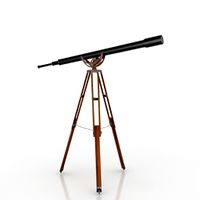
Telescope
...telescope
archibase planet
telescope spyglass
telescope n220408 - 3d model (*.gsm+*.3ds) for interior 3d visualization.
3d_export
free

telescope
...telescope
3dexport
telescope 3d model, more files here:
3d_export
free

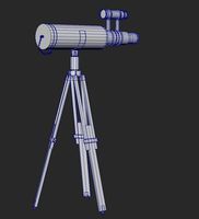
telescope
...telescope
3dexport
telescope refractor on a tripod. can be used as part of the interior.
3d_ocean
$8

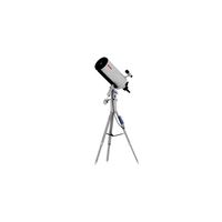
Telescope
...antique binocular glass magnify monocular naval optic optical pirate spy spyglass telescope viewer vision
nice model of telescope
turbosquid
free
telescope
...scope
turbosquid
free 3d model telescope for download as obj on turbosquid: 3d models for games, architecture, videos. (1638257)
turbosquid
$35

Telescope
...rbosquid
royalty free 3d model telescope for download as fbx on turbosquid: 3d models for games, architecture, videos. (1515061)
turbosquid
$6

Telescope
...rbosquid
royalty free 3d model telescope for download as max on turbosquid: 3d models for games, architecture, videos. (1665123)
turbosquid
$5

Telescope
...osquid
royalty free 3d model telescope for download as blend on turbosquid: 3d models for games, architecture, videos. (1603403)
turbosquid
$99

Telescope
...y free 3d model telescope for download as blend, fbx, and obj on turbosquid: 3d models for games, architecture, videos. (1609065)
turbosquid
$30
telescope
...lty free 3d model telescope for download as max, obj, and fbx on turbosquid: 3d models for games, architecture, videos. (1325340)
Segments
archibase_planet
free

Segment
...segment
archibase planet
playground sports ground
segment 1 - 3d model (*.gsm+*.3ds) for interior 3d visualization.
archibase_planet
free

Segment
...segment
archibase planet
playground chute slide
segment 2 - 3d model (*.gsm+*.3ds) for interior 3d visualization.
archibase_planet
free

Segment
...segment
archibase planet
playground sports ground
segment 3 - 3d model (*.gsm+*.3ds) for interior 3d visualization.
archibase_planet
free
Segment
...segment
archibase planet
sports ground playground
segment 4 - 3d model (*.gsm+*.3ds) for interior 3d visualization.
archibase_planet
free

Segment
...segment
archibase planet
playground sports ground
segment 5 - 3d model (*.gsm+*.3ds) for interior 3d visualization.
archibase_planet
free
Segment
...segment
archibase planet
chute playground slide
segment 6 - 3d model (*.gsm+*.3ds) for interior 3d visualization.
archibase_planet
free

Segment
...segment
archibase planet
sports ground playground
segment 8 - 3d model (*.gsm+*.3ds) for interior 3d visualization.
archibase_planet
free

Segment
...segment
archibase planet
playground sports ground
segment 7 - 3d model (*.gsm+*.3ds) for interior 3d visualization.
archibase_planet
free

Segment
...segment
archibase planet
playground sports ground
segment 9 - 3d model (*.gsm+*.3ds) for interior 3d visualization.
archibase_planet
free

Segment
...segment
archibase planet
playground sports ground
segment 10 - 3d model (*.gsm+*.3ds) for interior 3d visualization.
30Mm
turbosquid
$38
30mm
... available on turbo squid, the world's leading provider of digital 3d models for visualization, films, television, and games.
turbosquid
$1
Base insert - Stone&Rails 30mm
...odel base insert - stone&rails 30mm for download as blend on turbosquid: 3d models for games, architecture, videos. (1325627)
3d_export
$5

Front 30mm Lift Kit for 1996-2004 Nissan Pathfinder and 1997-2003 Infiniti QX4
...port
front 30mm lift kit for 1996-2004 nissan pathfinder r50, terrano r50, regulus 1997-2003 infiniti qx4 - front strut spacers
3d_export
$8
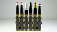
soviet russian 30mm aircraft shells 30x165
...tnyy)<br>- 30x165 fz - high explosive incendiary (tr. fugasno-zazhigatel'nyy)<br>*modifier - subdivision surface
3ddd
$1

Бамбук
...бамбук 3ddd бамбук производитель: - модель: - размеры: d-30mm ...
3d_export
$5

soap
...3dexport 3d model of a soap bar. .stl file 30mm x 60mm...
3d_export
$5
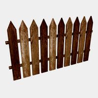
fense
...of the back boards is 50mm, width 2050mm, length 30mm<br>texture link -...
3ddd
$1

Молоток
...инструмент производитель: douglas _http://www.douglastool.com/ _ модель: hammer размеры: w-150mm, d-30mm ...
3d_export
$8
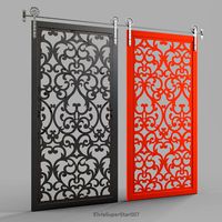
sliding door vintage
...sliding door vintage 3dexport 2100mm x 1000mm x 30mmlt;br>3dsmax 2011 +...
3ddd
$1
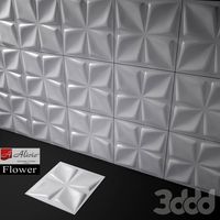
3D панели Alivio Flower
...3ddd панель w 600mm / h 600mm / d 30mm стек не свернут...
Platform
archibase_planet
free
Platform
...rm
archibase planet
platform
platform stefano galli savio cerrato n040413 - 3d model (*.gsm+*.3ds) for exterior 3d visualization.
turbosquid
$4

Platform
...d
royalty free 3d model platform for download as max and fbx on turbosquid: 3d models for games, architecture, videos. (1363559)
3d_export
$5
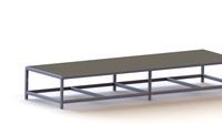
WORKING PLATFORM
...working platform
3dexport
working platform 4000x3000x1500mm
turbosquid
$20
Platform
... available on turbo squid, the world's leading provider of digital 3d models for visualization, films, television, and games.
turbosquid
$9
Platform
... available on turbo squid, the world's leading provider of digital 3d models for visualization, films, television, and games.
turbosquid
$1
Platform
... available on turbo squid, the world's leading provider of digital 3d models for visualization, films, television, and games.
turbosquid
$1

Platform
... available on turbo squid, the world's leading provider of digital 3d models for visualization, films, television, and games.
turbosquid
$1
Platform
... available on turbo squid, the world's leading provider of digital 3d models for visualization, films, television, and games.
3d_ocean
$19

Drilling Platform
...rm for coastal areas. designed to perform drilling operations. include standart materials scene and v-ray scene with environment.
3d_export
$15
steel grill platform
...steel grill platform
3dexport
steel grill platform
Threaded
3d_export
$5

threaded handle
...threaded handle
3dexport
threaded handle
turbosquid
free

threaded
... available on turbo squid, the world's leading provider of digital 3d models for visualization, films, television, and games.
3d_ocean
$5
Tangle of thread
... tangle thread triangles – 36 in one strand in scene 300 thread includes materials includes 3 colors tangle thread in psd for ...
3d_export
$5
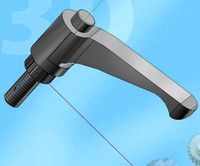
threaded lock handle
...threaded lock handle
3dexport
threaded lock handle
3d_export
$5
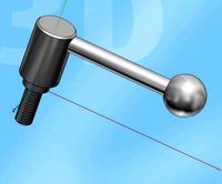
threaded machine handle
...threaded machine handle
3dexport
threaded machine handle
3d_export
$5

threaded door knob
...threaded door knob
3dexport
threaded door knob
3d_export
$5
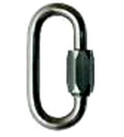
threaded rope ring
...threaded rope ring
3dexport
threaded rope ring
3d_export
$5

threaded door knob
...threaded door knob
3dexport
threaded door knob
turbosquid
$56

Threaded Inserts
... available on turbo squid, the world's leading provider of digital 3d models for visualization, films, television, and games.
turbosquid
$10
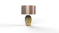
Thread Lamp
... available on turbo squid, the world's leading provider of digital 3d models for visualization, films, television, and games.
Screw
3d_export
$5
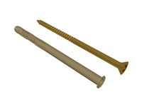
screw
...screw
3dexport
screw
turbosquid
$29

Screw driver and screws
... available on turbo squid, the world's leading provider of digital 3d models for visualization, films, television, and games.
3d_ocean
$2
Screw
... steel twist wood screw
screw 3d model in 2 different materials real world scale rendered with mental ray file formats: .max .obj
3d_ocean
$4

Screw
...n
3d bolt male mechanic metal nut parts prop propeller schraube schraubenmutter screw steel twist
screw 3d model, clean modeling.
turbosquid
$2
screw
...crew
turbosquid
royalty free 3d model screw for download as on turbosquid: 3d models for games, architecture, videos. (1198271)
turbosquid
free
Screw
...screw
turbosquid
free 3d model screw for download as obj on turbosquid: 3d models for games, architecture, videos. (1240851)
3d_ocean
$2
Frame Screw
...frame screw
3docean
construction screw
a frame screw and plug.
turbosquid
$27

screw
...w
turbosquid
royalty free 3d model screw for download as max on turbosquid: 3d models for games, architecture, videos. (1334064)
turbosquid
$20

SCREW
...
turbosquid
royalty free 3d model screw for download as sldas on turbosquid: 3d models for games, architecture, videos. (729733)
turbosquid
$1
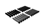
Screws
...
turbosquid
royalty free 3d model screws for download as max on turbosquid: 3d models for games, architecture, videos. (1640360)
5
3d_export
$5
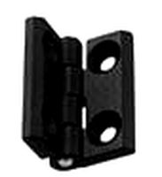
hinge 5
...hinge 5
3dexport
hinge 5
turbosquid
$10
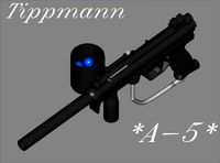
A-5
... available on turbo squid, the world's leading provider of digital 3d models for visualization, films, television, and games.
turbosquid
$2
A-5
... available on turbo squid, the world's leading provider of digital 3d models for visualization, films, television, and games.
turbosquid
$12

Calligraphic Digit 5 Number 5
...hic digit 5 number 5 for download as max, obj, fbx, and blend on turbosquid: 3d models for games, architecture, videos. (1389333)
3ddd
$1

5 роз
...5 роз
3ddd
5 роз в стеклянной вазе
design_connected
$11

iPhone 5
...iphone 5
designconnected
apple iphone 5 computer generated 3d model.
3ddd
$1
Lola 5
...lola 5
3ddd
miniforms
lola 5 miniforms 300*65*134
3ddd
$1

Nexus 5
...dd
nexus , phone , телефон
google nexus 5 phone
3d_ocean
$15

iPhone 5
...iphone 5
3docean
3d 4d apple cinema iphone model modeling phone screen texture
iphone 5 3d model and texture realistic iphone 5.
3d_ocean
$9

chanel 5
...chanel 5
3docean
books chanel
quality models perfum chanel 5 and books.