Thingiverse
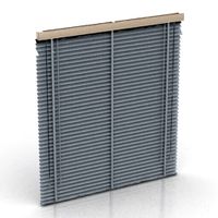
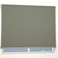
Roller Blinds NEMA17 by igorsouz002
by Thingiverse
Last crawled date: 3 years, 1 month ago
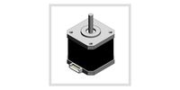
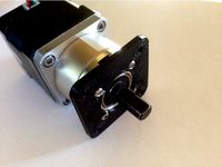
I made an automatic roller blind from a spare NEMA17 stepper that was laying around, I didn't want to buy a new one with planetary reduction neither another DC motor, so here it is.
My original blinds used a tube with 29mm external and 28mm internal diameter.
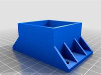
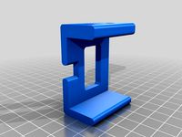
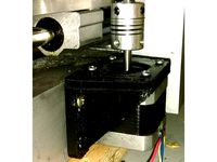
It's needed just 2 screws to secure the tube holders to the wall supports (almost as a shaft but it will just hold everything in place, they must spin freely) and a grub allen M3 to hold the motor's pinion in place.
The electronics I used were a NEMA17 stepper, a NodeMCU, a stepper driver (initially an A4988, then a TMC2208), a step down and a 12V power supply. I put everything together in a simple prototyping PCB for now.
I'm using the Tasmota firmware, very well documented here: https://tasmota.github.io/docs/Blinds-and-Shutters/
This could vary a lot, depends how you want to control the motor.
The 1st version was just a reduction gear, going straight to the blind's tube, very fast but didn't have a brake, so the blinds felt as soon the stepper was powered off.
The 2nd, I adapted the original blinds cord's system that has a spring that acts as a brake, cool design but with a play that could not be compensated without a closed loop system.
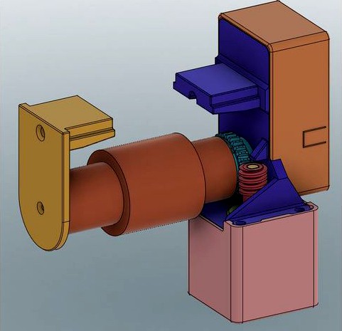
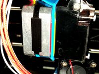
This version n. 3 is slower but uses a worm gear that naturally locks the movement, very precise and has no play.
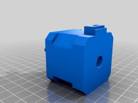
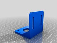
It is VERY important to play attention to tolerances in the motor shaft's hole, remember the pinion will withstand the weight of the whole blind, it needs to be tight and secure. The Support - Motor Side.stl has a dent that will hold the pinion from pop out but it still could spin freely if the shaft's screw doesn't have a flat side to sit.
I attached the .step and fusion files to make it easier to adapt.
The critical part to print is the worm gear, I used PETG and 0.12mm/layer, with the hole facing up and the "spiral", down. I don't see any problem to use PLA at 0.28mm/layer for everything else, maybe the Tube Holder - Motor Side.stl would be better at 0.12-0.20mm/layer due to the gear, but it will work anyway.
Print details:
No support needed
Worm gear: Use 999 walls
Supports: use at least 50% of infill and 4 walls
20% infill for the rest are plenty.
My original blinds used a tube with 29mm external and 28mm internal diameter.
It's needed just 2 screws to secure the tube holders to the wall supports (almost as a shaft but it will just hold everything in place, they must spin freely) and a grub allen M3 to hold the motor's pinion in place.
The electronics I used were a NEMA17 stepper, a NodeMCU, a stepper driver (initially an A4988, then a TMC2208), a step down and a 12V power supply. I put everything together in a simple prototyping PCB for now.
I'm using the Tasmota firmware, very well documented here: https://tasmota.github.io/docs/Blinds-and-Shutters/
This could vary a lot, depends how you want to control the motor.
The 1st version was just a reduction gear, going straight to the blind's tube, very fast but didn't have a brake, so the blinds felt as soon the stepper was powered off.
The 2nd, I adapted the original blinds cord's system that has a spring that acts as a brake, cool design but with a play that could not be compensated without a closed loop system.
This version n. 3 is slower but uses a worm gear that naturally locks the movement, very precise and has no play.
It is VERY important to play attention to tolerances in the motor shaft's hole, remember the pinion will withstand the weight of the whole blind, it needs to be tight and secure. The Support - Motor Side.stl has a dent that will hold the pinion from pop out but it still could spin freely if the shaft's screw doesn't have a flat side to sit.
I attached the .step and fusion files to make it easier to adapt.
The critical part to print is the worm gear, I used PETG and 0.12mm/layer, with the hole facing up and the "spiral", down. I don't see any problem to use PLA at 0.28mm/layer for everything else, maybe the Tube Holder - Motor Side.stl would be better at 0.12-0.20mm/layer due to the gear, but it will work anyway.
Print details:
No support needed
Worm gear: Use 999 walls
Supports: use at least 50% of infill and 4 walls
20% infill for the rest are plenty.
Similar models
thingiverse
free

Nema 17 / 23 Stepper Manual Knob by buffcleb
...bolt that holds the mount to the shaft.
just a note... the photo is with nema23 motors... on nema17s these would be very large...
thingiverse
free

DC 12V 35RPM Turbo Worm Geared Motor High Torque Turbine Worm Gear Box Reduction Motor 6mm Shaft JSX255-370 by willy1067
...ly1067
thingiverse
dc 12v 10rpm-100rpm turbo worm geared motor high torque turbine worm gear box reduction motor 6mm shaft model
thingiverse
free
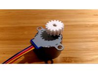
Gear for 28BYJ-48 stepper motor by makerbard
...ck and pinion gear set example" by dreyfusduke. i altered the gear so that it fits on the shaft of a 28byj-48 stepper motor.
thingiverse
free
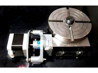
Sherline Rotary Table CNC Conversion by kohjbeng
... x m3x10 screws - to secure the mount and shaft couplers to the stepper shaft and worm gear shaft
5) 7 (or possibly less) m3 nuts
3dwarehouse
free

Stepper Motor with worm gear
...stepper motor with worm gear
3dwarehouse
stepper motor with worm gear
thingiverse
free

Extruder NEMA17 Geared Stepper Motor by hghu
...extruder nema17 geared stepper motor by hghu
thingiverse
extruder nema17 geared stepper motor
grabcad
free

Worm Gear Reducer
... because the worm gear reducer is one of the sleekest reduction gearboxes available due to the small diameter of its output gear.
thingiverse
free

3:1 Planetary Geared Extruder
...f bearings
added pinion gear for smaller motor without recess or full length d drive to cater for extended d drine on the pinion.
grabcad
free

Worm Gear And Rack Pinion Mechanism
...ad
the worm gear is introduced with rack and pinion with the connecting shaft.
designed in solidworks, and with motion analysis.
grabcad
free

Harmonic drive reducer with stepper motor or BLDC motor
...3 stepper motor with harmonic drive reducer for compact application where a hollow shaft stepper motor's torque can not meet.
Nema17
turbosquid
$1
Nema17 holder
...quid
royalty free 3d model nema17 holder for download as ipt on turbosquid: 3d models for games, architecture, videos. (1165167)
3d_export
$5
Stepper motor Nema17 17HS4401
...stepper motor nema17 17hs4401
3dexport
thingiverse
free
nema17
...nema17
thingiverse
moteur nema 17
thingiverse
free

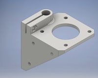
Bracket for Nema17
...bracket for nema17
thingiverse
bracket for nema17 ( axis y, z)
thingiverse
free
nema17 mount by JonBAL
...nema17 mount by jonbal
thingiverse
nema17 mount
thingiverse
free
Support Nema17 by perryluca
...support nema17 by perryluca
thingiverse
motor support for nema17
thingiverse
free
Nema17 Mount by sitt
...nema17 mount by sitt
thingiverse
nema17 mount, abs, 30%infill
thingiverse
free
NEMA17 pg5 to Nema17 Adapter by kraegar
... (planetary geared nema 17) on a normal nema 17 motor project mounting plate.
i printed in atomic carbon fiber petg for strength.
thingiverse
free
Mount for NEMA17 by ImHuman
...mount for nema17 by imhuman
thingiverse
copy parts. mount for stepper motor nema17.
thingiverse
free
Seal nema17 by lisent
...seal nema17 by lisent
thingiverse
this is a seal for create separation between the nema17 and the support mount.
Blinds
archibase_planet
free

Blind
...blind
archibase planet
blind venetian blind jalousie
blind - 3d model for interior 3d visualization.
archibase_planet
free
Blinds
...blinds
archibase planet
blinds blind jalousie
blinds n270313 - 3d model (*.gsm+*.3ds) for interior 3d visualization.
archibase_planet
free
Blind
...blind
archibase planet
blind venetian blind jalousie
blind n031007 - 3d model (*.gsm+*.3ds) for interior 3d visualization.
archibase_planet
free
Blind
...blind
archibase planet
blind jalousie
blind - 3d model for interior 3d visualization.
archibase_planet
free

Blind
...blind
archibase planet
blind sunblind jalousie
blind - 3d model for interior 3d visualization.
archibase_planet
free

Blind
...blind
archibase planet
blind curtain
blind - 3d model (*.gsm+*.3ds) for interior 3d visualization.
archibase_planet
free
Blind
...blind
archibase planet
blind jalousie
venetian blind 1- 3d model for interior 3d visualization.
archibase_planet
free

Blind
...blind
archibase planet
venetian blind jalousie
venetian blind 2 - 3d model for interior 3d visualization.
3d_ocean
$9
Blinds
...blinds
3docean
blinds curtain decor decoration drapes flat furniture home house interior jalousie
?urtains and blinds
archibase_planet
free

Blind
...blind archibase planet venetian blind jalousie so blinds - 3d model (*.gsm+*.3ds) for interior 3d...
Roller
turbosquid
$26
Roller A
...urbosquid
royalty free 3d model roller a for download as fbx on turbosquid: 3d models for games, architecture, videos. (1350603)
turbosquid
$3
Roller
...oyalty free 3d model roller for download as 3ds, max, and obj on turbosquid: 3d models for games, architecture, videos. (1460818)
3ddd
$1
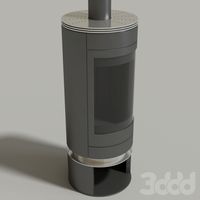
edilkamin roller
...edilkamin roller
3ddd
камин
edilkamin roller 360
3ddd
$1
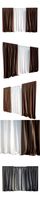
Roller Blinds
...roller blinds
3ddd
рулонная
roller blinds black out finish
turbosquid
$50

Roller
... roller for download as max, max, c4d, max, max, fbx, and obj on turbosquid: 3d models for games, architecture, videos. (1700762)
3d_export
$10
rollers
...lers
3dexport
this is low-poly model of rollers.<br>model:<br>- low-poly<br>- textured<br>- uv unwrapped
3d_export
$28
Roller 3D Model
...roller 3d model
3dexport
roller construction boss evil
roller 3d model adagio15740837 50561 3dexport
3d_export
$6
hopper roller conveyor
...hopper roller conveyor
3dexport
hopper roller conveyor
3d_export
$12

roller skates
...roller skates
3dexport
3d_ocean
$19
roller skate
...can scanned skates skating sport
3d scan of roller skate. the model has been retopologized and made fully compatible with zbrush.