Thingiverse
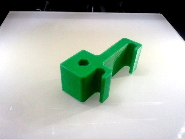
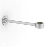
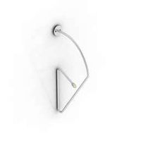
Rod to Rod dial indicator bracket by Dracos
by Thingiverse
Last crawled date: 3 years ago
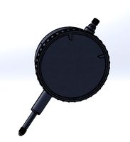
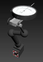
I made this dial indicator bracket to allow for aligning X carriage rods to the Y rods. Most similar bracket designs place the dial mount between the rod clips, which only allows the tool tip to reach the bed. However, X axis rods should be Y axis rods to ensure the carriage travel is aligned to the Y rods. The bed has its own positioning mechanism (leveling screws) which should be removed from the rod (axis) squaring process.
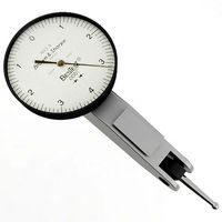
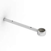
To get the probe to sit correctly on the Y rods, remove the ball end.
Required hardware (per bracket):
(1) m5x20 hex cap bolt
(1) m5 locknut
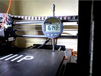
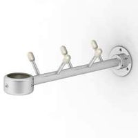
For best results, adjust your bed to it's lowest position and home your printer on Z to allow the probes to reach the Y rods. If you can't move your print bed out of the way, mount the brackets facing backwards. Turn on the indicator before mounting and be careful not to zero it out. Make sure the bracket is seated all the way down on the rods and that the (sans-ball) probe is on top of the Y rod.
Why do I have two indicators? Because the X rods pivot at points outside the carriage travel range; adjusting one Z rod will change the height all the way across to the opposite mount point of the X rods. Having two indicators in place allows both sides to be adjusted simultaneously for faster, more accurate results.
To get the probe to sit correctly on the Y rods, remove the ball end.
Required hardware (per bracket):
(1) m5x20 hex cap bolt
(1) m5 locknut
For best results, adjust your bed to it's lowest position and home your printer on Z to allow the probes to reach the Y rods. If you can't move your print bed out of the way, mount the brackets facing backwards. Turn on the indicator before mounting and be careful not to zero it out. Make sure the bracket is seated all the way down on the rods and that the (sans-ball) probe is on top of the Y rod.
Why do I have two indicators? Because the X rods pivot at points outside the carriage travel range; adjusting one Z rod will change the height all the way across to the opposite mount point of the X rods. Having two indicators in place allows both sides to be adjusted simultaneously for faster, more accurate results.
Similar models
thingiverse
free
Bed Leveling Bracket by kbrint
...%2f0.00005%27%27+digital+probe+indicator+dial+test+gauge+range+0-25.4mm%2f1%27%27+dial+test+indicators+electronic+indicator+gauge
thingiverse
free

MPSMv2 Dial Indicator Mount by Kadah
...price mp select mini z axis adjustable endstopmy modified endstop mount for v2
made in fusion 360. step file included. enjoy. :)
thingiverse
free

Dial Indicator Mount - Creality Ender 3
...d:
large probe shaft - 8mm od
small probe shaft - 4.5mm od
thank you for looking, and please let me know your makes and comments!
thingiverse
free

FLSun i3 Factory Printable Parts Collection (linear rod and bearing version) by macelius
...xis belt tensioner (2 parts)
y-axis bed rail mounts
z-axis top corner brackets - 10mm tall
z-axis top corner brackets - 40mm tall
thingiverse
free

easy tool for nyloc nut mod for prusa for mk2,5s mk3s, mk3s+ by rosch8
... the bed to one distance . that way your bed will be perfectly flat. i was able to set it in range 0,02 mm. i think it is enough.
thingiverse
free

Wanhao Dial Indicator Storage Bracket by tonycwang
...l remove the bottom two bolts on the left z-axis upright. then use two m3x8mm bolts to install the storage bracket to the frame.
thingiverse
free

Fan Mount for Dial Indicator by TechnoSwiss
...e from measuring all the way to the back of the bed. you're results may vary. dial indication is simply press-fit into mount.
thingiverse
free

AM8 Limit switch mounting brackets by edsimmons
...xis movement.
you can download the stl files and print with your choice of tools, or grab both openscad files and edit as needed.
thingiverse
free

Magnetic dial indicator mount for i3 Plus by WaveSupportApparatus
...ct polarity.
remove the mount + magnet from the printer together. hammer the magnet into the hole.
repeat for the second magnet.
thingiverse
free

Quick Release Dial test indicator by PrototypeMe
...dd this dial test indicator holder and level the bed without any tools getting in the way.
the z-axis may need adjusting first.
Dracos
turbosquid
$150

Draco
... available on turbo squid, the world's leading provider of digital 3d models for visualization, films, television, and games.
3ddd
$1

Draco
...draco
3ddd
дракон , дракон profi
игрушка, мягкая, дракон
3d_export
$10

Toy Draco 3D Model
...toy draco 3d model
3dexport
toy draco
toy draco 3d model nlena1208 64516 3dexport
turbosquid
$5

Little Draco
...odel little draco for download as c4d, obj, dae, fbx, and stl on turbosquid: 3d models for games, architecture, videos. (1708340)
3d_export
$10

dracaena draco dragon tree
...dracaena draco dragon tree
3dexport
dracaena draco | dragon tree
turbosquid
$39

Chinese Draco Pendant
...model chinese draco pendant for download as max, obj, and fbx on turbosquid: 3d models for games, architecture, videos. (1226306)
turbosquid
$20

BC Rich Draco Guitar
... available on turbo squid, the world's leading provider of digital 3d models for visualization, films, television, and games.
turbosquid
$69

Electric guitar B C Rich DRACO
... available on turbo squid, the world's leading provider of digital 3d models for visualization, films, television, and games.
3d_export
$5

Dracaena Draco trees
...00 cm<br>formats<br>3ds max - vray / corona<br>cinema4d<br>blender<br>obj<br>fbx<br>stl
3d_export
$5
Red Dragon 3D Model
...red dragon 3d model
3dexport
red dragon monster skyrim draco dragons
red dragon 3d model liquidsunproductions 63440 3dexport
Dial
3ddd
$1

Hidra Dial
...a dial , биде , унитаз
hidra dial унитаз + биде
turbosquid
$30
Dial Indicator
...ree 3d model dial indicator for download as 3ds, max, and obj on turbosquid: 3d models for games, architecture, videos. (1302779)
3d_export
$7
dial indicator
...r is any of various instruments used to accurately measure small distances and angles, and amplify them to make them more obvious
turbosquid
$99

Phone Dialing
... available on turbo squid, the world's leading provider of digital 3d models for visualization, films, television, and games.
turbosquid
$25
Dial Indicator
... available on turbo squid, the world's leading provider of digital 3d models for visualization, films, television, and games.
turbosquid
$15

Dial Indicator
... available on turbo squid, the world's leading provider of digital 3d models for visualization, films, television, and games.
3d_ocean
$12

Old Rotary Dial Telephone
...ial phone telephone
this is a model of a rotary dial telephone made in cinema4d file contains the following files: .obj .c4d .3ds
3ddd
$1

Dialing kitchen
...зон , базилик , лук
polys: 48 893
verts: 54 349
3d_export
$45
Dial Indicator 3D Model
...tion metalworking hurco indicating geometric dimensioning tolerancing bridgeport
dial indicator 3d model plutonius 63521 3dexport
turbosquid
$38

Sun Dial 3ds
... available on turbo squid, the world's leading provider of digital 3d models for visualization, films, television, and games.
Indicator
3ddd
$1

Indice Sofa
...indice sofa
3ddd
indice sofa , roche bobois
indice sofa roche bobois
archive3d
free
Indicator 3D Model
...sor indicator pointer
indicator n130508 - 3d model (*.gsm+*.3ds) for interior 3d visualization.
turbosquid
$26

Km indicator
...squid
royalty free 3d model km indicator for download as max on turbosquid: 3d models for games, architecture, videos. (1153786)
turbosquid
free

Road Indicator
...d
royalty free 3d model road indicator for download as blend on turbosquid: 3d models for games, architecture, videos. (1299938)
turbosquid
$30
Dial Indicator
...ree 3d model dial indicator for download as 3ds, max, and obj on turbosquid: 3d models for games, architecture, videos. (1302779)
3d_export
$7
dial indicator
...r is any of various instruments used to accurately measure small distances and angles, and amplify them to make them more obvious
turbosquid
$3

Power Indicator
...ree 3d model power indicator for download as ma, obj, and fbx on turbosquid: 3d models for games, architecture, videos. (1143828)
turbosquid
$50

Digital Indicator
... available on turbo squid, the world's leading provider of digital 3d models for visualization, films, television, and games.
turbosquid
$50

altitude indicator
... available on turbo squid, the world's leading provider of digital 3d models for visualization, films, television, and games.
turbosquid
$25
Dial Indicator
... available on turbo squid, the world's leading provider of digital 3d models for visualization, films, television, and games.
Rod
archibase_planet
free
Rod
...rod
archibase planet
shank rod
so rod - 3d model (*.gsm+*.3ds) for interior 3d visualization.
archibase_planet
free

Spinning rod
...g rod
archibase planet
spinning rod spinning rod fishing-rod
spinning rod - 3d model (*.gsm+*.3ds) for interior 3d visualization.
3d_export
$5

rod handle
...rod handle
3dexport
rod handle
3ddd
$1
bench with rods
...bench with rods
3ddd
скамейка
bench with rods
3ddd
$1

диван ROD
...диван rod
3ddd
rod , living divani
http://www.livingdivani.it/
3ddd
$1

кресло ROD
...кресло rod
3ddd
rod , living divani
http://www.livingdivani.it/
design_connected
$18

Rod Armchair
...rod armchair
designconnected
living divani rod armchair computer generated 3d model. designed by lissoni, piero.
archive3d
free

Rod 3D Model
...rod 3d model
archive3d
shank rod
so rod - 3d model (*.gsm+*.3ds) for interior 3d visualization.
turbosquid
$15

Fishing rod
...urbosquid
royalty free 3d model fishing rod for download as on turbosquid: 3d models for games, architecture, videos. (1684756)
archive3d
free
Spinning rod 3D Model
...d spinning rod fishing-rod
spinning rod - 3d model (*.gsm+*.3ds) for interior 3d visualization.
Bracket
archibase_planet
free
Bracket
...bracket
archibase planet
bracket corbel holder
bracket 1 - 3d model (*.gsm+*.3ds) for interior 3d visualization.
archibase_planet
free
Bracket
...bracket
archibase planet
bracket corbel console
bracket 5 - 3d model (*.gsm+*.3ds) for interior 3d visualization.
archibase_planet
free
Bracket
...bracket
archibase planet
corbel holder bracket
bracket 6 - 3d model (*.gsm+*.3ds) for interior 3d visualization.
archibase_planet
free
Bracket
...bracket
archibase planet
bracket corbel console
bracket 8 - 3d model (*.gsm+*.3ds) for interior 3d visualization.
archibase_planet
free

Bracket
...bracket
archibase planet
bracket corbel holder
bracket n280911 - 3d model (*.gsm+*.3ds) for interior 3d visualization.
archibase_planet
free
Bracket
...bracket
archibase planet
holder corbel bracket
bracket 9 - 3d model (*.gsm+*.3ds) for interior 3d visualization.
archibase_planet
free
Bracket
...bracket
archibase planet
corbel holder bracket
bracket 10 - 3d model (*.gsm+*.3ds) for interior 3d visualization.
archibase_planet
free
Bracket
...bracket
archibase planet
corbel console bracket
bracket 11 - 3d model (*.gsm+*.3ds) for interior 3d visualization.
archibase_planet
free
Bracket
...bracket
archibase planet
holder console bracket
bracket 12 - 3d model (*.gsm+*.3ds) for interior 3d visualization.
archibase_planet
free
Bracket
...bracket
archibase planet
bracket corbel holder
bracket 13 - 3d model (*.gsm+*.3ds) for interior 3d visualization.