GrabCAD
RoBo3D Autolevel via Mike Kelly
by GrabCAD
Last crawled date: 1 year, 10 months ago
Just want to begin by saying this mod is credit by team RoBo. I decided to make my own version based on their design
Auto Bed Levelness Compensation (ABLC)
Questions and Answers:
What is Auto Bed Leveling?
Auto Bed Leveling is when the bed levelness is adjusted through mechanical action to achieve a bed that is leveled against the nozzles movement. This is not the same as ABLC
What is Auto Bed Levelness Compensation?
ABLC is the process of probing the bed with a measurement device to determine the level error of the bed and compensate for this by moving the Z axis up and down. There is no mechanical variation but rather software compensation.
Why is it referred to as Auto Bed Leveling?
Probably for simplicity sake. Hence why I titled this Autolevel. It's generally acceptable to trim words if your point is still made.
How it works:
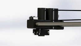
The Robo3d has a safety measure put in where when the nozzle touches the bed, the nuts will unseat from their housing so as to not put force on the bed and get "thrown" out. This is what people refer to when they " throw their nuts".
Using this principle of the nut unseating, they used a coupling nut in it's place and attached a switch to it. The switch connects to the coupling with a plastic mount. The switches then activates against the x motor carriage and the x idler respectively.
With this switch in place, as soon as the nozzle touches the bed and the couplings begin to unseat the switch will deactivate sending a signal to the ramps board that an endstop has been hit. It's used for both the Z0 sensor and the probe sensor.
How mine differs:
With my design the switches are run in series to avoid a failure situation. Were the switches to be improperly seated or a failure in the wire the RoBo3d would just raise up during it's normal z operation and not throw the nuts. Click Here to see why I ran my switches in series.
Note: If you have auto bed leveling from RoBo3D do not use my firmware without modifying your wiring
Build it
Parts List:
2x 5/16"-18 Coupling (Or M8-1.25 Coupling for those on metric rods)
2x Micro switch (1x in addition to the 1 on the Z axis)
2x M3 - 25mm
2x M3 Nuts
4x M2-10mm (2x in addition to 2 securing Z switch)
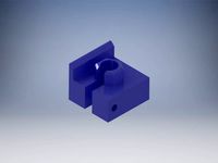
Printed Parts:
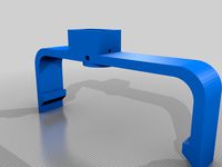
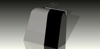
RoBo 3D auto level switch mount
Assembly:
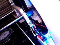
Begin by securing the switch to the mounting plastic. It's probably easiest to thread on the coupling first before securing the switch. The bracket should expand enough to go around the threaded rods.
With the mounting bracket in place secure the M3 nut and screw and begin to tighten it down, but loose enough the plastic can still slide on the coupling.
Adjust the mount distance from the idler until the switch is barely activated. The switch should activate easily when the idler presses down on it, but deactivate quickly once the coupling begins to unseat. This may take some fine tuning but once you secure it it should stay true.
Wiring:
With the switch in position it's time to do the wiring.
Current Autolevel owners:
If you have RoBo3D's Autolevel switches you can turn your parallel switches into series but it requires unsoldering from the NC leg and soldering to the NO leg. Then you trim one of the legs short (say on red) and then another one long enough to solder onto, then you modify your wiring to represent below.
New to Autolevel owners:
Follow the wiring diagram to wire your switches in position. You will most likely need to trim and solder to get the lengths needed. Color/polarity is not critical.
attachFull3240
Control It
Firmware:
With the switches wired in position it's time to change the firmware. This is the same Auto_Level firmware used by team RoBo, but modified with 1 key difference:
const bool Z_MIN_ENDSTOP_INVERTING = true;
modified to:
const bool Z_MIN_ENDSTOP_INVERTING = false;
Which is traditional.
Download the firmware below.
Use either MatterControl or Arduino software to flash the firmware.
It should also be noted this firmware will work on any RoBo 3d with or without auto-level.
Calibration:
With the firmware installed it's time to determine the Z offset between when the nozzle touches the bed and when the switches activate.
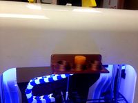
Begin by homing all axis, ensuring the Z homes in the center of the bed.
Using MC or Repetier raise the nozzle up .1mm at a time until you're able to slide a piece of paper underneath it, counting how many steps it took. Once you can barely fit the paper under, remove the paper and lower the nozzle by .1mm. This is your Z offset
Modify the G-code:
With the firmware installed it's time to configure the Gcode to run the auto-level script and calibrate the Z height. Insert this code in the starting procedures for your slicer after the G28 codes.
[code]
G1 Z0.5 ;Adjust Z offset
G92 Z0 ;Define new Z home
G29 ;Autocalibrate bed
[/code]
That should be everything there is too it. I find it helps to monitor the output from the G29 sequence in the terminal. That way if you see an unusual number you'll be able to address it quicker.
Please let me know if you have any questions
Ace Hardware sells M8-1.25mm couplings for anyone that has them locally.
Auto Bed Levelness Compensation (ABLC)
Questions and Answers:
What is Auto Bed Leveling?
Auto Bed Leveling is when the bed levelness is adjusted through mechanical action to achieve a bed that is leveled against the nozzles movement. This is not the same as ABLC
What is Auto Bed Levelness Compensation?
ABLC is the process of probing the bed with a measurement device to determine the level error of the bed and compensate for this by moving the Z axis up and down. There is no mechanical variation but rather software compensation.
Why is it referred to as Auto Bed Leveling?
Probably for simplicity sake. Hence why I titled this Autolevel. It's generally acceptable to trim words if your point is still made.
How it works:
The Robo3d has a safety measure put in where when the nozzle touches the bed, the nuts will unseat from their housing so as to not put force on the bed and get "thrown" out. This is what people refer to when they " throw their nuts".
Using this principle of the nut unseating, they used a coupling nut in it's place and attached a switch to it. The switch connects to the coupling with a plastic mount. The switches then activates against the x motor carriage and the x idler respectively.
With this switch in place, as soon as the nozzle touches the bed and the couplings begin to unseat the switch will deactivate sending a signal to the ramps board that an endstop has been hit. It's used for both the Z0 sensor and the probe sensor.
How mine differs:
With my design the switches are run in series to avoid a failure situation. Were the switches to be improperly seated or a failure in the wire the RoBo3d would just raise up during it's normal z operation and not throw the nuts. Click Here to see why I ran my switches in series.
Note: If you have auto bed leveling from RoBo3D do not use my firmware without modifying your wiring
Build it
Parts List:
2x 5/16"-18 Coupling (Or M8-1.25 Coupling for those on metric rods)
2x Micro switch (1x in addition to the 1 on the Z axis)
2x M3 - 25mm
2x M3 Nuts
4x M2-10mm (2x in addition to 2 securing Z switch)
Printed Parts:
RoBo 3D auto level switch mount
Assembly:
Begin by securing the switch to the mounting plastic. It's probably easiest to thread on the coupling first before securing the switch. The bracket should expand enough to go around the threaded rods.
With the mounting bracket in place secure the M3 nut and screw and begin to tighten it down, but loose enough the plastic can still slide on the coupling.
Adjust the mount distance from the idler until the switch is barely activated. The switch should activate easily when the idler presses down on it, but deactivate quickly once the coupling begins to unseat. This may take some fine tuning but once you secure it it should stay true.
Wiring:
With the switch in position it's time to do the wiring.
Current Autolevel owners:
If you have RoBo3D's Autolevel switches you can turn your parallel switches into series but it requires unsoldering from the NC leg and soldering to the NO leg. Then you trim one of the legs short (say on red) and then another one long enough to solder onto, then you modify your wiring to represent below.
New to Autolevel owners:
Follow the wiring diagram to wire your switches in position. You will most likely need to trim and solder to get the lengths needed. Color/polarity is not critical.
attachFull3240
Control It
Firmware:
With the switches wired in position it's time to change the firmware. This is the same Auto_Level firmware used by team RoBo, but modified with 1 key difference:
const bool Z_MIN_ENDSTOP_INVERTING = true;
modified to:
const bool Z_MIN_ENDSTOP_INVERTING = false;
Which is traditional.
Download the firmware below.
Use either MatterControl or Arduino software to flash the firmware.
It should also be noted this firmware will work on any RoBo 3d with or without auto-level.
Calibration:
With the firmware installed it's time to determine the Z offset between when the nozzle touches the bed and when the switches activate.
Begin by homing all axis, ensuring the Z homes in the center of the bed.
Using MC or Repetier raise the nozzle up .1mm at a time until you're able to slide a piece of paper underneath it, counting how many steps it took. Once you can barely fit the paper under, remove the paper and lower the nozzle by .1mm. This is your Z offset
Modify the G-code:
With the firmware installed it's time to configure the Gcode to run the auto-level script and calibrate the Z height. Insert this code in the starting procedures for your slicer after the G28 codes.
[code]
G1 Z0.5 ;Adjust Z offset
G92 Z0 ;Define new Z home
G29 ;Autocalibrate bed
[/code]
That should be everything there is too it. I find it helps to monitor the output from the G29 sequence in the terminal. That way if you see an unusual number you'll be able to address it quicker.
Please let me know if you have any questions
Ace Hardware sells M8-1.25mm couplings for anyone that has them locally.
Similar models
thingiverse
free

RoBo3D Autolevel via Mike Kelly by mkelly
...ran my switches in series.
note: if you have auto bed leveling from robo3d do not use my firmware without modifying your wiring
thingiverse
free

Mendel90 x-carriage with z probe by LarsBrubaker
...sed with new firmware (matterprint3d) your mendel90 can auto calibrate the bed height and dynamically compensate to ensure level.
thingiverse
free

calibrate z axis & auto level sensor .. by yamaren
...gher than nozzle
14mm height for nozzle , 15mm for level sensor ..
from the other side you can adjust the 2 z motors with bed ..
thingiverse
free

PrintinZ Zebra bed clips for roboed r1 plus by kingkuul
...ut saying with your new zebra bed make sure you change the g-code for the robo3d r1plus so you auto level with a cold nozzle.....
thingiverse
free
RoBo3D R1 Solenoid Auto-Leveling by mkelly
... forum post here: http://forums.robo3dprinter.com/index.php?threads/mike-kellys-solenoid-auto-level-for-stock-r1.3864/#post-34724
thingiverse
free

Robo3D: Leadnut adapter with z-axis limit switch by kabe
... and screw, able to buy from maker's tool works.
uploaded file is for right side. please mirror by your slicer for left side.
thingiverse
free

Anet A8 Heatbed protector by chriswal
...hen you run against the protector the coupler will expand. so be sure that the coupler didnt expand when the endstop is triggered
thingiverse
free
Robo3d Autolevel Z Brackets by Cyberzoid
... extra movements that's to my own preference but basically:
g28 ; home
m565 z-0.85 ; set z probe offset,
g29 ; probe the bed
thingiverse
free
Robo3D Z-Limit Switch Relocation by davie1699
...rked before i printed the other x-carriage-z-stop for x home side. it turned out to work so well i've just left it like that.
thingiverse
free

Robo R1 TR8 Lead Screw / Coupling Upgrade by WheresWaldo
... stepper.
multiple versions of the source files are included if you need to modify the dimensions slightly (step, sat & smt).
Autolevel
thingiverse
free

Autolevel by Lo_Copio_too
...autolevel by lo_copio_too
thingiverse
autolevel.
https://youtu.be/9idq1xy8i6i
thingiverse
free

Autolevel Fix by Kevinalign
...autolevel fix by kevinalign
thingiverse
to fix the bar of the optic autolevel, with a 3m screw
thingiverse
free

TronxyX5 Autolevel Holder
...tronxyx5 autolevel holder
thingiverse
tronxy x5 holder for pl-08n autolevel sensor
thingiverse
free

Silenciador de autolevel - Autolevel silencer by BFBA
...need to be corrected with a file after printing in order to work properly. the autolevel installed is a "3d touch" one.
thingiverse
free

Silenciador de autolevel - Autolevel silencer by BFBA
...need to be corrected with a file after printing in order to work properly. the autolevel installed is a "3d touch" one.
thingiverse
free

autolevel probe retractor by mming1106
...autolevel probe retractor by mming1106
thingiverse
autolevel probe retractor
thingiverse
free

easy autolevel by obdiy
...easy autolevel by obdiy
thingiverse
simple carriage for z- autoleveling
for direct-drive extruders (i use mk7/mk8)
thingiverse
free

Autolevel probe by eca3d
...robe by eca3d
thingiverse
autolevel probe for printer rostock.
description here: http://eca3d.blogspot.ru/2014/05/rostock-5.html
thingiverse
free

Autolevel Gehäuse by IW3D
...el gehäuse by iw3d
thingiverse
selbstgebauter autolevel sensor mit gehäuse mit deckel
material pla von bq orange 1.75 nozzel 0,4
thingiverse
free
Autolevel FLSUN QQ-S
...el flsun qq-s
thingiverse
autolevel switch
with https://aliexpress.ru/item/32915708033.html?spm=a2g0s.9042311.0.0.274233edtlbqkq
Robo3D
turbosquid
$2
Robo3D Feet
... available on turbo squid, the world's leading provider of digital 3d models for visualization, films, television, and games.
thingiverse
free

Robo3d Filament Guide by sjreggel
...robo3d filament guide by sjreggel
thingiverse
robo3d filament guide, to be used with the default robo3d spool holder
thingiverse
free

Robo3D USB Support by GipsyEureka
...robo3d usb support by gipsyeureka
thingiverse
robo3d usb support.
thingiverse
free

Robo3D Camera Mount by robro
...robo3d camera mount by robro
thingiverse
mount for a logitech c270 webcamto a robo3d printer
thingiverse
free
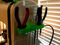
Robo3D Tool Holder by huntergrayson
...robo3d tool holder by huntergrayson
thingiverse
an out of the way place for your tools on the robo3d printer
thingiverse
free

Robo3D Top Mount by ThorMJ
...o the robo3d.
added a version with longer posts so it clears the robo3d handle from the http://www.thingiverse.com/thing:234939
thingiverse
free

Screws' holder Robo3D by GalloEnricoDesign
...screws' holder robo3d by galloenricodesign
thingiverse
a easy support used as holder for screws' extruder
for robo3d.
thingiverse
free

ROBO3D Spool Cap by portdog77
...robo3d spool cap by portdog77
thingiverse
this is a cap i made for my robo3d to hold the filliment next to the machine.
thingiverse
free
ROBO3D OILER HOLDER by Prefab
...robo3d oiler holder by prefab
thingiverse
holds your robo3d oilers so you can always find them
thingiverse
free

robo3d feet simple version by Windpower
...robo3d feet simple version by windpower
thingiverse
robo3d feet remember to print 4.
Kelly
turbosquid
$7

Kelly
...royalty free 3d model kelly for download as max, obj, and fbx on turbosquid: 3d models for games, architecture, videos. (1225855)
3ddd
free
Tacchini Kelly
...tacchini kelly
3ddd
tacchini , kelly
polys 12 676
unwrap uvw
3ddd
$1

кровать KELLY
...кровать kelly
3ddd
gamma arredamenti
мебель фабрики gamma arredamenti
кровать kelly
3ddd
$1
Декор - Kelly Hoppen
...декор - kelly hoppen
3ddd
kelly hoppen , декоративный набор
декор - kelly hoppen
design_connected
$29
Kelly Bed
...kelly bed
designconnected
poliform kelly bed computer generated 3d model. designed by gallina, emmanuel.
3ddd
$1
KELLY WEARSTLER
...kelly wearstler
3ddd
kelly wearstler
http://www.1stdibs.com/furniture_item_detail.php?id=698470
3ddd
$1

KELLY SO1
...kelly so1
3ddd
studio italia design
итальянский светильник kelly so1 сделанный по размерам
3ddd
free
Кровать KELLI. ZEGEN.
... zegen , тумба
кровать kelli. от мебельной фабрики zegen.
turbosquid
$30

KELLY armchair
...alty free 3d model kelly armchair for download as max and obj on turbosquid: 3d models for games, architecture, videos. (1508765)
3ddd
$1

Декоративный набор Kelly Hoppen
...абор kelly hoppen
3ddd
декоративный набор , kelly hoppen
декоративный набор kelly hoppen
Mike
turbosquid
$1
Mike
... available on turbo squid, the world's leading provider of digital 3d models for visualization, films, television, and games.
3d_export
$5

mike wazowski
...mike wazowski
3dexport
mike wazowski 3d model good quality for animation
3ddd
$1

busnelli mike
...busnelli mike
3ddd
busnelli
диван фабрики "busnelli",модель "mike",дизайнер marc sadler
3ddd
$1

busnelli mike
...busnelli mike
3ddd
busnelli
кресло фабрики "busnelli",модель "mike",дизайнер marc sadler
3d_export
$7

mike-the-mechanic-1snapshot4
...mike-the-mechanic-1snapshot4
3dexport
mike-the-mechanic-1.snapshot.4
turbosquid
$2

Mike Wazowzki
...squid
royalty free 3d model mike wazowzki for download as ma on turbosquid: 3d models for games, architecture, videos. (1578799)
turbosquid
$35

Mike CW
...d
royalty free 3d model mike 3d model cw for download as fbx on turbosquid: 3d models for games, architecture, videos. (1514581)
turbosquid
$43

Military Mike
... available on turbo squid, the world's leading provider of digital 3d models for visualization, films, television, and games.
turbosquid
free

mike wazowski
... available on turbo squid, the world's leading provider of digital 3d models for visualization, films, television, and games.
turbosquid
free

Mike the tv
... available on turbo squid, the world's leading provider of digital 3d models for visualization, films, television, and games.
Via
turbosquid
$20

vias
... available on turbo squid, the world's leading provider of digital 3d models for visualization, films, television, and games.
3ddd
$1
Favero / via veneto
...favero / via veneto
3ddd
favero
кровать favero модель via veneto сайт производителя www.faveromobili.it
3ddd
$1

Favero / via veneto
...
3ddd
favero , шкаф
шкаф favero модель via veneto сайт производителя www.faveromobili.it
3ddd
$1

Favero / via veneto
...ddd
favero , комод
комод favero модель via veneto сайт производителя www.faveromobili.it
3ddd
free
Favero / via veneto
... тумба
прикроватная тумба favero модель via veneto сайт производителя www.faveromobili.it
3ddd
$1
Odeon / Via
..., odeon , via
набор светильников в стиле модерн
3ddd
free

Vespa Via cosmetic
... vespa , веспа
набор косметики vespa via. буду рада увидеть его в ваших рендерах
3ddd
$1
Люстра ILLUMINATI Via Lattea
...ti , via lattea
люстра illuminati (vai lattea mx7606-5b). описание - 1*е27, d:530, h:450
turbosquid
$19

Coffee Table VIA Green
...alty free 3d model coffee table via green for download as max on turbosquid: 3d models for games, architecture, videos. (1708352)
turbosquid
$49

Versace Carpet Via Gesu
... available on turbo squid, the world's leading provider of digital 3d models for visualization, films, television, and games.