Thingiverse
Ring Lamp Dual V2 (Customizable) by geit_de
by Thingiverse
Last crawled date: 2 years, 11 months ago
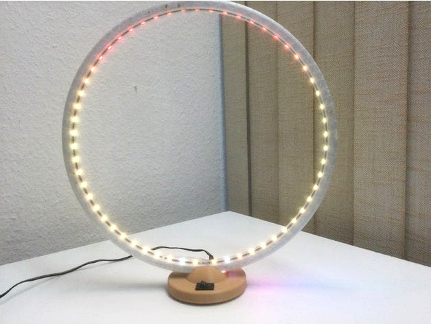
A little ring lamp with 330mm or 200mm diameter. You need a printer with around 220x220mm build plate to be able
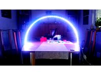
Here is a link were you can see the new version in action. The mode running is "Race".Ring Lamp V2 Race mode
Key Features:
When designing this I had some key features in mind:
° simple and clean print
° avoid the led strips glue tape on the back at all cost.
° add a simple compartment for the electronics.
° wire management
° easy to print.
° no flimsy pegs to mount, which fail printing or break away later on.
Requirements:
1x 5V power supply
1x Power Connector
1x Switch
1x LED strip. (60 pixel/m or more)
WARNING! You need a LED strip without a rubber dome. Just the plain flexible PCB with the LEDs and resistors soldered on.
I used a 60 pixel/mm strip and ended up using 118 LEDs (58/60) in total for the big version and 70 LEDs (34/36) for the smaller version. You can reduce the number of LEDs for the outer rings by two LEDs as they mostly get covered by the socket anyway.
Printing:
You need to print a the socket, the lid and four ring pieces. One of the ring segments has an opening for the wiring. The other file marked with 3x need to be printed three times.
Make sure you pick the matching files for the radius. The socket for the 100mm (R100) ring will not fit the 165mm (R165) radius sized ring and vice versa.
Another important thing: Use a raft. Yes, rafts take a while to print and eat a lot of plastic as well, but so do the ring segments and one single fail or a warped and thereby unusable ring segment wastes even more plastic. Especially when having issues with temperatures in the print bed corners, a raft saves filament and not the opposite. So adding one hour per ring segment isn't that bad compared to a total fail after 3 hours of printing. Better get it done right the first time, instead of failing several times first. Bonus effect: The ring will look more or less the same on both sides, which is great.
Build process:
Using a little glue the segments are quick attached together. When printing the ring segment using ABS you can use acetone as glue to weld the sections together.
Before gluing the bottom ring opening together, slide in the LED strip into the ring section. It is easier to solder the wires before sliding them in. The data direction of both strips should be different. So if the inner strip has the wires to the left, the right one needs them to the right. That way the effects will mix perfectly.
Also make sure to glue the side with the opening last, as this is the section where the LED strips start and end. A PCB only LED strip is required. Strips with a defusing rubber dome cover, will not work. There is an opening in the ring socket. Just add a little glue and align the wire guide opening before placing the ring into the slot of the base.
Slide in the switch and glue in the power connector, connect the ESP32 and done. This is just basic stuff. 5V to 5V, GND to GND and the inner ring light data line to pin G23 of the ESP. The outer rings LED strip data line needs to be connected to pin G22.
You can use any kind of software to drive the ring lamps LED strip. Even use an Arduino and some example code.
There is an archive containing the source code included. Please check the read me file for further details.
I made a video to show the build process more or less in detail.
https://www.youtube.com/watch?v=G0Ccoee1Y5A
Language is German, so be warned. :D The video is also for the revision 1 of the ring, but beside minor changes the assembly is mainly the same.
Current Features:
° web interface
° OTA update support
° flash fs settings support
° LED color and temperature correction
° 12 effects (static, rainbow, fire place, RGB fader, ...)
° optional sound support (hour/30 min gong) (requires DFPlayer sound module)
° timed power mode: The ring lamp turns on and off at a specific hours.
° timed dimming mode: The ring lamp changes brightness at specific hours.
° timed sound mode: The ring lamp changes volume at specific times.
° Full fledged Alexa support.
° Optional button support for quick on/off/audio switch.
Customize:
To customize the ring you need at least FreeCAD 0.19.1 or up. The model is fully parametric and you should be able to modify stuff like the size of the opening for the switch by just tweaking the spreadsheet. Of course this also works for all other dimensions.
Parts:
I changed the default design to use a standard toggle switch which can be found on coffee makers.
For the power inlet I used a power jack adapter You find them on internet routers, USB hubs, scanners and other low power devices.
I usually salvage these parts before throwing old hardware away, so I have a bunch of them. The power connector is not optimal, but looks nice, when glued into the base. As said the model is customizable, so you can use what ever you have at hand.
If you want to use something different, just change the width and height values inside the spreadsheet.
Updates:
11.06.2021:
° RingLamp-Quarter_R165_Dual3x.obj was wrong. Thanks to BlackOmega368 for reporting this.
° Added additional sockets without the switch pocket.
° Released Firmware V1.29
12.06.2021
° RingLamp-Quarter_R100_Dual1x.obj needed a bigger cable guide opening.
Final Words:
If there are any questions feel free to write a comment. Please post a make, so people can see my model really works and I get positive feedback in the same process, too.
Currently the software is missing. I will release an update shortly. You can use the software version from V1, but it of course will only drive the inner LED strip. In the future the same firmware will be suitable for both version.
Similar models
thingiverse
free

Ring Lamp (Customizable) by geit_de
...rubber dome cover, will not work. there is a similar opening in the ring socket. just add a little...
thingiverse
free

Printed LED Desk lamp by Promocable
...he wires from the led strips
final assemble screwing the printed parts together
done -> profit
i apologize for my englisch. :/
thingiverse
free

Articulating LED Strip Lamp by Mossball765
...g around. regular single colour led strips can be used as well.
1x 12v 5a power supply
edit 2020-11-03
added the missing knob stl
grabcad
free

Solderless led ring lamp for 3d printing
...ou wish.
a ringlamp for portrait/macro photography.
adjustable height for most lenses.
print deflector with translucent plastic.
thingiverse
free

Moon lamp base and stand for LED light by paulkoan
... have +12v, then rgb pads to ground. i soldered ground across all three pads, and wired this to a switch and a 12v power supply.
thingiverse
free
Led Arc Lamp by Niyada
...and
the surrounding area)
in one of the feet is a hole for a potentiometer, one for a power source and one for the led connectors
thingiverse
free

Another Circular Lamp by mistic100
...wice.
mode 0 : not configurable
mode 1 : long touch to change the temperature
mode 2 : not configurable
mode 3 : not configurable
thingiverse
free
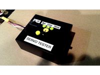
Servo Tester Case by MakerDan55
...switch on the top).
plug in a servo and test it out!
i sanded and spray painted my case to get rid of the rough plastic surface.
thingiverse
free

Pi Camera Light for Harbor Freight "200 Lumen LED Super Bright Flip Light" by mer2329
...and it all works.
once i finish (my glue is drying (i used e6000, and that takes a day to cure)) i will take photos and post them
cults
free

Led bridge lamp PSU covers
... separate 5v / 20a power supply for it and there is the covers for it. they provide good ventilation, sockets and on/off switch.
Geit
thingiverse
free

GeitPrinter by geit_de
...(magnetic parking)
2x m3 15mm counter sunk enclosure screws (e3dv6 fan)
8x 4mm cubic neodymium magnets (magnetic parking)
3dwarehouse
free

model houdertje voor in geit
...model houdertje voor in geit
3dwarehouse
model houdertje voor in geit
3dwarehouse
free

Playground skip goat _Wip geit toestel
...playground skip goat _wip geit toestel
3dwarehouse
3dwarehouse
free

Geit Kip en Konijnenhok voor open verblijf
...geit kip en konijnenhok voor open verblijf
3dwarehouse
hok geschikt voor 2-3 dwergeitjes tot 50-60 cm 3-4 konijnen 3-5 kippen
3dwarehouse
free
Goat
...goat 3dwarehouse goat geit 3d geit 3d goat...
3dwarehouse
free
estonian 'my home'
...'my home' 3dwarehouse its my home in estonia autor geit griin #estonia #gonsiori...
3dwarehouse
free

Stal / Barn
...invented it myself. #barn #boerderij #cow #cows #farm #geit #geitn #hok #koe #koeien #schaap #schapen #sheep...
3dwarehouse
free
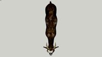
Ibex (adult male)
...steep regions to avoid predators. #animal #beast #beest #dier #geit #goat #ibex #mammal #mountain...
3dwarehouse
free
schaap
...leveren. het is een herkauwer, nauw verwant met de geit de soort behoort tot het geslacht ovis, waar ook...
Customizable
3d_export
$10
customizable sd port
...customizable sd port
3dexport
customizable sd port
turbosquid
$99

Customizable character
...alty free 3d model customizable character for download as max on turbosquid: 3d models for games, architecture, videos. (1152525)
turbosquid
$1

Customizable Mug
... available on turbo squid, the world's leading provider of digital 3d models for visualization, films, television, and games.
turbosquid
$1
Customizable Spider Mech
... free 3d model customizable spider mech for download as blend on turbosquid: 3d models for games, architecture, videos. (1462055)
turbosquid
$20
Customizable Egyptian Pillar
...zable egyptian pillar for download as ma, obj, fbx, and blend on turbosquid: 3d models for games, architecture, videos. (1307376)
turbosquid
$75
Fully Customizable Hospital
... available on turbo squid, the world's leading provider of digital 3d models for visualization, films, television, and games.
turbosquid
$20

Customizable Caste Pieces
... available on turbo squid, the world's leading provider of digital 3d models for visualization, films, television, and games.
turbosquid
$15
Customizable Tea Cup
... available on turbo squid, the world's leading provider of digital 3d models for visualization, films, television, and games.
turbosquid
free
Water Bottle(Customizeable)
... available on turbo squid, the world's leading provider of digital 3d models for visualization, films, television, and games.
3d_export
$49
Book customizable 3D Model
...3dexport
book booshelf novel teach library learn read pages cover fairy tales
book customizable 3d model guitargoa 74240 3dexport
Dual
turbosquid
free

Dual Pistols
...ls
turbosquid
free 3d model dual pistols for download as fbx on turbosquid: 3d models for games, architecture, videos. (1320360)
turbosquid
$2
Dual Axe
...urbosquid
royalty free 3d model dual axe for download as fbx on turbosquid: 3d models for games, architecture, videos. (1332372)
turbosquid
$10
Dual Lesaths
... available on turbo squid, the world's leading provider of digital 3d models for visualization, films, television, and games.
3ddd
$1
плитка Dual Bianco (Испания)
...й плитки venis dual (испания). технические качества: устойчивость к стирания, отличная геометрия, отсутствие проблем при укладке.
turbosquid
$35

Dual Mesh Fonts
...ree 3d model dual mesh fonts for download as ma, obj, and fbx on turbosquid: 3d models for games, architecture, videos. (1352989)
turbosquid
$29

Dual Flask with Bungs
...del dual flask with bungs for download as obj, fbx, and blend on turbosquid: 3d models for games, architecture, videos. (1210512)
turbosquid
$19
Dual Socket Plug
...3d model dual socket plug for download as obj, fbx, and blend on turbosquid: 3d models for games, architecture, videos. (1303912)
turbosquid
$13
Dual Adjustable Pulley
... available on turbo squid, the world's leading provider of digital 3d models for visualization, films, television, and games.
turbosquid
$10
Amoi N809 Dual
... available on turbo squid, the world's leading provider of digital 3d models for visualization, films, television, and games.
turbosquid
$5
Dual Turret Tank
... available on turbo squid, the world's leading provider of digital 3d models for visualization, films, television, and games.
V2
3d_export
free
Lamp v2
...lamp v2
3dexport
lamp v2 with solar panel
3d_export
$5

hammerhead v2
...hammerhead v2
3dexport
razer hammerhead v2 headphones, modeled in cinema 4d, render in corona
3d_export
$5

manometer v2
...manometer v2
3dexport
3d_export
$5
potato v2
...potato v2
3dexport
turbosquid
$52
Lifebuoys v2
...squid
royalty free 3d model lifebuoys v2 for download as fbx on turbosquid: 3d models for games, architecture, videos. (1560870)
turbosquid
$2

Mask v2
...turbosquid
royalty free 3d model mask v2 for download as stl on turbosquid: 3d models for games, architecture, videos. (1527741)
turbosquid
free
Flashlight V2
...d
free 3d model flashlight v2 for download as , obj, and fbx on turbosquid: 3d models for games, architecture, videos. (1663559)
turbosquid
$29
Thanos v2
...
royalty free 3d model thanos v2 for download as ztl and obj on turbosquid: 3d models for games, architecture, videos. (1651077)
turbosquid
$29
Titan v2
...d
royalty free 3d model titan v2 for download as ztl and obj on turbosquid: 3d models for games, architecture, videos. (1540228)
turbosquid
$29
Frieza v2
...
royalty free 3d model frieza v2 for download as ztl and obj on turbosquid: 3d models for games, architecture, videos. (1701238)
Lamp
archibase_planet
free
Lamp
...lamp
archibase planet
lamp reading lamp table lamp
lamp - 3d model (*.gsm+*.3ds) for interior 3d visualization.
archibase_planet
free
Lamp
...lamp
archibase planet
lamp reading lamp table lamp
lamp - 3d model (*.gsm+*.3ds) for interior 3d visualization.
archibase_planet
free

Lamp
...lamp
archibase planet
lamp table lamp reading lamp
lamp - 3d model (*.gsm+*.3ds) for interior 3d visualization.
archibase_planet
free

Lamp
...lamp
archibase planet
lamp table lamp reading lamp
lamp - 3d model (*.gsm+*.3ds) for interior 3d visualization.
archibase_planet
free
Lamp
...lamp
archibase planet
lamp reading lamp table lamp
lamp - 3d model (*.gsm+*.3ds) for interior 3d visualization.
archibase_planet
free
Lamp
...lamp
archibase planet
lamp reading lamp table lamp
lamp - 3d model (*.gsm+*.3ds) for interior 3d visualization.
archibase_planet
free
Lamp
...lamp
archibase planet
lamp table lamp reading lamp
lamp - 3d model (*.gsm+*.3ds) for interior 3d visualization.
archibase_planet
free

Lamp
...lamp
archibase planet
lamp table lamp reading lamp
lamp - 3d model (*.gsm+*.3ds) for interior 3d visualization.
archibase_planet
free
Lamp
...lamp
archibase planet
lamp reading lamp table lamp lantern
lamp - 3d model (*.3ds) for interior 3d visualization.
3d_ocean
$6

Lamp
...lamp
3docean
lamp
a high quality lamp.
Ring
3d_export
$5
ring
...ring
3dexport
ring
3d_export
free

ring
...ring
3dexport
ring
3d_export
free

ring
...ring
3dexport
ring
3d_export
free

ring
...ring
3dexport
ring
3d_export
$10
ring
...ring
3dexport
lord of the rings
3d_export
$5

ring
...ring
3dexport
golden ring
3d_export
free
ring
...ring
3dexport
cherub ring
3d_export
$10
ring
...ring
3dexport
3d ring model
3d_export
$5
ring
...ring
3dexport
ring 3d model
3d_export
$5

ring
...ring
3dexport
ring top black...