Thingiverse
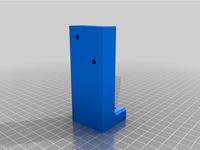
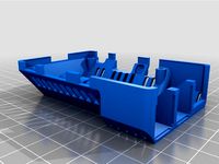
REMIX Raspberry Pi 4B case for CR6 Max with 40mm Fan and Onboard Power and Converters by cghildreth
by Thingiverse
Last crawled date: 3 years ago
First, thanks to Olvin for the design and including an editable file for remixes. Following suit, I've included the f360 files for further remixing if desired.
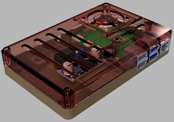
I wanted an all-in-one solution for my CR6 Max to incorporate a Raspberry Pi 4b for octoprint with a quiet fan, included usb power for the Pi and a buck converter for 12v fan (which I had lying around).
The case is pretty self explanatory. You'll need:
2x M2.5 6mm long screws to mount the R Pi
2x M2.5 25mm long screws and 2x M2.5 20mm long screws to connect the fan cover to the electronics portion of the case (the 25mm long screws go through the R Pi mounting holes
4x M3 8mm long screws to mount the buck converter and LED voltmeter
3x M4 x 8mm long screws with t nuts to mount the case to the 4040 extrusion
LM2596 Buck converter for 12v power to the fan - make sure to adjust the power output before connecting the fan! (These: https://smile.amazon.com/gp/product/B07VVXF7YX/ref=ppx_yo_dt_b_asin_title_o06_s00?ie=UTF8&psc=1 )
USB buck converter (make sure it can handle 24v incoming power) (These: https://smile.amazon.com/gp/product/B087RHWTJW/ref=ppx_yo_dt_b_asin_title_o02_s00?ie=UTF8&psc=1 )
LED Voltmeter (These: https://smile.amazon.com/gp/product/B00YALV0NG/ref=ppx_yo_dt_b_asin_title_o05_s00?ie=UTF8&psc=1 )
RPi 4b with Octoprint installed
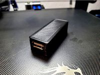
A USB voltage disconnect (I used the one I designed here: https://www.thingiverse.com/thing:4762791 )
Wire to connect to the Meanwell Power supply. I used a standard LED lighting connector for power input to the case, and rigged up a wire to the PSU. I terminated the Pi side with a standard LED power connector and the supply side with terminals.
A jst connector set for the fan connection.
A right angle connector for the USB port and a short USB C Cable (This: https://smile.amazon.com/gp/product/B08P18HKYF/ref=ppx_yo_dt_b_asin_title_o02_s00?ie=UTF8&psc=1 and this: https://smile.amazon.com/gp/product/B08D9SB161/ref=ppx_yo_dt_b_asin_title_o02_s00?ie=UTF8&psc=1 )
A 40x10mm fan, preferably very quiet. I used a Noctua 40x10 that I had laying around.
Some basic soldering skills.
Refer to the pictures for how I wired everything. Undertake this project at your own risk. If you screw this up, you could fry your boards, cause a fire, electrocute yourself, etc.
I printed the files using my CR6 Max.
I wanted an all-in-one solution for my CR6 Max to incorporate a Raspberry Pi 4b for octoprint with a quiet fan, included usb power for the Pi and a buck converter for 12v fan (which I had lying around).
The case is pretty self explanatory. You'll need:
2x M2.5 6mm long screws to mount the R Pi
2x M2.5 25mm long screws and 2x M2.5 20mm long screws to connect the fan cover to the electronics portion of the case (the 25mm long screws go through the R Pi mounting holes
4x M3 8mm long screws to mount the buck converter and LED voltmeter
3x M4 x 8mm long screws with t nuts to mount the case to the 4040 extrusion
LM2596 Buck converter for 12v power to the fan - make sure to adjust the power output before connecting the fan! (These: https://smile.amazon.com/gp/product/B07VVXF7YX/ref=ppx_yo_dt_b_asin_title_o06_s00?ie=UTF8&psc=1 )
USB buck converter (make sure it can handle 24v incoming power) (These: https://smile.amazon.com/gp/product/B087RHWTJW/ref=ppx_yo_dt_b_asin_title_o02_s00?ie=UTF8&psc=1 )
LED Voltmeter (These: https://smile.amazon.com/gp/product/B00YALV0NG/ref=ppx_yo_dt_b_asin_title_o05_s00?ie=UTF8&psc=1 )
RPi 4b with Octoprint installed
A USB voltage disconnect (I used the one I designed here: https://www.thingiverse.com/thing:4762791 )
Wire to connect to the Meanwell Power supply. I used a standard LED lighting connector for power input to the case, and rigged up a wire to the PSU. I terminated the Pi side with a standard LED power connector and the supply side with terminals.
A jst connector set for the fan connection.
A right angle connector for the USB port and a short USB C Cable (This: https://smile.amazon.com/gp/product/B08P18HKYF/ref=ppx_yo_dt_b_asin_title_o02_s00?ie=UTF8&psc=1 and this: https://smile.amazon.com/gp/product/B08D9SB161/ref=ppx_yo_dt_b_asin_title_o02_s00?ie=UTF8&psc=1 )
A 40x10mm fan, preferably very quiet. I used a Noctua 40x10 that I had laying around.
Some basic soldering skills.
Refer to the pictures for how I wired everything. Undertake this project at your own risk. If you screw this up, you could fry your boards, cause a fire, electrocute yourself, etc.
I printed the files using my CR6 Max.
Similar models
thingiverse
free

DC Buck Converter Case (eBoot)
...er supply step down module.
https://smile.amazon.com/gp/product/b01gj0sc2c/ref=ppx_yo_dt_b_asin_title_o01_s00?ie=utf8&psc=1
thingiverse
free

Lighted Curved Lithophane Box with Switch by Handler5785sd
...1
powered by 12 v transformer https://smile.amazon.com/gp/product/b01hcrugpw/ref=ppx_yo_dt_b_asin_title_o00_s00?ie=utf8&psc=1
thingiverse
free

Raspberry 4B Nextcloud
...00? ie = utf8 & psc = 1
ssd: https://www.amazon.de/gp/product/b07hncwcnl/ref=ppx_yo_dt_b_asin_title_o02_s00?ie=utf8&psc=1
thingiverse
free

NAS Raspberry Pi 4 by Romaricovert
..._title_o02_s00?ie=utf8&psc=1
https://www.amazon.fr/gp/product/b01lxrwwb6/ref=ppx_yo_dt_b_asin_title_o02_s01?ie=utf8&psc=1
thingiverse
free

Ender 3 Bucky USB power
...re pretty cheap off amazon: https://smile.amazon.co.uk/gp/product/b07xt8v97y/ref=ppx_yo_dt_b_asin_title_o01_s00?ie=utf8&psc=1
thingiverse
free
Buck Converter Case by Benvolio28
...ly.
i used this buck converter: https://www.amazon.com/gp/product/b01hm12n2c/ref=ppx_yo_dt_b_asin_title_o00_s00?ie=utf8&psc=1
thingiverse
free

Artillery Sidwinder X1 - Rasbperry Pi & StepDownConverter Mount
...ie=utf8&psc=1
usb power cable:https://www.amazon.de/gp/product/b07k1qr2k9/ref=ppx_yo_dt_b_search_asin_title?ie=utf8&psc=1
thingiverse
free

Tally Light by iotaxiii
...p;psc=1
pcb / solder breadboard: https://www.amazon.com/gp/product/b07zytz48n/ref=ppx_yo_dt_b_search_asin_title?ie=utf8&psc=1
thingiverse
free

Buck Converter Case by Stuffmeister217
...ust the voltage. this is a work in progress, the holes may not line up exactly for adjustment.
put together using 4-40x3/8 screws
thingiverse
free

Underdesk Oculus Rift CV1 Quick Connect by dkpaladin
...itle_o01_s00?ie=utf8&psc=1
https://smile.amazon.com/gp/product/b07rqrmgkb/ref=ppx_yo_dt_b_search_asin_title?ie=utf8&psc=1
Cghildreth
thingiverse
free
Monumental Figurine Bases by cghildreth
... print these in whatever colors you want to use.
this model is not licensed for commercial reproduction. use at your own risk.
thingiverse
free
Remix - Adjustable bed for K40 on a budget by Ariehh by cghildreth
...redit to ariehh. original thing is found here: https://www.thingiverse.com/thing:3965391
print with supports from the bed only.
thingiverse
free

Schlage Lever Handle Lock Plug Follower by cghildreth
...andles. rather than waiting a few days for a commercial tool to come in, i spent 10 minutes designing this and an hour printing.
thingiverse
free

Micro USB Voltage Isolator by cghildreth
...t or you risk melting the plug. use one of the many pinout diagrams that are available to match the plug pins to the board pads.
thingiverse
free
CR-6 Left Side Screen Mount and End Cap Cover by cghildreth
... and m5x8mm cap screws for the extrusion end-cap cover.
obviously, you'll have to re-route the screen cable to the left side.
thingiverse
free

CR6 Max PSU Dual 80mm Fan Cover - MeanWell RSP-500-24 by cghildreth
...he psu due to the capacitors. if you screw this up, you could die, fry your fans, fry your psu, fry your other electronics, etc.
thingiverse
free

CR6 Cable Chain Including Filament Guide and PTFE Guide by cghildreth
...on the cr6 max.
**edit: turn the link that attaches to the x-end carriage backwards so that it folds in when the x axis homes.
Cr6
3ddd
$1

Baga Emotional style CR6
...baga emotional style cr6
3ddd
baga
надеюсь кому-то пригодится :)
3ddd
$1

Светильник Baga
...3ddd baga , contemporary светильник подвесной ф. baga арт. cr6 ...
sketchfab
$50

Body CR6 Buggy
...ody cr6 buggy.
model developed for 3d print.
parts with fittings. - body cr6 buggy - buy royalty free 3d model by andreyraphael3d
thingiverse
free

Accessoire pour CR6 by jjfr
...accessoire pour cr6 by jjfr
thingiverse
pièce pour cr6 se
thingiverse
free

Cr6 Endstop With cable clip by RebelMD
...cr6 endstop with cable clip by rebelmd
thingiverse
cr6 endstop
thingiverse
free

CR6 SE Connector by p3ab0dy
... se connector by p3ab0dy
thingiverse
added a holder for the cr6 se arm. it slides in to the filament arm delivered with printer.
thingiverse
free
CR6-SE Handle by Arvi_G
...cr6-se handle by arvi_g
thingiverse
simple handle for cr6-se
requires longer m3 screw & nut to mount.
unity_asset_store
$15

SF Dreadnought CR6
...your workflow with the sf dreadnought cr6 asset from cgpitbull. find this & other space options on the unity asset store.
thingiverse
free

CR6-SE Tool Organizer by Taskino
...cr6-se tool organizer by taskino
thingiverse
a tool organizer for the creality cr6-se
thingiverse
free

CR6-SE Pi Mount by Baz_8755
...cr6-se pi mount by baz_8755
thingiverse
my first attempt at a raspbery pi mount for the creality cr6-se
4B
3ddd
$1
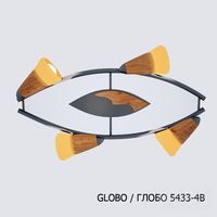
GLOBO 5433-4B
...globo 5433-4b
3ddd
globo
модель светильника globo глобо 5433-4b
turbosquid
$25

Street light 4b
... available on turbo squid, the world's leading provider of digital 3d models for visualization, films, television, and games.
3d_export
$10

Overgrown Lamp Post 4B
...overgrown lamp post 4b
3dexport
turbosquid
$32

V-2 A-4B missile
... available on turbo squid, the world's leading provider of digital 3d models for visualization, films, television, and games.
turbosquid
$18

Viking Stove VGIC245-4B 24
...ng stove vgic245-4b 24 for download as max, 3ds, fbx, and obj on turbosquid: 3d models for games, architecture, videos. (1698000)
3ddd
$1

The Zara Collection from Feiss
...no.: f2736/4bs 4-light cnandelier no.: f2745/4bs 4-light cnandelier no.: f2737/4b в архиве 3 модели, 2011 и 2014...
3d_export
$41

V2 A4B missile 3D Model
...tic missile sounding rocket experimental weapon military program surface srbm
v2 a4b missile 3d model visualmotion 86520 3dexport
3d_export
$99

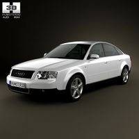
Audi A6 saloon C5 2001 3D Model
...saloon c5 2001 3d model 3dexport audi a6 c5 4b 1997 1998 1999 2000 2001 2002 2003 2004 4-door...
3d_export
$99

Audi A6 avant C5 2001 3D Model
...avant c5 2001 3d model 3dexport audi a6 c5 4b 1997 1998 1999 2000 2001 2002 2003 2004 5-door...
3d_ocean
$89
Audi A6 saloon (C5) 2001
...audi a6 saloon (c5) 2001 3docean 1997-2004 4-door 4b a6 audi audi a6 c5 germany saloon sedan volkswagen...
Onboard
3d_export
$60
mil mi-35 hind
...range finder/targeting system, glonass/gps navigation system, electronic multifunction displays, onboard computer, and jam-proof communications equipment.[11] also known as mi-35m1....
3d_export
$20

spacecraft glonass-k
...on the basis of the unpressurized platform "express 1000". onboard equipment is installed on the body in the form...
3d_export
$35

Airplane interior 3 in 1
...v: 405717, f:988076<br>passanger v:960390, f:925268<br>kitchen v:200860, f:193598<br>3d model included :<br>onboard aircraft kitchen.<br>passenger compartment.<br>cabin for two pilots. aircraft interior is...
3d_export
$5
star wars naboo n1 starfighter
...as a power charger collector, and received energy from onboard generators when it was not in use. the ships...
3d_export
$20
uss gerald
...elevators,<br>3 air lifts, the presence of different types of compartments.<br>onboard 8 su54 aircraft.<br>dimensions of an aircraft carrier:<br>length: 337m<br>width: 41-78m<br>height:...
3d_export
$12

freighter hyperion class tanker vessel
...out to claim their bounty. with 18 massive tanks onboard it is capable of delivering huge amounts of oil,...
3d_export
$12
freighter arion class cargo vessel
...pirates out to claim their bounty. with 16 containers onboard & 3 huge tanks it is capable of delivering...
3d_export
$15

Airborne Early Warning and Control
...to its supercarriers to protect them and augment their onboard command information centers (cics). the designation airborne early warning...
3d_export
$500

us navy pcu sterett ddg-104 arleigh burke class destroyer flight iia max
...drawing from the actual ship. texture maps are taken onboard the actual ship as well. all thumbnails are rendered...
thingiverse
free

Onboard Sign by KySyth
...onboard sign by kysyth
thingiverse
onboard side
saw a stupid sign and decided to make one
Raspberry
3d_export
free

raspberry
...raspberry
3dexport
3d model of a raspberry. i tried to make it realistic.
turbosquid
$27
Raspberries
...y free 3d model raspberries for download as max, obj, and stl on turbosquid: 3d models for games, architecture, videos. (1354176)
turbosquid
$14
Raspberries
...y free 3d model raspberries for download as max, obj, and fbx on turbosquid: 3d models for games, architecture, videos. (1364663)
3d_export
$5
raspberry pi
...raspberry pi
3dexport
carcasa para la raspberry pi
turbosquid
$99
Raspberry
... available on turbo squid, the world's leading provider of digital 3d models for visualization, films, television, and games.
turbosquid
$10

raspberries
... available on turbo squid, the world's leading provider of digital 3d models for visualization, films, television, and games.
archive3d
free

Raspberries 3D Model
...raspberries 3d model archive3d raspberries raspberry raspberries n300911 - 3d model (*.3ds) for interior 3d...
3d_export
$5

raspberry fruit
...raspberry fruit
3dexport
3d_export
$5

raspberry
...y different sizes. their color ranges from light burgundy to pink. there are formats: obj, 3ds, blend, dae, fbx, mtl.<br>:)
evermotion
$12

raspberries 23 am130
...evermotion raspberries 23 am130 evermotion key 23 food fruit raspberry fruits am130 raspberries highly detailed 3d model of raspberries...
40Mm
turbosquid
$10

40MM Bullet
... available on turbo squid, the world's leading provider of digital 3d models for visualization, films, television, and games.
turbosquid
$49
40mm Vickers-Terni
... free 3d model 40mm vickers-terni for download as lwo and obj on turbosquid: 3d models for games, architecture, videos. (1260063)
turbosquid
$3
40mm grenade M9XX
...y free 3d model 40mm grenade m9xx for download as obj and fbx on turbosquid: 3d models for games, architecture, videos. (1408150)
turbosquid
$3

40mm grenade M3XX
...y free 3d model 40mm grenade m3xx for download as obj and fbx on turbosquid: 3d models for games, architecture, videos. (1408145)
turbosquid
$3
40mm grenade M1XX
...y free 3d model 40mm grenade m1xx for download as obj and fbx on turbosquid: 3d models for games, architecture, videos. (1408144)
turbosquid
$8

40mm Smith & Wesson
... available on turbo squid, the world's leading provider of digital 3d models for visualization, films, television, and games.
turbosquid
free
Free 40mm grenade M433
...e 3d model free 40mm grenade m433 for download as obj and fbx on turbosquid: 3d models for games, architecture, videos. (1404768)
turbosquid
$98

40mm 6G30 grenade launcher
... available on turbo squid, the world's leading provider of digital 3d models for visualization, films, television, and games.
turbosquid
$10

Famas G2 M203 40mm.
... available on turbo squid, the world's leading provider of digital 3d models for visualization, films, television, and games.
turbosquid
free
40mm Bofors TNT-11606
... available on turbo squid, the world's leading provider of digital 3d models for visualization, films, television, and games.
Pi
design_connected
$11
Pi
...pi
designconnected
ligne roset pi chairs computer generated 3d model. designed by thibault desombre.
3d_export
$5
raspberry pi
...raspberry pi
3dexport
carcasa para la raspberry pi
turbosquid
$18
pied
... available on turbo squid, the world's leading provider of digital 3d models for visualization, films, television, and games.
3ddd
$1
Emme pi light
...emme pi light
3ddd
emme pi light
люста emme pi light
3ddd
$1
Emme pi light
...emme pi light
3ddd
emme pi light
бра классическое emme pi light
3ddd
$1
Emme Pi Light
...emme pi light
3ddd
emme pi light
3ddd
$1

Emme Pi Light
...emme pi light
3ddd
emme pi light
design_connected
$16
Pi-Air
...pi-air
designconnected
living divani pi-air lounge chairs computer generated 3d model. designed by harry & camila.
3d_ocean
$15
Manneken Pis
...picting a naked little boy urinating into a fountain’s basin. (wikipedia) the model was sculpted in blender 2.70a rendered wit...
3ddd
$1
Emme pi light
...emme pi light
3ddd
emme pi light
люстра классическая фирма: emme pi light
артикул: 3595/5/cot/12/wh
Converters
turbosquid
free
pallet converter
...d
royalty free 3d model pallet converter for download as rfa on turbosquid: 3d models for games, architecture, videos. (1285733)
3d_ocean
$85

Convertible Porsche
...agon
3d model of convertible porsche .object are grouped.rendering scene with,materials are include and detailed, with all files.
turbosquid
$5

GPU Converter
...yalty free 3d model gpu converter for download as 3ds and max on turbosquid: 3d models for games, architecture, videos. (1355494)
turbosquid
$14

Convert Sofa
... 3d model convert sofa for download as max, 3ds, fbx, and obj on turbosquid: 3d models for games, architecture, videos. (1546663)
3d_export
$15

pontiac gto convertible
...pontiac gto convertible
3dexport
pontiac gto convertible 3d model.
turbosquid
$10

Converter station
... available on turbo squid, the world's leading provider of digital 3d models for visualization, films, television, and games.
3d_ocean
$89
Audi A5 Convertible
...erman german interior interior luxury luxury sport sport vehicle vehicle
audi a5 convertible – high detailed model with interior.
3d_ocean
$55

Convertible Car
...d model of convertible car .objects are grouped.rendering scene with texture,materials are included and detailed, with all files.
3d_ocean
$89

Audi S5 Convertible
... german interior interior luxury luxury s5 s5 sport sport vehicle vehicle
audi s5 convertible – high detailed model with interior
design_connected
$27

Nomade Convertible Sofa
...ade convertible sofa
designconnected
ligne roset nomade convertible sofa computer generated 3d model. designed by gomez, didier.
Fan
3d_export
$5

fan
...fan
3dexport
fan 3d model, table fan, fan, electric fan, ventilator
archibase_planet
free

Fan
...fan
archibase planet
fan large fan
fan out n260707 - 3d model for interior 3d visualization.
archibase_planet
free
Fan
...fan
archibase planet
fan ceiling fan ventilator
fan stealth n300615 - 3d model (*.gsm+*.3ds) for interior 3d visualization.
3d_export
$15

fan
...fan
3dexport
is an ancient fan
3ddd
$1
Fan-C-Fan by marco gallegos
...n-c-fan by marco gallegos
3ddd
вентилятор , marco gallegos
fan-c-fan by marco gallegos
3d_export
$10
fan
...fan
3dexport
a detailed fan designed for home or space blowing is now available for only 19.99!
turbosquid
$1
Fan
...fan
turbosquid
free 3d model fan for download as on turbosquid: 3d models for games, architecture, videos. (1427865)
turbosquid
$14
Fan
...fan
turbosquid
royalty free 3d model fan for download as on turbosquid: 3d models for games, architecture, videos. (1415642)
3ddd
$1

Светильник Fan
...светильник fan
3ddd
fan , italamp
светильник fan, производитель italamp
turbosquid
$25

Fan
...fan
turbosquid
royalty free 3d model fan for download as c4d on turbosquid: 3d models for games, architecture, videos. (1483246)
Remix
turbosquid
$5
MODA Collection Remix Chair
... available on turbo squid, the world's leading provider of digital 3d models for visualization, films, television, and games.
3d_export
$12

remix yamaha rm1x
...remix yamaha rm1x
3dexport
geometry triangles 15.2k vertices 7.6k pbr no textures 1 materials 1 uv layers yes
3d_ocean
$5
Vray fabric Kvadrat remix green - tileable
...th vray and 3dsmax. high-resolution texture images (2000×2000 px) file included: shader vray 2.40 texture image 3ds max 2011 file
turbosquid
$20
Gerrit Rietveld 1938 Zig Zag Chair Remix
... available on turbo squid, the world's leading provider of digital 3d models for visualization, films, television, and games.
3d_export
$10

multicolored remix parametric table furniture
... fbx, obj, mtl, archive with textures. the model has no glitches. render and materials - vray . without using plugins. good use!
3ddd
$1
Barovier&Toso / Manhattan Remix 7192
... 004293-142405
в коллекции есть люстры 7, 9, 12 рожковые. диаметр соответственный 1000, 1250, 1500 мм.
3ddd
$1
Muuto fiber chair
...grey/grey, dusty green/dusty green, nature/oak, natural white/oak upholstery options remix 183/black, remix 133/grey, remix 643/dusty red leather options black...
3ddd
$1
Barovier&Toso 7190-7195
...7190-7195 3ddd barovier&toso потолочнай люстра фабрики barovier&toso;, коллекция manhattan remix артикул 7190-7195. размеры в inches: 39"...
3d_export
$5
3D Locking Handle Weatherproof Storage Box Container
...handle weatherproof storage box container 3dexport new, improved and remixd! no screws required. print-in-place. weatherproof. parametric. 2 parts. easy...
cg_studio
$49
HTC One Mini 2 Amber Gold3d model
...cell phone mobile cellular super lcd touchscreen touch screen remix amber gold .max .obj .mb .lwo .fbx .c4d .3ds...
Power
turbosquid
$100
power
...ower
turbosquid
royalty free 3d model power for download as on turbosquid: 3d models for games, architecture, videos. (1421990)
3d_export
$5

Power
...power
3dexport
3d_export
$5
power outlets
...power outlets
3dexport
power outlets
3ddd
$1
lion power
...lion power
3ddd
лев , статуя
lion power gold sculpture
3ddd
$1
Sea Power
...
компас , море , часы
часы с компасом sea power
3ddd
free
Meridiani / Power
...power
3ddd
meridiani , круглый
стол power производитель meridiani, диаметр 120,высота 67
3d_export
$5

Power Surge
...power surge
3dexport
the power surge is a all mesh carnival ride to lower in game part count and lag
turbosquid
$8
Airport Ground Power Unit (AXA Power )
... available on turbo squid, the world's leading provider of digital 3d models for visualization, films, television, and games.
turbosquid
$50

Power Houser
...rbosquid
royalty free 3d model power houser for download as on turbosquid: 3d models for games, architecture, videos. (1333800)
3d_export
$5

power outlet
...power outlet
3dexport
power outlet<br>format file maya 2018, 3d max 2017, obj, fbx
Case
3d_export
$1
case
...case
3dexport
case
archibase_planet
free
Case
...case
archibase planet
showcase show-case glass case
glass-case + cakes - 3d model for interior 3d visualization.
archibase_planet
free
Case
...case
archibase planet
showcase show-case glass case
glass-case for chips - 3d model for interior 3d visualization.
archibase_planet
free
Case
...case
archibase planet
case shelving drawer
case - 3d model for interior 3d visualization.
archibase_planet
free
Case
...case
archibase planet
case rack locker
case - 3d model for interior 3d visualization.
archibase_planet
free
Case
...case
archibase planet
case drawer kitchen furniture
case - 3d model for interior 3d visualization.
archibase_planet
free
Case
...case
archibase planet
case cupboard shelving
glass case - 3d model for interior 3d visualization.
archibase_planet
free
Case
...case
archibase planet
case handbag suitcase
case - 3d model (*.gsm+*.3ds) for interior 3d visualization.
archibase_planet
free
Case
...case
archibase planet
case suitcase
case 5 - 3d model (*.gsm+*.3ds) for interior 3d visualization.
archibase_planet
free
Case
...case
archibase planet
locker case dresser
case - 3d model (*.gsm+*.3ds) for interior 3d visualization.