Thingiverse
Relay Control Box - AC or other via USB or Raspberry PI GPIO Control
by Thingiverse
Last crawled date: 5 years, 5 months ago
Please post a make if you make one! :)
Two relay type / size boxes are available here... regular and an optocoupler relay. The optocoupler better isolates the relay control from the rest of the board is how I've read it. I've not had any issues with the smaller regular relay with switching power on and off via USB so far.
Standard Relay - https://www.aliexpress.com/item/32708600505.html
Optocoupler Relay - https://www.aliexpress.com/item/32983499479.html
I've documented two different ways to switch with this relay below.
Ziptie insertion is easier if you bend the last 1cm or so of the zip tie end to make the curve as you insert it.
USB power control description below this one
I wanted to toggle power for my Prusa printer via OctoPrint using 3.3V/Ground/GPIO on the Pi via this plugin https://plugins.octoprint.org/plugins/psucontrol/.
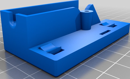
I used the smaller relay for this. The relay installs into the printed box and is held in place by some friction protrusions. You're going to put the relay into the opening at a tilt and then roll it down into these protrusions to keep the relay in place.
You need to strip off the power cable jacket to expose the wiring and you'll cut and install the black wire in to the relay NO(Normally Open/COM) inputs. Easiest way to do this is to cut the cable where you want to install your relay and then strip back 7cm on each end.
Cut off the excess white and green wire and solder those back together covered with heatshrink and maybe put two wraps of electric tape over one connection to ensure no pointed bits work their way through the headshrink. This should provide enough of the black/hot wire loop to pull over to the relay location to then cut and terminate the wires in the relay. I pull the loop in to place first to ensure I'm cutting the wire in a location that yields the longest leads to the termination.
Amazon has the GPIO jumpers. $2.50 or so from China if you can wait a few weeks: https://www.aliexpress.com/item/32349445870.html
The GPIO outputs only 3.3V so I used 3.3V to power the relay as well which works great.
Note when you connect to a GPIO and configure it in the plugin, the plugin references the 1-40 pin number, not the GPIO number.
This works great but I also wanted to toggle my LED power and enclosure exhaust fan so I built a new version that holds a 10mm cable and I toggle power to a small power strip for all three devices.
Ziptie openings are chamfered so just push the ziptie in and it should come out the other side.
Held closed with a M3x12 screw. This set is pretty handy for your projects (https://www.amazon.com/VIGRUE-M2-M3-M4-1080PCS-Stainless-Screws-Socket/dp/B071KBVZVV/).
I leave Octoprint running 24/7. When I want to print, I click connect which turns this relay on. 30 seconds later I'm ready to print. After my print completes, the plugin will turn off the relay after a set amount of time. I have mine set to 30 minutes. This has worked flawlessly for me.
USB Box
Image above shows how to wire this to turn on power to the power strip when the USB port has power. I use this on my son's PC to turn on his wall LED art. The LEDs were too much to run off a standard USB port so I did the next best thing and turn the power on and off based on just a USB port on the PC. When the PC is off, so is the power to the USB connection and the relay is open. When the PC is powered on, the USB port turns on the relay and since 'IN' is tied to ground, the relay closes and turns on power to the power strip.
Two relay type / size boxes are available here... regular and an optocoupler relay. The optocoupler better isolates the relay control from the rest of the board is how I've read it. I've not had any issues with the smaller regular relay with switching power on and off via USB so far.
Standard Relay - https://www.aliexpress.com/item/32708600505.html
Optocoupler Relay - https://www.aliexpress.com/item/32983499479.html
I've documented two different ways to switch with this relay below.
Ziptie insertion is easier if you bend the last 1cm or so of the zip tie end to make the curve as you insert it.
USB power control description below this one
I wanted to toggle power for my Prusa printer via OctoPrint using 3.3V/Ground/GPIO on the Pi via this plugin https://plugins.octoprint.org/plugins/psucontrol/.
I used the smaller relay for this. The relay installs into the printed box and is held in place by some friction protrusions. You're going to put the relay into the opening at a tilt and then roll it down into these protrusions to keep the relay in place.
You need to strip off the power cable jacket to expose the wiring and you'll cut and install the black wire in to the relay NO(Normally Open/COM) inputs. Easiest way to do this is to cut the cable where you want to install your relay and then strip back 7cm on each end.
Cut off the excess white and green wire and solder those back together covered with heatshrink and maybe put two wraps of electric tape over one connection to ensure no pointed bits work their way through the headshrink. This should provide enough of the black/hot wire loop to pull over to the relay location to then cut and terminate the wires in the relay. I pull the loop in to place first to ensure I'm cutting the wire in a location that yields the longest leads to the termination.
Amazon has the GPIO jumpers. $2.50 or so from China if you can wait a few weeks: https://www.aliexpress.com/item/32349445870.html
The GPIO outputs only 3.3V so I used 3.3V to power the relay as well which works great.
Note when you connect to a GPIO and configure it in the plugin, the plugin references the 1-40 pin number, not the GPIO number.
This works great but I also wanted to toggle my LED power and enclosure exhaust fan so I built a new version that holds a 10mm cable and I toggle power to a small power strip for all three devices.
Ziptie openings are chamfered so just push the ziptie in and it should come out the other side.
Held closed with a M3x12 screw. This set is pretty handy for your projects (https://www.amazon.com/VIGRUE-M2-M3-M4-1080PCS-Stainless-Screws-Socket/dp/B071KBVZVV/).
I leave Octoprint running 24/7. When I want to print, I click connect which turns this relay on. 30 seconds later I'm ready to print. After my print completes, the plugin will turn off the relay after a set amount of time. I have mine set to 30 minutes. This has worked flawlessly for me.
USB Box
Image above shows how to wire this to turn on power to the power strip when the USB port has power. I use this on my son's PC to turn on his wall LED art. The LEDs were too much to run off a standard USB port so I did the next best thing and turn the power on and off based on just a USB port on the PC. When the PC is off, so is the power to the USB connection and the relay is open. When the PC is powered on, the USB port turns on the relay and since 'IN' is tied to ground, the relay closes and turns on power to the power strip.