GrabCAD
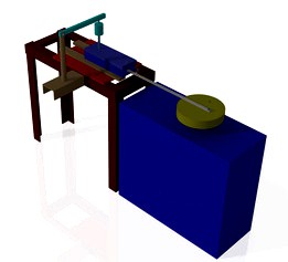
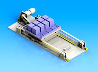
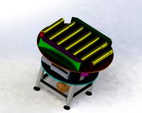
Reciprocating Mechanism for Rotary Wear Testing Machine
by GrabCAD
Last crawled date: 1 year, 11 months ago
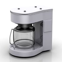
The Objective of the project is to investigate the pin on disc wear testing machine and to develop a suitable mechanism to convert the continuous rotary motion to reciprocating motion without hindering the original functionality.
Steps:
1. The Project involved studying the existing machine, developing a concept such that it doesn't hinder the original functionality.
2. It involved developing a suitable concept, Designing the components through Hand calculations, Developing CAD Model in CATIA, Drafting with the Bill of Materials.
3. Manufacturing the components with the laboratory equipment and testing with a standard materials.
The Calculations involved:
1. Calculating the torque on the motor side to prove that it can overcome the resisting torque.
2. Calculating the length and cross-section of connecting rod based on stroke length.
3. Calculating the height and loads on the structure.
4. Calculating the dimensions of the block and plate.
5. Selection of appropriate materials for the components.
6. Fabrication with operations like shearing, drilling, and Milling
Manufacturing Processes Involved:
1. Drilling - For drilling the various holes and tapping them.
2. Shearing - For cutting MS Angle to the appropriate length for the structure.
3. Welding - Structure and base plate on the structure.
4. Milling - For making the slot in Slider Block
5. Lathe - Turning
List of Components:
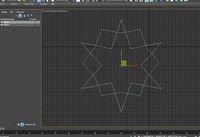
1. Circular Disc
2. Connecting Rod (12x6x480 mm)
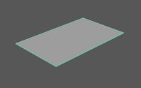
3. Flat Plate (250×100×10mm)
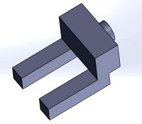
4. Slider Block
5. Slider
6. Flat Plate (350x250x1mm)
7. Structure made up of MS Angle (50x50x2mm)
8. C-Channel
9. Screw M4x16 and Screw M6x55
Steps:
1. The Project involved studying the existing machine, developing a concept such that it doesn't hinder the original functionality.
2. It involved developing a suitable concept, Designing the components through Hand calculations, Developing CAD Model in CATIA, Drafting with the Bill of Materials.
3. Manufacturing the components with the laboratory equipment and testing with a standard materials.
The Calculations involved:
1. Calculating the torque on the motor side to prove that it can overcome the resisting torque.
2. Calculating the length and cross-section of connecting rod based on stroke length.
3. Calculating the height and loads on the structure.
4. Calculating the dimensions of the block and plate.
5. Selection of appropriate materials for the components.
6. Fabrication with operations like shearing, drilling, and Milling
Manufacturing Processes Involved:
1. Drilling - For drilling the various holes and tapping them.
2. Shearing - For cutting MS Angle to the appropriate length for the structure.
3. Welding - Structure and base plate on the structure.
4. Milling - For making the slot in Slider Block
5. Lathe - Turning
List of Components:
1. Circular Disc
2. Connecting Rod (12x6x480 mm)
3. Flat Plate (250×100×10mm)
4. Slider Block
5. Slider
6. Flat Plate (350x250x1mm)
7. Structure made up of MS Angle (50x50x2mm)
8. C-Channel
9. Screw M4x16 and Screw M6x55
Similar models
cg_trader
$2

Slider Mechanism
...ion, as in a reciprocating piston engine, or to convert rotary motion to straight-line motion, as in a reciprocating piston pump.
grabcad
free

Slider Crank Mechanism (SCM)
...edly opening and closing drawers, tens of thousands of times. testing door handles by repeatedly lowering and lifting the handle.
grabcad
free

Slider Crank Mechanism
...ary motion, as in a reciprocating engine, or to convert rotary motion to straight line motion, as in a reciprocating piston pump.
grabcad
free

Slider Crank Mechanism
...ion, as in a reciprocating piston engine, or to convert rotary motion to straight-line motion, as in a reciprocating piston pump.
grabcad
free

slider crank mechanism
...ion, as in a reciprocating piston engine, or to convert rotary motion to straight-line motion, as in a reciprocating piston pump.
grabcad
free

Slider Crank
...slider crank
grabcad
slider crank is mainly used to convert rotary motion to a reciprocating motion or vice versa.
grabcad
free

slider crank mechanism
...aight-line motion, as in a reciprocating piston pump. ... on a reciprocating piston pump the crankshaft would be driven by a moto
grabcad
free

Slider Crank Mechanism
...ion, as in a reciprocating piston engine, or to convert rotary motion to straight-line motion, as in a reciprocating piston pump.
grabcad
free

Slider Crank Mechanism
...grabcad
slider crank mechanism involves conversion of reciprocating motion of piston into rotatry motion of shaft and viceversa.
grabcad
free

Slider Crank Mechanism
...tion, as in a reciprocating piston engine, or to convert rotary motion to straight-line motion, as in a reciprocating piston pump
Reciprocating
3d_export
$6

Reciprocating Motion
...#39;vinci's reciprocating motion contraption the model is used for picking up buckets of water from a well materials included
3d_export
$5

horizontal reciprocating mask packaging machine
... reciprocating mask packaging machine<br>3d drawing model of horizontal reciprocating mask packaging machine solidworks stp
3d_export
$14
reciprocating saw
...br textures. fbx obj pbr textures with 5 different colour variants packed grayscale textures, occlusion, roughness & metallic
3d_export
$15
horizontal reciprocating mask packaging machine
...r boxes, product cartons are placed on a row of crossbeam shelves by pallets, and can be accessed and accessed by any single tray
3d_export
$8

Cam and Follower
...follower rises and falls in a process known as reciprocating ...
3d_export
$95
Falcon 3D C182 Skylane F06 3D Model
...civilian civil commuter trainer personal family professional training monoplane reciprocating propeller opposed inline four place falcon 3d c182 skylane...
3d_export
$10

camshaft moped motorcycle motorbike
... the push rod, the valve is completely open. the valve is closed when the spring pulls it back and the cam is on its base circle.
3d_export
$5
traverse mechanism of heavy workpiece
...the conveyor.<br>in order to obtain the forward precision of reciprocating straight line.<br>key points of design<br>calculation process of main parts<br>verify...
thingiverse
free

Reciprocating Mechanism
...d in jig-saw typed power tools. could also be used to turn reciprocating energy back into rotational.https://youtu.be/vl-jwvzgpns
free3d
free

Reciprocating Saw v1
...reciprocating saw v1
free3d
reciprocating saw v1 printable, low poly model.
Rotary
3ddd
$1
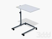
Medical Rotary table
...medical rotary table
3ddd
медицинский стол
medical rotary table
turbosquid
$18

Codex Rotary
...squid
royalty free 3d model codex rotary for download as stl on turbosquid: 3d models for games, architecture, videos. (1439894)
turbosquid
$12
Rotary drill
...y free 3d model rotary drill for download as ma, obj, and fbx on turbosquid: 3d models for games, architecture, videos. (1394316)
3d_export
$6

The rotary module 3D Model
...the rotary module 3d model
3dexport
the rotary module
the rotary module 3d model armata2015 98145 3dexport
turbosquid
$40
Rotary Engine
... available on turbo squid, the world's leading provider of digital 3d models for visualization, films, television, and games.
turbosquid
$15

Rotary Phone
... available on turbo squid, the world's leading provider of digital 3d models for visualization, films, television, and games.
turbosquid
$10

ROTARY medal
... available on turbo squid, the world's leading provider of digital 3d models for visualization, films, television, and games.
turbosquid
$9
Rotary conveyor
...veyor for download as 3ds, max, ige, obj, fbx, stl, and sldas on turbosquid: 3d models for games, architecture, videos. (1300472)
3d_export
$5
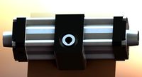
Rotary Cylinder 3D Model
...rotary cylinder 3d model
3dexport
rotary cylinder pneumatic pressure torque
rotary cylinder 3d model fau 71217 3dexport
3ddd
$1
Medical Rotary Table M2
...medical rotary table m2
3ddd
медицинский , стол
medical rotary table m2
Wear
turbosquid
free

soilder wear
...ar
turbosquid
free 3d model soilder wear for download as max on turbosquid: 3d models for games, architecture, videos. (1144149)
3d_export
$5
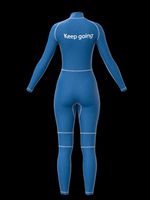
diving wear fbx
...diving wear fbx
3dexport
diving wear fbx made sofeware clo,marvelous designer
turbosquid
$60

Male In Casual Wear
... available on turbo squid, the world's leading provider of digital 3d models for visualization, films, television, and games.
turbosquid
$60

Arnold_ formal wear
... available on turbo squid, the world's leading provider of digital 3d models for visualization, films, television, and games.
3d_export
$18

women wear 01 3D Model
...women wear 01 3d model
3dexport
women wear shoes sandles beach vray
women wear 01 3d model prediator 6294 3dexport
turbosquid
$40

Boy wearing Mask and Gloves
... free 3d model boy wearing mask and gloves for download as ma on turbosquid: 3d models for games, architecture, videos. (1562410)
turbosquid
$5

Modern PBR Stove with Wear
...odern pbr stove with wear for download as obj, fbx, and blend on turbosquid: 3d models for games, architecture, videos. (1186746)
turbosquid
$39

Young Guy in Casual Wear
... available on turbo squid, the world's leading provider of digital 3d models for visualization, films, television, and games.
turbosquid
$10
Musket Pistol Gun With Wearing
... available on turbo squid, the world's leading provider of digital 3d models for visualization, films, television, and games.
turbosquid
$10

Realistic Mannequin - Ladies Western Wear
...d model ladies western wear for download as obj, fbx, and pac on turbosquid: 3d models for games, architecture, videos. (1462327)
Mechanism
3d_export
$50
Mechanism
...mechanism
3dexport
mechanism -------- animation is present only in the blender file.
3d_export
$5

mechanics
...mechanics
3dexport
turbosquid
$50

mechanic
... available on turbo squid, the world's leading provider of digital 3d models for visualization, films, television, and games.
3ddd
$1

Mechanical Wasp
...mechanical wasp
3ddd
робот
mechanical wasp
3d_export
$20
Mechanical tail
...mechanical tail
3dexport
mechanical tail<br>four-part movement
3d_export
$5

mechanical ballista
...mechanical ballista
3dexport
a mechanical ballista useful for medieval or fantasy games does not contain animations
turbosquid
$59

Mechanical Part
...id
royalty free 3d model mechanical part for download as c4d on turbosquid: 3d models for games, architecture, videos. (1410833)
turbosquid
$50

Mechanical Spider
...royalty free 3d model mechanical spider for download as blend on turbosquid: 3d models for games, architecture, videos. (1599864)
turbosquid
$45

Mechanical Pencil
...royalty free 3d model mechanical pencil for download as blend on turbosquid: 3d models for games, architecture, videos. (1503379)
turbosquid
$35

Mechanical fish
...id
royalty free 3d model mechanical fish for download as max on turbosquid: 3d models for games, architecture, videos. (1152530)
Machine
archibase_planet
free
Machine
...machine
archibase planet
sewing-machine sewing machine equipment
singer machine- 3d model for interior 3d visualization.
archibase_planet
free

Machine
...hine
archibase planet
percolator equipment coffee-machine
machine n230708 - 3d model (*.gsm+*.3ds) for interior 3d visualization.
archibase_planet
free
Machine
...chibase planet
percolator coffee-machine kitchen equipment
coffee machine - 3d model (*.gsm+*.3ds) for interior 3d visualization.
archibase_planet
free

Slot machine
...ase planet
slot machine slot-machine playing machine
slot machine n260311 - 3d model (*.gsm+*.3ds) for interior 3d visualization.
turbosquid
$7

Machine
...ne
turbosquid
royalty free 3d model machine for download as on turbosquid: 3d models for games, architecture, videos. (1391792)
3d_ocean
$10
War machine
...war machine
3docean
camuflage machine robot war war machine
war machine created in 3dmax 2009 15.497-poly count
turbosquid
$7
machine
...turbosquid
royalty free 3d model machine for download as obj on turbosquid: 3d models for games, architecture, videos. (1452674)
3d_ocean
$12
Weighing-machine
...weighing-machine
3docean
market shop weighing-machine
3d model weighing-machine
archibase_planet
free

Sewing machine
...ine
archibase planet
sewing machine sewing-machine
sewing machine n080311 - 3d model (*.gsm+*.3ds) for interior 3d visualization.
archibase_planet
free
Coffee machine
...se planet
coffee machine percolator coffee-machine
coffee machine n010715 - 3d model (*.gsm+*.3ds) for interior 3d visualization.
Testing
turbosquid
$99

test
...st
turbosquid
royalty free 3d model test for download as max on turbosquid: 3d models for games, architecture, videos. (1251637)
turbosquid
$63
TEST
...st
turbosquid
royalty free 3d model test for download as max on turbosquid: 3d models for games, architecture, videos. (1446233)
turbosquid
$1
test
...st
turbosquid
royalty free 3d model test for download as fbx on turbosquid: 3d models for games, architecture, videos. (1360941)
3d_export
free

johnny test
...johnny test
3dexport
johnny test 3d
turbosquid
$15

Test
... available on turbo squid, the world's leading provider of digital 3d models for visualization, films, television, and games.
turbosquid
$2

test
... available on turbo squid, the world's leading provider of digital 3d models for visualization, films, television, and games.
turbosquid
free

Test
... available on turbo squid, the world's leading provider of digital 3d models for visualization, films, television, and games.
turbosquid
free

test
... available on turbo squid, the world's leading provider of digital 3d models for visualization, films, television, and games.
turbosquid
free

Test
... available on turbo squid, the world's leading provider of digital 3d models for visualization, films, television, and games.
3d_export
$5
gripper test
...gripper test
3dexport
robot gripper test model