Thingiverse
Raspberry Pi mount for Ender 5 electronics enclosure
by Thingiverse
Last crawled date: 4 years, 3 months ago
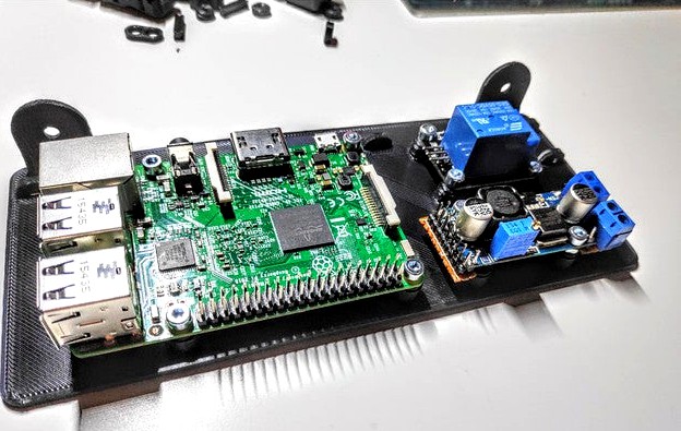
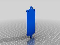
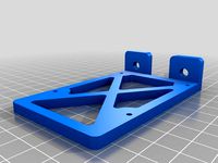
ENDER 5 electronics mounting plate for Raspberry Pi
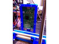
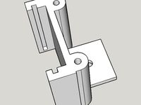
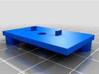
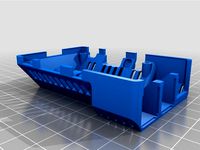
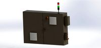
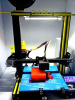
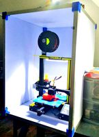
This mounting plate is designed to be placed inside the electronics case of an Creality Ender 5.
It should hook under the power switch on the left side of the case and has holes to be screwed onto the side of the Landy-PSU using M4 Screws.
It's main use is holding a Raspberry Pi with Octoprint.
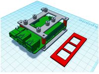
It can hold a LM2596 Board like this. I extended it with multiple terminal blocks and 2.54mm pins for easier cable management.
The LM2596 is set to output 5.1V with an input of 24V. This can power the Raspberry Pi by connecting to the 5V and GND pins on the Pi.
It can also hold a SRD-05VDC-SL-C Relay board to be used with Octoprint PSU Control. You can deliver 5V to it directly from the LM2596 and control it with any BCM-Pin from the Raspberry Pi. I used BCM-17.
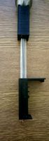
I had this laying around and don't remember where I got the board from. The mounting holes are 21mm and 28mm away from each other. You can easily tweak the distances in the FreeCAD File I included.
Everything can be screwed in using M3 Screws, besides the PSU mount, which needs M4.
The screws will cut their own threads into the plastic. I tested this using 8mm M3 Screws which hold everything perfectly.
There are loops for cable ties to allow a clean cable management. If you don't like them, don't use them.
Known Problems:
This is my first 3D modelling project. Criticism and help welcome.
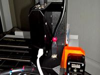
Initially I modelled the PSU-connecting M4-holes 1 mm to close to each other. I fixed this in the model, but haven't printed and tested the new version yet. I simply used some double sided tape to stick the mounting plate into the electronics container. This is why you don't see the M4 screws in my photos.
If you print and try this, I would really appreciate some pictures and feedback if everything fits.
I realised the Raspberry Pi doesn't use M3 but something like M2.5 Screws. Because I had planned to use M3 screws and wanted to use the same screws for all parts, I simply forced them into the Raspberry Pi PCB. The screws easily cut their thread in the PCB and after a few extra rotations everything fitted easily. You could also use a 3mm drill bit to widen the hole carefully. Feel free to remix my FreeCAD file to hold M2.5 Screws instead.
My Raspberry Pi has no cooling at all and there are no holes in the case to allow airflow over the Pi. I'm thinking about mounting the Pi further to the left so that the CPU is over the holes further to the left. But this would mess up my cable management. I'm also thinking about drilling some extra holes and mounting a fan to the lid like the fan further right, that is cooling the Printer control board.
For now, I didn't have a problem with thermals yet, but I will add at least a heatsink soon.
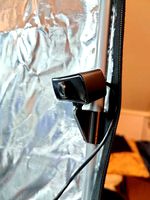
My rather old Raspberry Pi 3B had a broken Wifi chip since I bought it. I added a USB extension cord to it and mounted a cheap RT2571 stick at the outside of the printer.
I assume that the build-in Wifi of the Pi will significantly decrease when it is isolated by the metal box. I recommend feeding an extension cord to the outside and sticking something cheap like MT7601, RT3572, RT3070 or AR9271 to the frame of your printer. All of them should work out of the box.
Of cause you can always wire a LAN-Cable through the cable hole and connect your Raspberry Pi through that.
I wanted to connect the Raspberry Pi to the printer board using just 3 wires and get a serial connection through that so that I don't have to the USB port on the outside. It didn't work for me. Maybe I need some other Marlin configuration or the SPI port on the Creality 1.1.5 Port just isn't made for that. Maybe I will upgrade to a SKR E3, SKR v1.4 or something else.
If you know something I could do, please let me know.
For now, I simply wired a mini-USB-Cable out through the LCD connector hole and connected it externally to the Printer board.
This mounting plate is designed to be placed inside the electronics case of an Creality Ender 5.
It should hook under the power switch on the left side of the case and has holes to be screwed onto the side of the Landy-PSU using M4 Screws.
It's main use is holding a Raspberry Pi with Octoprint.
It can hold a LM2596 Board like this. I extended it with multiple terminal blocks and 2.54mm pins for easier cable management.
The LM2596 is set to output 5.1V with an input of 24V. This can power the Raspberry Pi by connecting to the 5V and GND pins on the Pi.
It can also hold a SRD-05VDC-SL-C Relay board to be used with Octoprint PSU Control. You can deliver 5V to it directly from the LM2596 and control it with any BCM-Pin from the Raspberry Pi. I used BCM-17.
I had this laying around and don't remember where I got the board from. The mounting holes are 21mm and 28mm away from each other. You can easily tweak the distances in the FreeCAD File I included.
Everything can be screwed in using M3 Screws, besides the PSU mount, which needs M4.
The screws will cut their own threads into the plastic. I tested this using 8mm M3 Screws which hold everything perfectly.
There are loops for cable ties to allow a clean cable management. If you don't like them, don't use them.
Known Problems:
This is my first 3D modelling project. Criticism and help welcome.
Initially I modelled the PSU-connecting M4-holes 1 mm to close to each other. I fixed this in the model, but haven't printed and tested the new version yet. I simply used some double sided tape to stick the mounting plate into the electronics container. This is why you don't see the M4 screws in my photos.
If you print and try this, I would really appreciate some pictures and feedback if everything fits.
I realised the Raspberry Pi doesn't use M3 but something like M2.5 Screws. Because I had planned to use M3 screws and wanted to use the same screws for all parts, I simply forced them into the Raspberry Pi PCB. The screws easily cut their thread in the PCB and after a few extra rotations everything fitted easily. You could also use a 3mm drill bit to widen the hole carefully. Feel free to remix my FreeCAD file to hold M2.5 Screws instead.
My Raspberry Pi has no cooling at all and there are no holes in the case to allow airflow over the Pi. I'm thinking about mounting the Pi further to the left so that the CPU is over the holes further to the left. But this would mess up my cable management. I'm also thinking about drilling some extra holes and mounting a fan to the lid like the fan further right, that is cooling the Printer control board.
For now, I didn't have a problem with thermals yet, but I will add at least a heatsink soon.
My rather old Raspberry Pi 3B had a broken Wifi chip since I bought it. I added a USB extension cord to it and mounted a cheap RT2571 stick at the outside of the printer.
I assume that the build-in Wifi of the Pi will significantly decrease when it is isolated by the metal box. I recommend feeding an extension cord to the outside and sticking something cheap like MT7601, RT3572, RT3070 or AR9271 to the frame of your printer. All of them should work out of the box.
Of cause you can always wire a LAN-Cable through the cable hole and connect your Raspberry Pi through that.
I wanted to connect the Raspberry Pi to the printer board using just 3 wires and get a serial connection through that so that I don't have to the USB port on the outside. It didn't work for me. Maybe I need some other Marlin configuration or the SPI port on the Creality 1.1.5 Port just isn't made for that. Maybe I will upgrade to a SKR E3, SKR v1.4 or something else.
If you know something I could do, please let me know.
For now, I simply wired a mini-USB-Cable out through the LCD connector hole and connected it externally to the Printer board.
Similar models
thingiverse
free
Raspberry Pi Zero Mounting Plate by liamnettleton
...r using m4 t-nuts.
use m2.5 screws to mount the board itself to the mount.
feel free to remix or change this as you like. thanks!
thingiverse
free
Raspberry Pi 3 Mount for 2020 Extrusion by minko
...ead of m2. i tapped the holes in the mount for m3 (so don't need nuts) and drilled the mounting holes in raspberry pi to 3mm.
thingiverse
free

Ramps 1.4 Box Enclosure Case TL Smoother Raspberry Pi Holder Fan Wanhao i3 by BastelOle
...p you can mount any 80mm fan. you only need some m3 and m4 screws for mounting the boards. for the raspberry i used some spacers.
thingiverse
free
Raspberry Pi 2020 holder by Euter
...ews with spacers to mount raspberry pi. you can mount raspberry pi to both sides. m3 holes are designed to be tapped with m3 tap.
thingiverse
free

SFX PSU Holder for AM8 2040 Extrusion 3D Printer/Laser/CNC by KadenShayden
...ferent mounting holes. i am using a silverstone 450w bronze psu v3.0.
you will need m3 screws in order to mount this psu to this.
thingiverse
free
Raspberry Pi camera board holder by maglub
...nting holes to mount the holder on, for example, a paper clip, as well as a screw hole to fit it on something else using a screw.
thingiverse
free

Pi Plate - surface mount for Raspberry Pi by reactron
...4 wood screws. works fine. i'll probably use ca glue to mount the assembly, but there are 3mm holes for mounting with screws.
thingiverse
free
CR-10 Raspberry Pi Integration by michaeldeberry
...haust fan to mount everything as they were the perfect length. to mount the new fan i used some m3x12mm screws that i had around.
thingiverse
free
S8 RPI/LM2596 internal mount by Sparkss
...ew firmware, for example.
as always i have included the openscad files for anyone that wants to modify to better fit their needs.
thingiverse
free
Original Prusa MK2 style Octopi cover by luc_e
...pi on the top using the 2 x m3 countersunk 16mm screws.
connect you wifi adapter, power and usb cable and you're done.
enjoy!
Raspberry
3d_export
free

raspberry
...raspberry
3dexport
3d model of a raspberry. i tried to make it realistic.
turbosquid
$27
Raspberries
...y free 3d model raspberries for download as max, obj, and stl on turbosquid: 3d models for games, architecture, videos. (1354176)
turbosquid
$14

Raspberries
...y free 3d model raspberries for download as max, obj, and fbx on turbosquid: 3d models for games, architecture, videos. (1364663)
3d_export
$5
raspberry pi
...raspberry pi
3dexport
carcasa para la raspberry pi
turbosquid
$99

Raspberry
... available on turbo squid, the world's leading provider of digital 3d models for visualization, films, television, and games.
turbosquid
$10

raspberries
... available on turbo squid, the world's leading provider of digital 3d models for visualization, films, television, and games.
archive3d
free

Raspberries 3D Model
...raspberries 3d model archive3d raspberries raspberry raspberries n300911 - 3d model (*.3ds) for interior 3d...
3d_export
$5

raspberry fruit
...raspberry fruit
3dexport
3d_export
$5

raspberry
...y different sizes. their color ranges from light burgundy to pink. there are formats: obj, 3ds, blend, dae, fbx, mtl.<br>:)
evermotion
$12

raspberries 23 am130
...evermotion raspberries 23 am130 evermotion key 23 food fruit raspberry fruits am130 raspberries highly detailed 3d model of raspberries...
Enclosure
3d_export
free
electrical enclosure
...l enclosure where electrical devices like (relays, contactors, busbars ) are kept in order to protect from hazardous environment.
turbosquid
$100

GPU Enclosure
...yalty free 3d model gpu enclosure for download as obj and stl on turbosquid: 3d models for games, architecture, videos. (1381061)
3d_export
$5
Electrical Enclosure
...ed. also has tower lights attaced on the top.<br>file format that are available:<br>.step<br>.obj<br>.stl
archive3d
free
Enclosure 3D Model
...closure 3d model
archive3d
shower enclosure-acquarius- 3d model for interior 3d visualization.
archive3d
free
Enclosure 3D Model
...enclosure 3d model
archive3d
shower enclosure-omega- 3d model for interior 3d visualization.
archive3d
free
Enclosure 3D Model
...enclosure 3d model
archive3d
shower enclosure-vega - 3d model for interior 3d visualization.
archive3d
free
Enclosure 3D Model
...enclosure 3d model
archive3d
shower enclosure-zenith - 3d model for interior 3d visualization.
turbosquid
$20
shower enclosure
... available on turbo squid, the world's leading provider of digital 3d models for visualization, films, television, and games.
turbosquid
$14
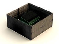
Dumpster Enclosure
... available on turbo squid, the world's leading provider of digital 3d models for visualization, films, television, and games.
turbosquid
$25
3d printer enclosure
... model 3d printer enclosure for download as ipt, skp, and fbx on turbosquid: 3d models for games, architecture, videos. (1634310)
Ender
3ddd
$1
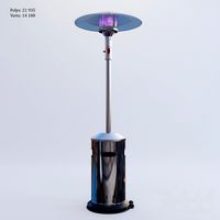
Enders / Elegance
...enders / elegance
3ddd
обогреватель
уличный газовый обогреватель enders elegance
высота: 2200 мм
3d_export
free
ender 3 frame cavity covers
... of the creality ender 3 - makes it look a bit more attractive it just slides into the open channels of the aluminium framework
turbosquid
$1
pen support for ender 3
...y free 3d model pen support for ender 3 for download as blend on turbosquid: 3d models for games, architecture, videos. (1611282)
3d_ocean
$9
Ender Dragon Minecraft
...ojang obj poly videogames
ender dragon minecraft created with cinema 4d r15 formats included: max 2013 – fbx 2012 – c4d r15 – obj
3d_export
free
Creality ender enclosure webcam mount
...e creality enclosure. sure is better than a tripod. change it up if it helps. i printed pla with 50% infill on my dd ender 3 pro.
3d_export
free
ender 3 enclosure corners
...er corners and 4 upper corners, using 25mmx25mm angled aluminium pieces that gets covered on inside of the frame with plexiglass
3d_export
free
ender 3 3d print bed clips
...ed + normal aluminium bed frame of the creality ender 3 = 6mm (b) these clips are designed for glass plate + aluminium bed = 4mm
3d_export
$5
GRUMPY CAT
...grumpy cat 3dexport grumpy cat to print in ender ...
3d_export
$5

Logs fire
...with one multi material for corona and vray r ender. albedo, normal, uvmap, roughness format jpg 4096x4096 models:...
3d_export
$42

excavator
...is the original size. 0.12 mm printing surface creality ender5 ...
Pi
design_connected
$11

Pi
...pi
designconnected
ligne roset pi chairs computer generated 3d model. designed by thibault desombre.
3d_export
$5
raspberry pi
...raspberry pi
3dexport
carcasa para la raspberry pi
turbosquid
$18
pied
... available on turbo squid, the world's leading provider of digital 3d models for visualization, films, television, and games.
3ddd
$1
Emme pi light
...emme pi light
3ddd
emme pi light
люста emme pi light
3ddd
$1
Emme pi light
...emme pi light
3ddd
emme pi light
бра классическое emme pi light
3ddd
$1

Emme Pi Light
...emme pi light
3ddd
emme pi light
3ddd
$1

Emme Pi Light
...emme pi light
3ddd
emme pi light
design_connected
$16
Pi-Air
...pi-air
designconnected
living divani pi-air lounge chairs computer generated 3d model. designed by harry & camila.
3d_ocean
$15

Manneken Pis
...picting a naked little boy urinating into a fountain’s basin. (wikipedia) the model was sculpted in blender 2.70a rendered wit...
3ddd
$1
Emme pi light
...emme pi light
3ddd
emme pi light
люстра классическая фирма: emme pi light
артикул: 3595/5/cot/12/wh
Electronics
turbosquid
$1

electron
...urbosquid
royalty free 3d model electron for download as max on turbosquid: 3d models for games, architecture, videos. (1157488)
turbosquid
$50

electronic
...
royalty free 3d model electronic for download as max and obj on turbosquid: 3d models for games, architecture, videos. (1289427)
turbosquid
$40

Electron
... available on turbo squid, the world's leading provider of digital 3d models for visualization, films, television, and games.
3d_ocean
$8

Electronic game
...electronic game
3docean
electronic games nu pogody wait a minute well
electronic game “well, wait a minute”, “nu pogody”
3ddd
$1
Brilux Electronic
...brilux electronic
3ddd
подвес. brilux electronic. польша. материалы настроены.
3d_export
free

electronic shop
...lectronic shop with high quality interior and exterior. it has tvs smartphone play station printer and many more electronic item.
3ddd
$1

Термостаты OJ Electronics
...ермостаты oj electronics
3ddd
oj electronics , термостат
термостаты фирмы oj electronics
3d_export
$8

electron 714
...electron 714
3dexport
game ready model for export to unreal engine soviet tv electron 714 pbr 4k
3ddd
$1

Термостат OJ Electronics
... oj electronics
3ddd
oj electronics , термостат
термостат occ2-1991 фирмы oj electronics
turbosquid
$60
Electronics Stuff
...
royalty free 3d model electronics stuff for download as max on turbosquid: 3d models for games, architecture, videos. (1624680)
Mount
3d_export
free

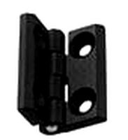
mounting bracket
...mounting plate is the portion of a hinge that attaches to the wood. mounting plates can be used indoors, cabinetry and furniture.
turbosquid
$2

MOUNTING
... available on turbo squid, the world's leading provider of digital 3d models for visualization, films, television, and games.
turbosquid
free

Mounts
... available on turbo squid, the world's leading provider of digital 3d models for visualization, films, television, and games.
turbosquid
free

Mount Fuji
...fuji
turbosquid
free 3d model mount fuji for download as obj on turbosquid: 3d models for games, architecture, videos. (1579977)
3d_export
$5

Headphone mount LR
...headphone mount lr
3dexport
headphone mount l+r
turbosquid
$39

Mount rainier
...quid
royalty free 3d model mount rainier for download as fbx on turbosquid: 3d models for games, architecture, videos. (1492586)
turbosquid
$5

pipe mounting
...quid
royalty free 3d model pipe mounting for download as obj on turbosquid: 3d models for games, architecture, videos. (1293744)
turbosquid
$3

Mounting Tires
...uid
royalty free 3d model mounting tires for download as fbx on turbosquid: 3d models for games, architecture, videos. (1708511)
3d_export
$5

Magnetic GoPro Mount
...pro mount
3dexport
cool magnetic mount for gopro. allows you to mount the camera on flat metal surfaces and get exclusive shots.
turbosquid
$5

Stone Mount
...ty free 3d model stone mount for download as ma, obj, and fbx on turbosquid: 3d models for games, architecture, videos. (1370306)
5
turbosquid
$6

Rock 5-5
...urbosquid
royalty free 3d model rock 5-5 for download as obj on turbosquid: 3d models for games, architecture, videos. (1639063)
3d_export
$5
hinge 5
...hinge 5
3dexport
hinge 5
turbosquid
$10

A-5
... available on turbo squid, the world's leading provider of digital 3d models for visualization, films, television, and games.
turbosquid
$2
A-5
... available on turbo squid, the world's leading provider of digital 3d models for visualization, films, television, and games.
turbosquid
$12

Calligraphic Digit 5 Number 5
...hic digit 5 number 5 for download as max, obj, fbx, and blend on turbosquid: 3d models for games, architecture, videos. (1389333)
3ddd
$1

5 роз
...5 роз
3ddd
5 роз в стеклянной вазе
design_connected
$11

iPhone 5
...iphone 5
designconnected
apple iphone 5 computer generated 3d model.
3ddd
$1
Lola 5
...lola 5
3ddd
miniforms
lola 5 miniforms 300*65*134
3ddd
$1

Nexus 5
...dd
nexus , phone , телефон
google nexus 5 phone
3d_ocean
$15

iPhone 5
...iphone 5
3docean
3d 4d apple cinema iphone model modeling phone screen texture
iphone 5 3d model and texture realistic iphone 5.