Thingiverse
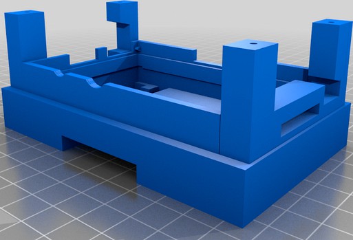
Raspberry Pi 1B DIN Mount controller by amyren
by Thingiverse
Last crawled date: 3 years, 3 months ago
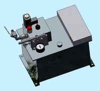
I made this because I needed to replace a faulty PLC controller og wanted to build my own.
My old Raspberry Pi model 1B was not being used anymore, so I figured it would be suitable for this task.
I purchased the output board from Bangood, a cheap 8 channel solid state relay board that can control 230VAC/2A and only need 3.3V DC to trigger.
The input board is self made, from an empty soldering board, 8 low voltage LED's, 300Ohm resistors and some terminals.
Everything is connected to the GPIO header on the Pi, and the IO's are also powered from the GPIO.
The control application is made with the Hollywood programming language, which use a few python scripts to communicate with the GPIO's.
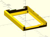
As might see from the pictures, all parts are printed in same colour, exept for the DIN-lock. This is because that part was reused from som other scrapped equipment. I did still make a STL file for it, to make this complete.
Also that metal spring for the lock is obviously not 3D printed. Here you will need to find a thin, suitable piece of metal.
I have just finished this print myself, and might add a lid for it later, just for the looks.
Relay board:https://www.banggood.com/no/8-Channel-5V-Solid-State-Relay-Low-Level-Trigger-DC-AC-PCB-SSR-In-5VDC-Out-240V-AC-2A-p-1558902.html
For the input board I used a prototype PCB, similar to this item:https://www.ebay.com/itm/5PCS-5x10cm-DIY-Multi-Hole-Prototype-Paper-PCB-Universal-Matrix-Circuit-Board-WM/163356760021
Ribbon cable 26 pin:https://www.ebay.com/itm/Flat-Ribbon-Cable-wires-26-pin-2-54mm-picth-200mm-Raspberry-Pi-GPIO-Header/172334334671
For 40 pin headers:https://www.ebay.com/itm/16CM-40-PIN-IDE-ATA-MOTHERBOARD-TO-DRIVE-RIBBON-CABLE-DATA-TRANSFER-UK-SELLER/362618699533
You can split the ribbeon cable and connect it directly to the I/O-boards, but I actually did use a male header to connect to my ribbon cable. similar to this:https://www.ebay.com/itm/Right-Angle-Pin-PCB-Box-Male-Header-2-0mm-IDC-JTAG-Socket-DC3-6-8-10-14-16P-50P/123804534693
Then I soldered the green, blue, red, orange and black wires to that header. This way I could use a longer ribbon cable in the testing phase of the I/O board. Later I changed to a shorter cable.
If I didnt have a spare old Raspberry pi 1b, I would probably go for the Raspberry Pi Zero. Order model W or WH if you want onboard WiFi. The WH model comes with the GPIO header pre-soldered.
I have included a wiring diagram. This is for RPi model 1B, which have a 26 pin GPIO header. Newer models have 40 pin GPIO headers with different pin numbers for the GPIO's.
My old Raspberry Pi model 1B was not being used anymore, so I figured it would be suitable for this task.
I purchased the output board from Bangood, a cheap 8 channel solid state relay board that can control 230VAC/2A and only need 3.3V DC to trigger.
The input board is self made, from an empty soldering board, 8 low voltage LED's, 300Ohm resistors and some terminals.
Everything is connected to the GPIO header on the Pi, and the IO's are also powered from the GPIO.
The control application is made with the Hollywood programming language, which use a few python scripts to communicate with the GPIO's.
As might see from the pictures, all parts are printed in same colour, exept for the DIN-lock. This is because that part was reused from som other scrapped equipment. I did still make a STL file for it, to make this complete.
Also that metal spring for the lock is obviously not 3D printed. Here you will need to find a thin, suitable piece of metal.
I have just finished this print myself, and might add a lid for it later, just for the looks.
Relay board:https://www.banggood.com/no/8-Channel-5V-Solid-State-Relay-Low-Level-Trigger-DC-AC-PCB-SSR-In-5VDC-Out-240V-AC-2A-p-1558902.html
For the input board I used a prototype PCB, similar to this item:https://www.ebay.com/itm/5PCS-5x10cm-DIY-Multi-Hole-Prototype-Paper-PCB-Universal-Matrix-Circuit-Board-WM/163356760021
Ribbon cable 26 pin:https://www.ebay.com/itm/Flat-Ribbon-Cable-wires-26-pin-2-54mm-picth-200mm-Raspberry-Pi-GPIO-Header/172334334671
For 40 pin headers:https://www.ebay.com/itm/16CM-40-PIN-IDE-ATA-MOTHERBOARD-TO-DRIVE-RIBBON-CABLE-DATA-TRANSFER-UK-SELLER/362618699533
You can split the ribbeon cable and connect it directly to the I/O-boards, but I actually did use a male header to connect to my ribbon cable. similar to this:https://www.ebay.com/itm/Right-Angle-Pin-PCB-Box-Male-Header-2-0mm-IDC-JTAG-Socket-DC3-6-8-10-14-16P-50P/123804534693
Then I soldered the green, blue, red, orange and black wires to that header. This way I could use a longer ribbon cable in the testing phase of the I/O board. Later I changed to a shorter cable.
If I didnt have a spare old Raspberry pi 1b, I would probably go for the Raspberry Pi Zero. Order model W or WH if you want onboard WiFi. The WH model comes with the GPIO header pre-soldered.
I have included a wiring diagram. This is for RPi model 1B, which have a 26 pin GPIO header. Newer models have 40 pin GPIO headers with different pin numbers for the GPIO's.
Similar models
cg_trader
$6

Raspberry Pi Neutral Mini-Hat Seat | 3D
... on top of the hat securing the hat in place. this unit is best used for storage of any hat not connected to a gpio ribbon cable.
grabcad
free

Raspberry Pi GPIO Breakout board
...raspberry pi gpio breakout board
grabcad
raspberry pi gpio breakout board with pin header 2x20 pin male, 8.4 mm high
cg_trader
$6

Raspberry Pi Hat Seat | 3D
...ock into the hat or rest on top of the hat securing the hat in place. this hat seat is designed for use with a gpio ribbon cable.
grabcad
free

40 pin connection header
...40 pin connection header
grabcad
40 pin connection header fits raspberry pi
thingiverse
free
Remix for GPIO ribbon cable opening - Raspberry Pi OctoPi Rig with 3.5" Adafruit Display
....5" display pcb, and an extension cable can be attached.
github repo remix_thing_2160917_octopi_rig_top_ribbon_cable_opening
cg_trader
$6

Raspberry Pi Mini HAT Seat | 3D
...is hat seat is designed for use with a gpio ribbon cable. this version is designed for smaller hats like the waveshare audio hat.
thingiverse
free

Raspberry Pi 7 inch Laptop by Slowmo5o
...enter.com/product/460968/3-model-bhttps://amzn.to/2qu1qvc
screws:https://amzn.to/2xjntpt
threaded inserts:https://amzn.to/2ofgy6d
grabcad
free

Raspberry Pi right angle case for GPIO headers
... headers
grabcad
allows the parallel connection of pins to the gpio header by fitting a second strip of headers inside the case.
thingiverse
free
26 Pin Cable Connector Cap by SCaruthers
....adafruit.com/products/1112) used on a guzunty expansion board (https://github.com/guzunty/pi/wiki) to prevent accidental shorts.
thingiverse
free

Raspberry Pi header cable pass-through (not compatible with A+ or B+) by critter42
...y pi header cable pass-through - for the 26-pin header cable of the a and b - this will not fit the 40pin cable of the a+ and b+!
1B
turbosquid
$76

1b
... available on turbo squid, the world's leading provider of digital 3d models for visualization, films, television, and games.
3d_export
$17

MQ-1B Predator
...mq-1b predator
3dexport
mq-1b predator
3ddd
$1
Italux MD9226-1B
...1b
3ddd
italux , italux md9226-1b
подвесной светильник italux md9226-1b
ф-20.0 h-150.0
turbosquid
$19

DSTV-1b
... available on turbo squid, the world's leading provider of digital 3d models for visualization, films, television, and games.
3ddd
$1
Cilento_MD93704-1B
...dd
cliento , illuminati
www.illuminati-lighting.comhttp://illuminati-light.com
3ddd
$1
PLISSE_PL 1B
...plisse_pl 1b
3ddd
дверь
дверь из коллекции plisse итальянской фабрики romagnoli
turbosquid
$15

Furniture hall 1b
... 3d model furniture hall 1b for download as max, obj, and fbx on turbosquid: 3d models for games, architecture, videos. (1142106)
turbosquid
$55

MAA-1B Piranha
...d model maa-1b piranha for download as 3ds, max, obj, and dae on turbosquid: 3d models for games, architecture, videos. (1334266)
turbosquid
$100

Supermarine Seafire 1B
... available on turbo squid, the world's leading provider of digital 3d models for visualization, films, television, and games.
turbosquid
$25

Street light 1b
... available on turbo squid, the world's leading provider of digital 3d models for visualization, films, television, and games.
Raspberry
3d_export
free

raspberry
...raspberry
3dexport
3d model of a raspberry. i tried to make it realistic.
turbosquid
$27
Raspberries
...y free 3d model raspberries for download as max, obj, and stl on turbosquid: 3d models for games, architecture, videos. (1354176)
turbosquid
$14

Raspberries
...y free 3d model raspberries for download as max, obj, and fbx on turbosquid: 3d models for games, architecture, videos. (1364663)
3d_export
$5

raspberry pi
...raspberry pi
3dexport
carcasa para la raspberry pi
turbosquid
$99

Raspberry
... available on turbo squid, the world's leading provider of digital 3d models for visualization, films, television, and games.
turbosquid
$10

raspberries
... available on turbo squid, the world's leading provider of digital 3d models for visualization, films, television, and games.
archive3d
free

Raspberries 3D Model
...raspberries 3d model archive3d raspberries raspberry raspberries n300911 - 3d model (*.3ds) for interior 3d...
3d_export
$5

raspberry fruit
...raspberry fruit
3dexport
3d_export
$5

raspberry
...y different sizes. their color ranges from light burgundy to pink. there are formats: obj, 3ds, blend, dae, fbx, mtl.<br>:)
evermotion
$12

raspberries 23 am130
...evermotion raspberries 23 am130 evermotion key 23 food fruit raspberry fruits am130 raspberries highly detailed 3d model of raspberries...
Pi
design_connected
$11
Pi
...pi
designconnected
ligne roset pi chairs computer generated 3d model. designed by thibault desombre.
3d_export
$5
raspberry pi
...raspberry pi
3dexport
carcasa para la raspberry pi
turbosquid
$18
pied
... available on turbo squid, the world's leading provider of digital 3d models for visualization, films, television, and games.
3ddd
$1

Emme pi light
...emme pi light
3ddd
emme pi light
люста emme pi light
3ddd
$1
Emme pi light
...emme pi light
3ddd
emme pi light
бра классическое emme pi light
3ddd
$1

Emme Pi Light
...emme pi light
3ddd
emme pi light
3ddd
$1

Emme Pi Light
...emme pi light
3ddd
emme pi light
design_connected
$16
Pi-Air
...pi-air
designconnected
living divani pi-air lounge chairs computer generated 3d model. designed by harry & camila.
3d_ocean
$15

Manneken Pis
...picting a naked little boy urinating into a fountain’s basin. (wikipedia) the model was sculpted in blender 2.70a rendered wit...
3ddd
$1
Emme pi light
...emme pi light
3ddd
emme pi light
люстра классическая фирма: emme pi light
артикул: 3595/5/cot/12/wh
Din
3d_export
$5
dinning table
...dinning table
3dexport
dinning table
turbosquid
$65

dinning
... available on turbo squid, the world's leading provider of digital 3d models for visualization, films, television, and games.
turbosquid
$25

dinning
... available on turbo squid, the world's leading provider of digital 3d models for visualization, films, television, and games.
turbosquid
$5

dinning
... available on turbo squid, the world's leading provider of digital 3d models for visualization, films, television, and games.
turbosquid
$0
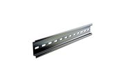
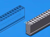
Din-rail
...n-rail
turbosquid
free 3d model din-rail for download as max on turbosquid: 3d models for games, architecture, videos. (1493979)
3d_export
$6

dinning room
...dinning room
3dexport
hi!
turbosquid
$25

Dinning table
...id
royalty free 3d model dinning table for download as blend on turbosquid: 3d models for games, architecture, videos. (1507735)
turbosquid
$10

Dinning Room
...osquid
royalty free 3d model dinning room for download as ma on turbosquid: 3d models for games, architecture, videos. (1369734)
turbosquid
$7

Dinning set
...osquid
royalty free 3d model dinning set for download as max on turbosquid: 3d models for games, architecture, videos. (1464995)
turbosquid
$5

Dinning room
...squid
royalty free 3d model dinning room for download as obj on turbosquid: 3d models for games, architecture, videos. (1601156)
Controller
3d_ocean
$4
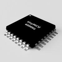
Controller TQFP32
...qfp32
3docean
chip controller cpu electronic gpu mcu micro controller silicon smd tqfp wafer
a micro controller in tqfp32 package
3d_ocean
$4
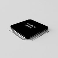
Controller TQFP44
...44
3docean
chip controller cpu electronic gpu mcu micro controller package smd tqfp tqfp44
a micro controller in a tqfp44 package
3d_export
$15
control unit
...control unit
3dexport
control unit
3ddd
$1
Yacht control
...yacht control
3ddd
yacht control
3d_export
$5
controle pgdm
...controle pgdm
3dexport
carcaca controle pgdm
turbosquid
free
controler
... available on turbo squid, the world's leading provider of digital 3d models for visualization, films, television, and games.
3ddd
$1
Control
...
http://www.schmitz-leuchten.de/html-ru/einzelleuchten-lampentyp-details.php?lamptype_no=700&group;=917&id;=731
3d_ocean
$4
Controller TQFP100
...100
3docean
chip computer cpu electronic gpu mcu micro controller pin platine silicon wafer
a micro controller in tqfp100 package
3d_ocean
$4
Controller TQFP64
...qfp64
3docean
chip computer cpu gpu mcu micro controller package silicon tqfp tqfp64 wafer
a micro controller in a tqfp64 package
3d_ocean
$7

Remote controller
... control switcher tv remote
remote controller for tv, sound systems etc easy to edit textures photo real rendered with mental ray
Mount
3d_export
free

mounting bracket
...mounting plate is the portion of a hinge that attaches to the wood. mounting plates can be used indoors, cabinetry and furniture.
turbosquid
$2

MOUNTING
... available on turbo squid, the world's leading provider of digital 3d models for visualization, films, television, and games.
turbosquid
free

Mounts
... available on turbo squid, the world's leading provider of digital 3d models for visualization, films, television, and games.
turbosquid
free

Mount Fuji
...fuji
turbosquid
free 3d model mount fuji for download as obj on turbosquid: 3d models for games, architecture, videos. (1579977)
3d_export
$5

Headphone mount LR
...headphone mount lr
3dexport
headphone mount l+r
turbosquid
$39

Mount rainier
...quid
royalty free 3d model mount rainier for download as fbx on turbosquid: 3d models for games, architecture, videos. (1492586)
turbosquid
$5

pipe mounting
...quid
royalty free 3d model pipe mounting for download as obj on turbosquid: 3d models for games, architecture, videos. (1293744)
turbosquid
$3

Mounting Tires
...uid
royalty free 3d model mounting tires for download as fbx on turbosquid: 3d models for games, architecture, videos. (1708511)
3d_export
$5

Magnetic GoPro Mount
...pro mount
3dexport
cool magnetic mount for gopro. allows you to mount the camera on flat metal surfaces and get exclusive shots.
turbosquid
$5

Stone Mount
...ty free 3d model stone mount for download as ma, obj, and fbx on turbosquid: 3d models for games, architecture, videos. (1370306)