Cults
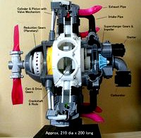
Radial Engine, 7-Cylinders, Cutaway
by Cults
Last crawled date: 6 years, 1 month ago
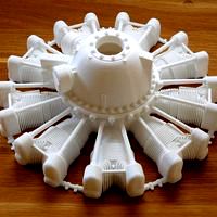
This is a model of the Radial Engine with 7-cylinder for old aircraft.
But, this type of engine includes many fundamental mechanisms.
This would be the optimal teaching material for the beginners' class engineers and students.
A. Features of this model are;
1. Cutaway model of entire engine;
①. Reduction Gears (Planetary)
②. Cam and Drive gears
③. Crankshaft and Rod assembly
④. Cylinder and Piston with Valve mechanism
⑤. Supercharger gears and Impeller
2. Air Intake and Exhaust Pipes
3. Simplified Accessories (Propeller Hub with half blades, Carburetor, Magneto and Starter etc.)
4. It can be rotational but not smoothly because of the valve mechanism resistance and friction.
Refer to: https://youtu.be/uaWTmbg4mlE
B. Print and parts information
There are approximately 80 stl parts and many hardware including the bearings.
Hardware can be purchased from DIY shop or WEB shop easily and can be changed to equivalent similar parts.
All parts data are included in the manual. Refer Numerical Index.
It takes very long hours to print parts, treatment after printing and assembling.
STL file name: "ws" of last 2 digits means "With Support" which special designed.
But some parts need additional slicer's support to these. Refer “Remarks” column.
Estimated net print hour will be more than 90 hours.
C. Assembly manual (.pdf format in Zip)
The detail assembly manual including "Parts-List", "After printing treatment" and "Assembly procedure" are prepared.
But there are many complicated parts which required finishing and machining (Filing, Drilling and Tapping).
Also there are many fits required adjustment of clearance and tightening using with many hardware.
Some sample manual pages are shown in photos.
This manual can be very helpful for disassembly and re-assembly just like overhaul.
D. General Notes
1. For M1.4 Screw: No need "Tapping". Drill with φ1.0 drill then direct screw-in.
2. Screw to AL pipe: Put in a screw into the pipe end, squeeze pipe by the plier. Check the fixed condition.
3. Small diameter shaft parts:
To keep the strength, Use "100% infill" at printing and apply the adhesive for acrylic resin.
4. Recommended Drills and Taps
Drill: 1.0, 1.5, 2.0, 2.5, 3.0, 3.2, 5.0, 5.2, 7.2
Tap: M2, M3
3D printing settings
Raft, Support, Layer Height, Infill: Depending on your experience.
But the parts having gear, small shaft and thin portion: 100% infill is recommended.
My models were printed by "idbox" using with 0.4 nozzle, 1.75 PLA.
Before "Down-Loading", please watch photos carefully and consider deeply.
I do hope your success!!
[Updated 2017.10.10]
YouTube Video changed to longer version.
[Updated 2017.10.16]
A typo was corrected on photo.
[Updated 2018.2.10]
"Assembly Manual" typo and hardware qty, etc. corrected.
"Revision Record" page is added as Page 28.
Similar models
cults
$16

Turboprop Engine, for Business Aircraft, Free Turbine Type, Cutaway
...m in the creations which i made before.
i do hope your success!!
[update] - 2018.3.14
photo of typical special support is added.
cults
$21

Propfan Engine, Pusher Type
...yer height, 40% infill and no raft and support)
note: when at actual print, each parameter may be adjusted by your experience.
cults
$10

Turboprop Engine, for Business Aircraft, Cutaway
... hope your success!!
[update 2017.12.15]
for "dummy propeller assy", related stl files (4), photo and image are added.
cults
free

Main Gear Box, Helicopter driven by 2-Engines
...15,2017)
new file (body-mid901.stl) and related photos are added to return "tail take-off output" at the same position.
cults
$1

Manual winch
...the set can be used to mount toys on the scale 0.5
gear ratio 0.5
the spring / lever assembly preparation see photo attached.
cults
$5

Jet Engine, Single-Spool with AfterBurner
...
price discount
[update 2017.12.14]
for "non-shrouded turbine blades rotor", stl file (3), photo and image are added.
cults
$5

Turbofan Engine, for Business Aircraft, Cutaway
...out 10 hours to print.
note: when at actual print, each parameter may be adjusted by your experience.
i do hope your success!!
cults
free

Turboprop Engine Modified Parts (No.3)
...ecommended.
still this is not the model to print and assemble easily, i hope your perseverance too.
thank you for your interest.
cults
free

Rotational Stand for Turboprop Engine Cutaway
...to.
- wood screws: appropriate screws can be used.
assembly points
- stl parts position will be adjusted by the model you made.
cults
free

Jet Engine, 2-Spool, Current
... layer height, 40% infill and no raft and support)
note: when at actual print, each parameter may be adjusted by your experience.

Cutaway
cults
free
Rotational Stand for Turboprop Engine Cutaway
...to.
- wood screws: appropriate screws can be used.
assembly points
- stl parts position will be adjusted by the model you made.
cults
$5
Turbofan Engine, for Business Aircraft, Cutaway
...out 10 hours to print.
note: when at actual print, each parameter may be adjusted by your experience.
i do hope your success!!
cults
$10
Turboprop Engine, for Business Aircraft, Cutaway
... hope your success!!
[update 2017.12.15]
for "dummy propeller assy", related stl files (4), photo and image are added.
cults
$16
Turboprop Engine, for Business Aircraft, Free Turbine Type, Cutaway
...m in the creations which i made before.
i do hope your success!!
[update] - 2018.3.14
photo of typical special support is added.
cults
free

Quadcopter 915F
...futuristic. stealthy. a lamborghini in a world of jeeps. cutaway chevrons, sleek propellers and elegant proportions lift this high-concept...
cults
free

Turboprop Engine Modified Parts (No.2)
...engine modified parts (no.2) cults engine jet engine turboprop cutaway mid class passenger airp ane i am a designer...
cults
$21
Propfan Engine, Pusher Type
...by a home type vacuum cleaner. 2. engine (gas-generator) cutaway model is inside of cowling, but it is not...
Radial
cults
free

Radial Door Bolt
...radial door bolt for exteriors or interiors.
feel free to customize it here: https://www.vectary.com/u/meshtush/radial-door-bolt
cults
free

Radial low-RPM Halbach array PM Generator with serpentine coils.
...radial low-rpm halbach array pm generator with serpentine coils.
radial low-rpm halbach array pm generator with serpentine coils.
cults
$10

DUMMY RADIAL ENGINE
...100 mm from hobby king, but can be printed to any model plane that have cowling diameter about 95 - 110 mm , also can be scalled.
cults
$22
Dummy radial engine. Pratt & Whitney R2800
... - 57 mm inside the joiner ring.
the model can be scaled up or down to fit your model.
for personal use only, not for resale.
cults
free

Radial drinks coasters with holder
...inting in multiple colours. for ours we printed them in our bubblegum pink, cool breeze blue and arctic white.
happy printing x
cults
$6

T28 Trojan dummy radial engine
...iameter about 95 - 110 mm , also can be scalled.
diameter - 96.oo mm
high - 16.oo mm
hole diameter for electric motor - 37.oo mm
cults
$13

Le Rhone spinning radial dummy engine for RC planes
...or low rpm motors spinning big, scale props. high rpm use can be dangerous. how you use the printed model is your responsibility.
cults
free
Wanhao Duplicator i3 Fan Duct
...to a 12v dc 50mm blow radial cooling fan. https://www.amazon.com/connector-cooling-blower-50mmx15mm-uxcell/dp/b00mju6jr2/ref=sr_1_fkmr0_1?s=pc&ie=utf8&qid=1476920027&sr=1-1-fkmr0&keywords=2v+dc+50mm+blow+radialcooling+fan the fan duct is to be mounted around the...
cults
free

Square Extrusion Clamp
...90 degree angle. it is meant for axial and radial loads, it will probably not do a good job...
Piston
cults
free
Toy Piston
...toy piston
cults
toy piston
toy piston
cults
$5
Piston Trophy
... car fun toy rock roll
piston style toy trophy
download contains both capped and cup style piston top, base and faux bolts.
cults
free

PISTON KEY RING
...piston key ring
cults
porteclef piston clef key keychain keyring ring
porte clef piston
cults
free

Detroit Pistons - Logo
...troit pistons - logo
cults
detroit pistons - logo
support your favorite sport team with this 3d printable 3d model!
cheers csd
cults
free

Hand spinner Two pistons
...hand spinner two pistons
cults
fdm_center spinner hand_spinner
hand spinner two pistons
cults
free

piston toy
...piston toy
cults
watch video! https://www.youtube.com/watch?v=oihurkj56mg
2016.10.23-fixed(more lite)
cults
free

New Hand spinner Two pistons
...new hand spinner two pistons
cults
fdm_center spinner hand_spinner
new hand spinner two pistons
cults
$3

Piston Cup - Duplo - Cars
...nted in the form of lego duplo, but may be suitable for other uses, leave the choice to your ideas ...
dimensions 41x35,5x37
cults
$1

Piston and connecting rod
...n adaptant le taille de ce piston et de cette bielle, cela peut devenir un objet de déco ou un nouveau porte clé pour la voiture.
cults
free

Stihl Piston Keychain
...tor of this is gary brinsden (brinny).
http://www.thingiverse.com/thing:7893
i made some changes and turned it into a keychain.
Cylinder
cults
free
Cylinder
...cylinder
cults
cylinder education school school.
educational material. cylinder.
x: 3 cm
y: 3 cm
z: 5 cm
cults
free

Cylinder Shape
...cylinder shape
cults
cylinder shape
cylinder shape
cults
free

3D Cylinder
...3d cylinder
cults
3d cylinder
3d cylinder
cults
free

Ring - Bevelled Cylinder
...ring - bevelled cylinder
cults
ring - bevelled cylinder
ring - bevelled cylinder
cults
free

Ambiguous Cylinder Illusion
...ambiguous cylinder illusion
cults
ambiguous cylinder illusion
ambiguous cylinder illusion
cults
free

Simple Cylinder Test
...simple cylinder test
cults
simple cylinder test
simple cylinder test
cults
free

European tool cylinder / European cylinder tool
...e needle screw
thickness of layer 0.3
shell thickness 0.6
fill rate 25
print temperature 220c °
support type everywhere
cults
free

Ring - Bevelled cylinder - holes
...ring - bevelled cylinder - holes
cults
ring - bevelled cylinder holes
ring - bevelled cylinder - holes
cults
$2

rotary cylinder furniture
...
8 drawer
1 structure
1 foot with axis of rotation
1 cover that sticks on the axis of rotation of the foot
#dagocults
cults
free

Telescopic Cylinder, Math, Geometry
...iece. the result, however, is aesthetically motivating.
have fun!
reference:
https://en.wikipedia.org/wiki/telescopic_cylinder
Cylinders
cults
free
Cylinder
...cylinder
cults
cylinder education school school.
educational material. cylinder.
x: 3 cm
y: 3 cm
z: 5 cm
cults
free
Cylinder Shape
...cylinder shape
cults
cylinder shape
cylinder shape
cults
free
3D Cylinder
...3d cylinder
cults
3d cylinder
3d cylinder
cults
free
Ring - Bevelled Cylinder
...ring - bevelled cylinder
cults
ring - bevelled cylinder
ring - bevelled cylinder
cults
free
Ambiguous Cylinder Illusion
...ambiguous cylinder illusion
cults
ambiguous cylinder illusion
ambiguous cylinder illusion
cults
free
Simple Cylinder Test
...simple cylinder test
cults
simple cylinder test
simple cylinder test
cults
free
European tool cylinder / European cylinder tool
...e needle screw
thickness of layer 0.3
shell thickness 0.6
fill rate 25
print temperature 220c °
support type everywhere
cults
free
Ring - Bevelled cylinder - holes
...ring - bevelled cylinder - holes
cults
ring - bevelled cylinder holes
ring - bevelled cylinder - holes
cults
$2
rotary cylinder furniture
...
8 drawer
1 structure
1 foot with axis of rotation
1 cover that sticks on the axis of rotation of the foot
#dagocults
cults
free
Telescopic Cylinder, Math, Geometry
...iece. the result, however, is aesthetically motivating.
have fun!
reference:
https://en.wikipedia.org/wiki/telescopic_cylinder
Engine
cults
free

Metronome Engine
...metronome engine
cults
metronome engine
metronome engine
cults
free

Engine block
...engine block
cults
engine car motor
monoblock
cults
free
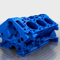
V6 engine block
...v6 engine block
cults
engine v6
cylinder block engine v6
cults
free

Xaar: Zyntari Engineer
...xaar: zyntari engineer
cults
xaar: zyntari engineer
xaar: zyntari engineer
cults
free

Working Train Engine "Kevin's Engine"
...p;quot;
cults
working train engine "kevin's engine"
working train engine "kevin's engine"
cults
free

Train Engine
...train engine
cults
model railroad constructor part number 1 train engine
model railroad. constructor. part number 1
cults
free
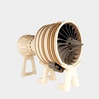
Jet Engine
...n assembling. remember: glue and patience go a long way!
all pieces print without support.
this model was designed by makerbot.
cults
free

Perendev engine
...perendev engine
cults
stl, solidworks, rar, ...
cults
free

RC model engine
...rc model engine
cults
this is a mockup of an enya rc model engine.
cults
free

STAR SERVO-ENGINE
...star servo-engine
cults
accessory
star for servo-engine with interior of 10 mm with thread and grip
7
cults
free

Bowl 7
...bowl 7
cults
bowl 7
bowl 7
cults
free

Poly Vase 7
...poly vase 7
cults
poly vase 7
poly vase 7
cults
free

Wire Box 7
...wire box 7
cults
wire box 7
wire box 7
cults
free

Hemisphere Bowl 7
...hemisphere bowl 7
cults
hemisphere bowl 7
hemisphere bowl 7
cults
free

String Vase 7
...string vase 7
cults
string vase 7
string vase 7
cults
free

Arrayed Vase 7
...arrayed vase 7
cults
arrayed vase 7
arrayed vase 7
cults
free

iPhone 7 Plus
...iphone 7 plus
cults
iphone 7 plus
iphone 7 plus
cults
free
7 segment display
...7 segment display
cults
7 segment display
7 segment display
cults
free

Trophy Riser 7
...trophy riser 7
cults
trophy riser 7
trophy riser 7
cults
free

Nexus 7 Bumper
...nexus 7 bumper
cults
nexus 7 bumper
nexus 7 bumper