Thingiverse
Quadbot 17 by m3atsauc3
by Thingiverse
Last crawled date: 3 years ago
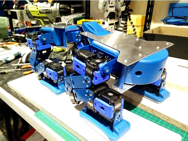
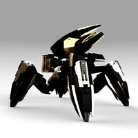
This is Quadbot 17, a work-in-progress quadruped robot born out of a learning exercise in Autodesk Fusion 360.
This quadruped robot will use AX-12A Dynamixel servos (might be upgraded to the more powerful AX-18A). The legs currently have 20 DoF and there are an additional 2 DoF for the body. Servos and brackets are from the Robotis range, with some replaced by their metal counterparts available from Trossen Robotics. They will be painted to match the colour theme. The rest of the robot is designed with 3D printed parts in mind. The main framework of printed parts forming the body will be sandwiched between 1.5 mm thick custom plates.
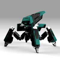
The novel aspects of this quadruped are its articulated legs, which have higher DOF than usually found on small quadrupeds, and its articulated "spine", which will help it in navigating uneven terrain.
A number of options are considered for the "head", or main sensor pack: an XBOX Kinect v2 time-of-flight sensor, a Scanse Sweep LiDAR and an Intel RealSense depth-sensing camera.
Currently, a hardware test rig of one leg has been built, and the kinematics have been calculated and tested.
Update 18-12-2017
A temporary chassis has been built using MakerBeam aluminium profiles, so the next stage is to start building the CAD modelled chassis, out of aluminium sheets and 3D parts, then focusing on getting more effective walking gaits.
A walking gait has also been implemented: A Python test program reads the up/down and forward/back position of each leg for a number of frames that make up a walking gait, the IK is solved, and the resulting joint values are streamed via serial over to an Arbotix-M, which simply updates the servo goal positions.
Update 05-02-2018
The prototype custom chassis is complete!
All parts of the custom chassis have been printed in PLA plastic on a FlashForge Creator Pro. The structure is strengthened by pairs of aluminium plates. All plastic parts have been sanded and spray-painted.
I threaded the holes on all the 3D parts, which were either 3 mm wide where the aluminium plates attach, or 2 mm at the leg and spine bracket attachment points. Using a tap for the 3 mm holes worked pretty well, but the 2 mm holes were more prone to being stripped or too loose, so manually threading the holes with the bolts worked better.
This quadruped robot will use AX-12A Dynamixel servos (might be upgraded to the more powerful AX-18A). The legs currently have 20 DoF and there are an additional 2 DoF for the body. Servos and brackets are from the Robotis range, with some replaced by their metal counterparts available from Trossen Robotics. They will be painted to match the colour theme. The rest of the robot is designed with 3D printed parts in mind. The main framework of printed parts forming the body will be sandwiched between 1.5 mm thick custom plates.
The novel aspects of this quadruped are its articulated legs, which have higher DOF than usually found on small quadrupeds, and its articulated "spine", which will help it in navigating uneven terrain.
A number of options are considered for the "head", or main sensor pack: an XBOX Kinect v2 time-of-flight sensor, a Scanse Sweep LiDAR and an Intel RealSense depth-sensing camera.
Currently, a hardware test rig of one leg has been built, and the kinematics have been calculated and tested.
Update 18-12-2017
A temporary chassis has been built using MakerBeam aluminium profiles, so the next stage is to start building the CAD modelled chassis, out of aluminium sheets and 3D parts, then focusing on getting more effective walking gaits.
A walking gait has also been implemented: A Python test program reads the up/down and forward/back position of each leg for a number of frames that make up a walking gait, the IK is solved, and the resulting joint values are streamed via serial over to an Arbotix-M, which simply updates the servo goal positions.
Update 05-02-2018
The prototype custom chassis is complete!
All parts of the custom chassis have been printed in PLA plastic on a FlashForge Creator Pro. The structure is strengthened by pairs of aluminium plates. All plastic parts have been sanded and spray-painted.
I threaded the holes on all the 3D parts, which were either 3 mm wide where the aluminium plates attach, or 2 mm at the leg and spine bracket attachment points. Using a tap for the 3 mm holes worked pretty well, but the 2 mm holes were more prone to being stripped or too loose, so manually threading the holes with the bolts worked better.
Similar models
thingiverse
free

Quadruped Leg (V4) by Cybeaer
...)
so this is a try to make more stable and light legs for my quadruped.
and for tests with the gait walk animation programming ;)
grabcad
free

4 LEGGED ROBOT, QUADRUPED WITH RASPBERRY PI, MIT ROBOT ,
...raspberry pi, mit robot ,
grabcad
4 legged robot with raspberry pi and 12 \servo motor , with cameras and sensor , 3d printing ,
thingiverse
free

Educational robot quadruped by kwendenarmo
...
designed to be controlled from scratch by arduino, all sources: https://github.com/tallerinventores/educational-robot-quadruped
grabcad
free

Design of Quadruped robot using Theo-Jansen Mechanism
...bionic replica of spider (arachnid species) that uses their legs for movement and can perform tasks either by human interaction .
grabcad
free

Legs in series for a robot
...iminary legs for our quadruped robot. they are serial in nature and have 2 servo lx 16a motors. they will be 3d printed with pla.
grabcad
free

6 DOF Robot Arm Based on Popular Servo Bracket Chassis
... arm based on popular servo bracket chassis
grabcad
six degree of freedom robot arms with chassis made of popular servo bracket.
thingiverse
free

AT-AS quadruped (or hexapod) robot by Anandromeda
...modules. but this robot accepts others microcontrollers, servos (with similar dimensions) and others components for its control. use the...
grabcad
free

8 DOF quadruped test bed for Robotics
...8 dof quadruped test bed for robotics
grabcad
rudimentary design of the robot. easy to simulate and makable in real life.
grabcad
free

Quadruped Robot Dog
...quadruped robot dog
grabcad
simple robot dog with 4 legs and 8 servo motors.
grabcad
free

Quadruped Robot
...ed robot with 3 dof in each leg. it is designed so simple so that the manufacturing can be done in laser cutting. and 3d printing
M3Atsauc3
thingiverse
free

Perry the Platypus Keychain by m3atsauc3
...ize and four scaled versions made: 80%, 70%, 60%, 50%. choose the one that suits you!
images shows a 3d print of the 70% version.
thingiverse
free
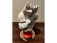
Heart Thirds with Tabs and Stand by m3atsauc3
...isassembly without glue.
also created a customised stand, printed here in flexible plastic; add some blu tack to keep it secured!
thingiverse
free

Chip-E-lata by m3atsauc3
...hallenge aims to find out! will it work? who knows!
features:
walking
two-wheeled rolling
laser scanner
water firing
water turret
thingiverse
free

Custom Backpack for Bioloid robot by m3atsauc3
...or slotting in large batteries (~2200 mah) as they are too big to fit within the backpack, and another version without the holes.
Quadbot
turbosquid
$59
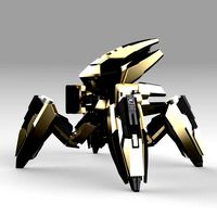
Quadbot 212F
...osquid
royalty free 3d model quadbot 212f for download as ma on turbosquid: 3d models for games, architecture, videos. (1523301)
turbosquid
$59

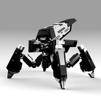
Quadbot 202F
...osquid
royalty free 3d model quadbot 202f for download as ma on turbosquid: 3d models for games, architecture, videos. (1521042)
turbosquid
$59
Quadbot 102F
...osquid
royalty free 3d model quadbot 102f for download as ma on turbosquid: 3d models for games, architecture, videos. (1521023)
turbosquid
$39
Quadbot 211F
...osquid
royalty free 3d model quadbot 211f for download as ma on turbosquid: 3d models for games, architecture, videos. (1523300)
turbosquid
$39

Quadbot 201F
...osquid
royalty free 3d model quadbot 201f for download as ma on turbosquid: 3d models for games, architecture, videos. (1521037)
turbosquid
$39

Quadbot 111F
...osquid
royalty free 3d model quadbot 111f for download as ma on turbosquid: 3d models for games, architecture, videos. (1523286)
turbosquid
$39
Quadbot 101F
...osquid
royalty free 3d model quadbot 101f for download as ma on turbosquid: 3d models for games, architecture, videos. (1521019)
3d_export
$79

Quadbot 201f
...bot_201f.mb 2018<br>quadbot_201f.mb 2017<br>quadbot_201f.mb 2016<br>quadbot_201f.obj<br>quadbot_201ff.fbx
3d_export
$99
Quadbot 202f
...bot_202f.mb 2018<br>quadbot_202f.mb 2017<br>quadbot_202f.mb 2016<br>quadbot_202f.obj<br>quadbot_202ff.fbx
3d_export
$79
Quadbot 211f
...dbot_211f.ma 2017<br>quadbot_211f.mb 2016<br>quadbot_211f.ma 2016<br>quadbot_211f.obj<br>quadbot_211f.fbx
17
3d_export
$6
rocks 17
...rocks 17
3dexport
rocks 3d model 17
3ddd
$1
PLANTS 17
...plants 17
3ddd
цветок , горшок
plants 17,, pots in diameter 100,80,60,40cm,,, enjoy
3d_export
$6
tap-17
...tap-17
3dexport
3d_export
$6
set-17
...set-17
3dexport
3d_export
$27
C-17 Globemaster
...c-17 globemaster
3dexport
c-17 globemaster
3ddd
free
Renault FT-17
...renault ft-17
3ddd
ft-17 , renault , танк
turbosquid
$40
cottage 17
...bosquid
royalty free 3d model cottage 17 for download as max on turbosquid: 3d models for games, architecture, videos. (1377003)
turbosquid
$30

Apartment 17
...squid
royalty free 3d model apartment 17 for download as max on turbosquid: 3d models for games, architecture, videos. (1432680)
turbosquid
$10

Surfboard 17
...squid
royalty free 3d model surfboard 17 for download as max on turbosquid: 3d models for games, architecture, videos. (1375686)
turbosquid
$7
Rock 17
...turbosquid
royalty free 3d model rock 17 for download as obj on turbosquid: 3d models for games, architecture, videos. (1486522)